Hi, I am using MTH Realtrax on my railroad layout and a short while back I added a lead track to my small rail yard.  The yard has a series of switches at each end creating ladders that connect to the lead track which then connects to the mainline.  In order to do that a left hand switch was needed at one end to join the ladder to the lead track.  I installed the switch, but in order to do that I had to remove a small bit of plastic off the roadbed base of the left hand switch.  This allowed the left hand arm of the left hand switch to butt up to a right hand ladder switch.  No big deal, but my having to do that made me think that MTH had not designed the switch for this particular application.  With that said, I put the switch in place and wired it up so it could be activated by push button switch along the side of the layout.  Everything seemed to work fine.  No apparent problems until on evening I was running trains, smelled a foul odor and discovered that the switch I had just intalled had "fried". I had been running trains for pehaps 30+ minutes.  When I took the back of the switch off I found that the red wire connected to a very thin metal strip that runs underneath a white plastic throw bar like mechanism and the strip itself had overheated and melted.  I don't know what happened.  What caused the red wire and metal strip to overheat to the point that some of the parts began to melt is a big question that I hope somebody can help me with.  I am also asking for help to figure out how I can solve this problem as the left hand switch at this location is pretty critical to my making the lead track work.  Below is a picture of another left hand switch so that you can see how the switch is wired.  Any ideas/help would be very much appreciated.  Thanks, Bo 


MTH O-72 Left Hand Switch 004


Visit my website Bo's Trains at http://www.bostrains.com


Attachments

Images (1)
  • MTH O-72 Left Hand Switch 004
Last edited by railhead53
Original Post

Replies sorted oldest to newest

I can really use some help as I'm stumped as to what caused the left hand switch to fry.  I thought I would provide a couple more photos.  The first picture shows a close-up of the damage that was done and the second photo shows the application I was trying to use.  The switch has been removed, but you can see where it was installed to connect the yard ladder to the lead track.  I am hoping that some of you guys with electrical/electronics expertise can offer some ideas of what caused the damage and how I can resolve the issue.  I have a replacement left hand switch available for use, but don't want to try to use it until I have a possible solution to the problem.  Thank you, Bo   


Left Hand Switch Issue 1-7-13 016


Left Hand Switch Issue 1-7-13 003

Attachments

Images (2)
  • Left Hand Switch Issue 1-7-13 016
  • Left Hand Switch Issue 1-7-13 003

Greg, thanks for your thoughts and insight to what possibly happened and a possible fix.  I am still wondering if my particular application had anything to do with the switch burning out.  If you look at the photo showing how the track is layed out and try to do that with some similar track pieces you will find they will not go together without some minor modification.  I'm wondering if there is something in the circuitry that is heating up because of the way I am using the left hand switch?  Thanks again for your help.  Bo 


Visit my website Bo's Trains at http://www.bostrains.com

Bo, I have put them in almost every configuration imaginable. Curve to curve, curve to straight (either end of the straight) and mated O31 to O72 and O42.... there should be nothing that you did to cause the problem.  Keep in mind, I say that without seeing your actual plan.


Sometimes, things just go bad. Greg

I'm very interested in this subject because I've been having issues with two switches that i have inline. I usually need to unplug the auxiliary power and then turn it on again. Then it will work a random number of times before it starts acting up again. The symptoms are when the switch is thrown the track will not switch completely, but return to its starting position. If I then attempt to throw the switch again the switch will freeze and appear to short I.e all lights go out on the switch and it will stop functioning until I reset the power again.  I've tried replacing the remote switch and motors as well as the position but nothing seemed to have an effect.


~MattS

Originally Posted by railhead53:

Greg, thanks for your thoughts and insight to what possibly happened and a possible fix.  I am still wondering if my particular application had anything to do with the switch burning out.  If you look at the photo showing how the track is layed out and try to do that with some similar track pieces you will find they will not go together without some minor modification.  I'm wondering if there is something in the circuitry that is heating up because of the way I am using the left hand switch?  Thanks again for your help.  Bo 


Visit my website Bo's Trains at http://www.bostrains.com

Your application should be fine. O72 1/2 curves come scored, so you can take the piece you mention off track. I have to take that piece off, so my Wyes can go parallel. Given how much fun these are, I will be researching the different switch brands, before I go from Christmas only to year round.

Thanks guys for your input.  I believe your right that there is no reason why the left hand switch should not work in the application described above.  I'm going to install the replacement switch and see how it goes.  I'll work with the damaged switch as well to see if I can bring it back to life.  If a similar problem occurs with the replacement switch, I'll come back and let you all know.  Thanks again,  Bo 


Visit my website Bo's Trains at http://www.bostrains.com

I know it is better to remain thought a fool than to speak up and remove all doubt.  So, my comment and question that follows is to add a little to my education.  It appears from your description of your junction that the right turnout following the left, that there would be no ground on either outside rail of the right hand curve due to the lack of connections on the inside rails of that combination.  If that be the case, then somewhere along the line you must have another ground leading to your lockon for that track.  Maybe you added one, and in doing so created a + to + that shorted and burned at the weakest connection point.  Or maybe the automatic anti-derailing feature somehow made that connection.

I have trouble with power failures around MTH switches all the time, but usually get them to work, but don't know why.  Just trial and error.  Someday I'll blow something up!

Bob, I appreciate your thoughts on the matter.  I am not sure just what the issue is.  I have discovered that standing alone, the switch seems to do fine, but when I hook up the three wire connection for the controller, just like I always do with my switches, it begins to heat up.  When I unhook the wires for the controller the problem of over heating seems to go away.  When I hook up the controller, it seems I am creating the problem.  I'm just not sure what the problem is and therefore do not know what the fix might be.  Any ideas?  Bo


Visit my website Bo's Trains at http://www.bostrains.com


I did not go back and read the original post, but if what you wrote last is true, it points to a controller.


If you have another controller, test the switch with that one.


If you do not, just hook up three wires and power the switch. Touch wire on the outside terminal to the other outside terminal....the switch should throw unless it is in the opposite postion. Change it from curve to straight (or vice versa) and test again. A wire from the center to an outside post (It has tobe the gnd one...and I am not by a switch right now) should throw the other way.


The motor has to be on for it to work. Try the same test with the motor on the other side...and make certain that the switch and the motor each have the respective magnets, and that they each attract to each other when you install the motor.


Does not work that way? You may indeed have fried something. That is the only advice I can give you, perhaps a wiser than me person can help you.


I do know I got one working one time by taking out the capacitor at the other end. I was told it was "really needed, or they would not put it there." Well, it still works years later. The blind pig as the old saying goes, I guess.


Sorry, best I can do. Greg

Since it is always possible for a solenoid to short out I have added 10 watt limiting resistors in series with each of my MTH turnouts. I use AUX power (not track power) to feed each solenoid. In addition I use a 4 ampere fuse as a backup protection for each pair of turnouts.  My turnouts are arranged as crossover tracks and are operated in pairs via a signal from an MTH AIU.


Note: Each MTH turnout operates at 10 volts and 1.25 amps. The "in series" resistance limits the short circuit current to 1.75 amps for each turnout solenoid.


This circuit protection ensures that any single failure does NOT affect the track power nor any other turnouts or accessories.

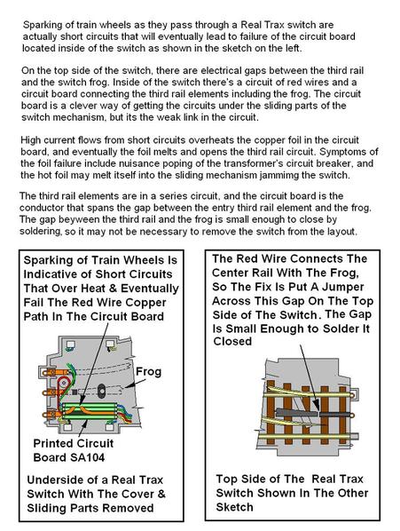
I have posted this elsewhere in the past. Here it is again, to indicate the solution that  was posted above and how to do it.


Not very elegant, but is works...until it gives up. Then, you hit it with the Weller 140 watt gun tip until the next time!


Many of my Realtrax switches (used seasonally) are hitting 14 to 15 years old, and most have some type of repair/jerry-rig to them. Greg


RTX sw repair

Attachments

Images (1)
  • RTX sw repair

Actually, the fix offered while functional, is not addressing the cause.

The cause is poorly gauged wheels shorting the Frog to an outside rail.

This causes LOTS of current to flow in that small conductor, creating an overheat condition.

I am using a cheap and dirty fix.

Cut a 1/4" wide strip of duct tape and place on the side of the frog.

Look for the scorch marks, that will tell you where it is shorting.

Since I added the strips of tape, no more meltdowns in the switches, no more popped breakers, ect.

A better fix involves more guard rails (or shimming them) and re-gauging wheels.

Since that is a lot of work, I'll stick with my tape.

Russell,


 agree that one of the principal causes of switch failure is the shorting of wheels on the center rail in Rail King switches. Instead of using tape, I paint the sides of the center rail segments with black epoxy paint using the spark etch marks as a guide. Specifically, I use POR 15 Chassis Black which I also use on my car restoration projects. No primer is necessary for POR 15 as it adheres well to clean bare metal. 


However, the copper path in the PCB is inadequate to handle the current draw of 7 & 8-car passenger trains.


In the aggregate, Rail King switches are in need of a few design enhancements to assure top notch performance.

Bobby, That is why most folks say to have power drops on all 3 tracks leading to a switch.

Then you are only powering the engine for a brief period as it passes over and it may be pulling from another spot as well, depending on pickup spacing.

A lighted car should always be pulling from one end on actual track, not the switch.

None of my lighted cars have only one pickup but I don't have very many of them.


Short Circuit Protection for turnouts:


As a suggestion to avoid "meltdowns" from any kind of short circuit I have designed my MTH turnout controls so that the current is always limited to 1.75 amperes per solenoid and 4 amperes total for all pairs of turnouts (which are operated simultaneously). I use separately fused External Power (not track power) for all turnout controls.


My crossovers are all operated in pairs and are controlled by separate 40 ampere relays. These relay circuits have 10 watt series resistors which limit the continuous short circuit current for each trunout solenoid.


These relays are in then separately operated by my MTH AIU. This means that no turnout circuit power is ever directly controlled by the internal AIU relays since the AIU circuits are isolated by the relays.


I also have circuit breaker and fuse protecton for all power circuits including TIU track power.


Post

OGR Publishing, Inc., 1310 Eastside Centre Ct, Suite 6, Mountain Home, AR 72653
800-980-OGRR (6477)
www.ogaugerr.com

×
×
×
×
Link copied to your clipboard.
×
×