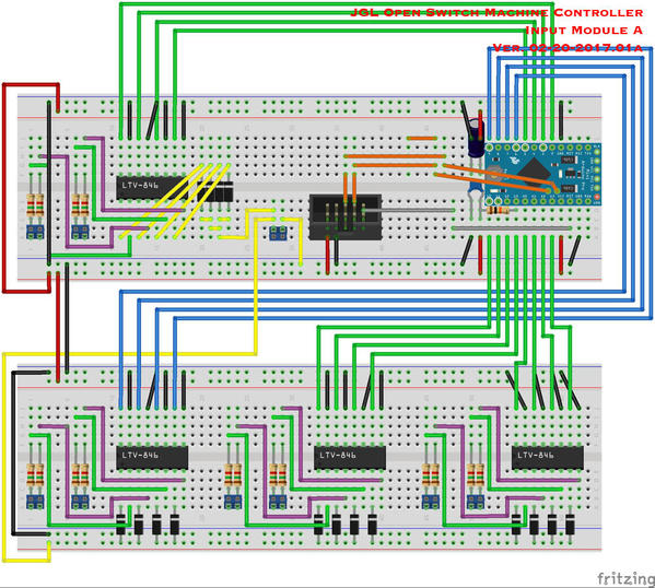
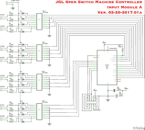
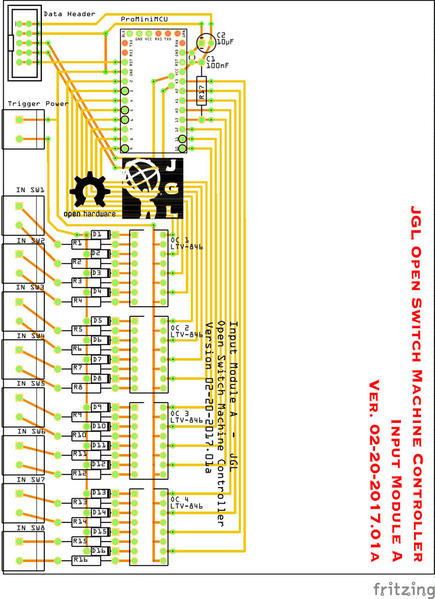
Puttzing around a bit more, and I think I have a working Input Module that should be fairly simple for most folks to put together now. I'm still working on the output end of things.
The plan is to use a single $2 ProMini clone to replace the pair of shift registers as well as the Schmitt triggers. We can also eliminate all but one of the pull-up resistors as the microprocessor has built in pull-ups that can be activated in software. Just to be safe I'm still using a pull up on pin 13, because the onboard LED can make that pin's internal pull-up act flaky. The ProMini here will communicate with the main micro-controller over the I2C bus, which allows for high speed, two way, communication between many devices (over relatively short distances).The code running on the ProMini here will be pretty simple. It will poll the inputs to check if they are active or not and store the results, then when it is asked for the data over the I2C bus it will report the current state of each input.
The down side of this set-up is that each module will have to have a unique address programed in when it is set up, because every last I/O pin on the thing is being used already, leaving no option for a hardware addressing solution. I'm thinking I can incorporate some sort of fairly easy to use 'programing module' into the system to make things easier. Additionally if multiple sets of switch controllers are not being linked together, the default address for each module should work with no problem as they will not be talking to other units with the same address.
Once again, the PCB layout is optimized for perforated project board, however the layout should work in a proper two-layer PCB as well.
My testing concurs with the data sheets of the parts in use, and this set up will work with AC track voltage input consistent with normal conventional control of 8VAC to 20VAC, or it will work using a separate accessory transformer for the inputs. My preferred method is still to use a DC power supply with ground connected to the track common, and I'd recommend using 12VDC on the 'trigger power' input.
I don't suggest anyone build any of this quite yet, just in case something doesn't work out for some reason. I do plan on putting together a fully working model before I suggest anyone else jump in.
JGL


