
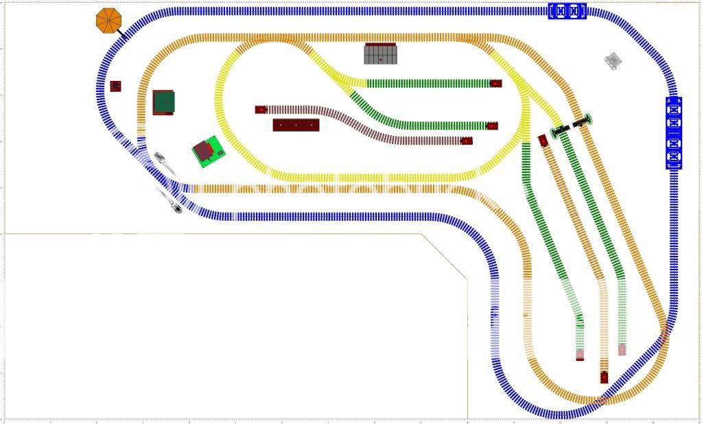
I know this has been talked about many many times but it's no longer on the forum that I can find. Does anyone have an updated version of the 1957 Lionel catalog Super O layout? Since I'm tearing my layout apart and doing it over, I was thinking long and hard about it and decided that layout was what I really wanted anyhow.

I don't want to do it in Super O as I don't have any and it's hard to find but I was thinking that since it's two 5x9 boards I can do it with O-27 profile track with my Marx 34" and my Lionel 42" curves.

If anyone could help I'd be grateful.

Edit: Added a picture in case I wasn't clear which layout I was talking about.

Attachments

Images (1)
  • 001
Last edited {1}
Original Post

Replies sorted oldest to newest

Solar,

I seem to remember a CTT article about building this layout and correcting the flaws obvious in the photo. Might be worth a search of old CTTs.


According to a web search, info about creating this layout is also found in the following books:

All Star Electric Trains of the 1950s by Roger Carp (Kalmbach)

Classic Lionel Display Layouts also by Roger Carp

Model Railroading - A Family Guide by Bruce Greenberg

All out of print but might be available from various sellers on Amazon.


There is also a TCA "e" article found here:

1957 layout

No info on creating it, but interesting commentary on one of the most famous catalog sketches of all time. Was there any kid (or dad!) that wouldn't have wanted this great layout after seeing that sketch? Smile

Jim
After some studying up on all the information I got in the last few days, I've come to a few conclusions. First, this layout is actually really huge. Second, it wouldn't be easy to do and keep it in the 9x14 space while using different radius curves.

Fortunately for me, I have Marx 034 wide radius curves at my disposal. This works with 027 track and I have enough to do the layout. I think I can even cut it down by about 18 inches and still be good.

Here is my mockup. This uses the Marx 034 curves, Lionel 027 straight track and half curves, Lionel 027 turnouts and the odd custom cut about 3 spots.

The next big challenge for me is going to be the benchwork. My previous attempts at benchwork were really terrible. I've used 2x4's before because I am a bigger guy at 250 lbs. and the benchwork and table top needed to support my weight. This layout will also have to support my weight at times.

This layout is going in a corner and I'll have limited to no access to the back sides. One thought I had was to build the benchwork out of 1x4's. They're light but will they support my weight? Then what to fasten them with?
Last edited by SolarEclipse2
quote:
Originally posted by SolarEclipse2:
I had a friend of mine who is an engineer help me with the table design. This is what we came up with, it uses 1x4's and cabinets from home depot.


That's a good way to support your layout and gain nice, organized storage in the process. Have you considered looking at a cabinet recycler for used kitchen cabinets? One of the other forum members was telling me he got enough cabinets for his entire layout for under $100.
Here's the second part. My friend broke it down into separate tables and included the cabinet placements. Both of the tables, as designed require only 15 1x4's.

Still having a hard time finding reasonably priced cabinets. I checked a second hand store, a re-store, and came up nothing. There are no real "cabinet recyclers" in the area that I can find.

Attachments

Files (1)

Hi SolarEclipse2,


Before you get too far along you might want to consider adding casters to your benchwork legs as I did. Makes it real easy to access all parts of the layout, plus you may want to paint scenery on the basement walls (etc.) at some point. Just a suggestion that worked well for me. Good luck with your classic layout!

Bill


Although 1957 was the year they introduced Super O, that layout, as drawn, does not use Super O.  Look closely, it uses tubular track, most likely O-31 due to the FM.

However, the 1960 Operating manual does have a detailed diagram (wiring and track count) of that layout and the track used in that diagram is identified as Super O. 


Bill


If at all possible I would move the tables about 12-14" our from the far [ windowless ] wall, eg towards the photographer so you have access on that far side -- where, naturally, most of the turnouts are.  You'll need that for access once built -- especially since you have backing moves through curves into those stubend sidings.


You might want to consider modifying the layout slightly so the two turnouts at the lower left are not shared by the two main routes;  instead, make it a pair of crossovers, and you can continuous run both loops without interlocking.


Incidently, to other potential builders:  Ping pong tables are 5 x 9, and it used to be possible to buy them as kits with quite substantial wooden underframes, interlocking with no hardware.   That was what I did when I built 'this' layout [ though without the back and forth tracks, + some other changes ] in '58 or so.


Best rgds, SZ

SZ, moving the tables out from the wall would be ideal however they "just" fit in this room. What I'm going to end up doing is moving the table on the windowed wall out of the way, build out that back table, then move the table back to the windowed wall. My basement isn't small but to move the layout away from the wall is to knock out a wall. My wife actually suggested that earlier.


Can you do a drawing of what you're talking about with the lower left hand corner switches? That sounds like a better idea than the interlock as it is now.

I did not make my suggestion clear enough:

   I realize the width of the room precludes moving both sides away from the walls.  But from your photos it appears there is no wall at the closest [ nearest the photographer ] end.  I'm suggesting the layout be moved in that direction 12" [ more or less, depending upon your waistline ] from the far wall -- the layout remains up against the window wall.  To access this you crawl or scoot under the layout, rather than up and over.

   Are you actually doing, from your table arrangement, a mirror image of the '57 layout ?

   No sketch capability.  Maybe some kindhearted soul, or even a 2 railer, can do that.


Best, SZ

Originally Posted by Steinzeit:

I did not make my suggestion clear enough:

   I realize the width of the room precludes moving both sides away from the walls.  But from your photos it appears there is no wall at the closest [ nearest the photographer ] end.  I'm suggesting the layout be moved in that direction 12" [ more or less, depending upon your waistline ] from the far wall -- the layout remains up against the window wall.  To access this you crawl or scoot under the layout, rather than up and over.

   Are you actually doing, from your table arrangement, a mirror image of the '57 layout ?

   No sketch capability.  Maybe some kindhearted soul, or even a 2 railer, can do that.


Best, SZ

Oh, there is actually the hot water heater and furnace and then I'm actually standing in the bathroom door. I've got about 8 inches between the end of that table and the hot water heater which is next to the furnace.

Originally Posted by SolarEclipse2:
Oh, there is actually the hot water heater and furnace and then I'm actually standing in the bathroom door. I've got about 8 inches between the end of that table and the hot water heater which is next to the furnace.

Ah, those pesky utilities.  OK, I understand.   Judging from the table layout, you are not really doing the catalog layout, since you have the tables in a mirror image.  How about moving just the right [ as viewed in photo ] table out from the wall a bit so you can get back there.  I think access, not so much for building but for troubleshooting, derailments, etc,  is a problem with your configuration myself [ speaking from experience in having built 'this' layout in an 11 x 14' room;  we allowed a 1 ft gap between the wall and the long side of the layout ].


In all honesty I would suggest another track plan that puts the majority of turnouts /  working accessories, and so forth within 3 ft of an accessible edge.  But I also think that if this trackplan is what you really want -- build it and have fun !


Best, SZ

Yes I'm building the mirror image of the layout. That's what my space allows. The track plan is really what i want feature wise. Even with a foot on each side, it wouldn't matter. I wouldn't fit. I have to do all of my troubleshooting before everything is final. I plan on laying it all out and testing as much as I can with the tables separated then joining the two sides.

Another point is that I plan to build from the back out. The tables are designed with the cabinets (in the future) to be sturdy enough to support me on top.

Again, eventually a wall will come down and I can move the table out or I can get one of those elevated creepers.

Since you built the layout already I'd love to see any pics you have of what you've done. Any other information would be great.
Originally Posted by CSXJOE:

I'm planning on duplicating the 1957 layout also after finishing the D190 display layout.  I posted a "Wanted" note at work for (2) regulation size ping pong tables to use as the benchwork. If not, I'll build the benchwork from scratch.

Ping pong tables would be good. Your local craigslist might have some ping pong tables as well. I built mine from scratch because i like the idea of having the cabinets underneath. I have a whole closed in the house with Lionel boxes in it, that space could be better used if I transfer it all under the layout.

Wow. I can't believe it's been over a year since I started this threat. I apologize for the lack of updates.Over the last year my wife and I had cared for my elderly and sickly grandfather who passed late August and we also had to put my father in a nursing home in July.


I haven't made any progress since building and sheeting the tables. Since my grandfather's bedroom was right above where the tables are, some of the ply has to come off due to spills coming through the floor and down on to the sheeting.


The plan is to sheet the tables again and then lay out the track.

Post
The Track Planning and Layout Design Forum is sponsored by

AN OGR FORUM CHARTER SPONSOR

OGR Publishing, Inc., 1310 Eastside Centre Ct, Suite 6, Mountain Home, AR 72653
800-980-OGRR (6477)
www.ogaugerr.com

×
×
×
×
Link copied to your clipboard.
×
×