I am breaking this off into a separate thread so that I do not clutter up the sensor thread with my basic electrical questions. 

While asking about running LED's from track voltage GRJ said

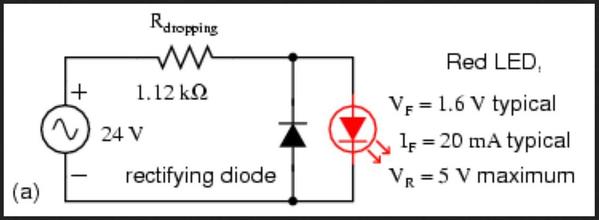
"it's almost as easy to run the LED's off the AC, you just add a diode to protect against reverse polarity, the current limiting resistor, and the LED."

When I asked "Just a diode and resistor, you do not use a rectifier?"

GRJ answered "A diode is a rectifier"

I understand this at a very basic level, but do not understand why one would choose one solution over another.
Is there a simple answer that would help me to decide in the future? 

Original Post

Replies sorted oldest to newest

Maybe I just used the wrong words.
I think A diode is this:
DIODE

And a RECTIFIER is this
RECTIFIER

I see that what I am calling a RECTIFIER is more properly called a RECTIFIER BRIDGE, maybe that is why it seems like I am asking the same thing twice?

The reason I am asking is I see that other LED powering options (for instance GRJ lighting board, or the little 5V one just done on this forum to be like the EVANS thing) have a rectifier bridge first, then a little power supply, then the resistor.   I think I under stand that the PS is making the power more controlled and all, but I thought it was the rectifier that made AC to DC.  I also understand the the rectifier bridge is a clever combination of diodes in a convenient package.

But when GRJ suggested just use a diode and resister to power the LED, I got to wondering why one would do it one way over another?

Is this now clearly two solutions?  Or have I still said the same thing twice?

You might be clinging to your assumption of the meanings of the words. Diode and rectifier are two words meaning the same thing. Diode = rectifier = diode = .... etc. The two words are used interchangeably and mean the same thing.

If you stop thinking that the two terms mean different things, the circuitry descriptions might make more sense to you.

Last edited by RoyBoy

Hmm, I am struggling a little to follow the inner working of the bridge rectifier, however it makes sense that it would yield a higher voltage.  I think of AC like water 2 sides going forward and back.  With a single diode you only get the the forward on one side, with one on each side you get the forward on both sides (sort of) 

But I still am wondering.
In almost all cases when we are using these things to run for instance 12V LED's we end up using a resistor to drop the voltage any way.  So why not use a single diode to get some voltage drop for free?

You are getting yourself all confused by mixing what you "think" with what "is."

1.  A single diode will slice off the top (or bottom) of a sine wave, resulting in a pulsating "half-wave" of alternating current. It will power a D-C device that can handle that type of wave-form. Using 4 diodes in a bridge results in all the electricity (tops and bottoms of the sine wave) being arranged at the output in a steady (slightly pulsating) Direct Current.  

(quote) "...we end up using a resistor to drop the voltage any way." (end quote)

2.  A resistor is not used to lower voltage. It is used to lower CURRENT (amperage), and over-current is what will blow out an LED. So, an LED requires a CURRENT limiting resistor, and a diode for protection from reverse polarity from an A-C source.

I'm sure there are YouTubes that describe, with diagrams and waveforms, how this all works.


Last edited by Arthur P. Bloom

Remember folks, this was for use with an LED.  Since the LED only uses one half of the cycle anyway, I simply put the diode in series to protect the LED against reverse polarity.  A standard LED only tolerates 5-6 volts reverse polarity, running them off AC will exceed this.  While the current limiting resistor will minimize the reverse current, the LED will last a lot longer if it's never sees the excess reverse voltage.  Rob shows the resistor wired reverse polarity across the LED.  While that works, it does double the power dissipation in the resistor, so I tend to put it in series.  It drops the resistor power to where I can use 1/4W parts instead of 1/2W power for 18V track voltage.

APA
(quote)'You are getting yourself all confused by mixing what you "think" with what "is."'
Agreed, this is often the case, what we think is what is true for us, the trick can be realizing our thought is wrong.

I am trying to see how what I am thinking is wrong, it is however difficult to get past the filter of my thinking to get to what is.
I feel as if I am missing some sort of basic understanding, which continues to allude me. (I am a mechanical engineer rather than an electrical so I never quite fully figured this)

I keep asking questions becasue I am hoping that something will click and I will get it.

I actually understand that a resistor changes current, I just keep thinking of it wrong for some reason.  I push the whole thing thru ohms law and thinking in terms of voltage.  I think my confusion lies somewhere in here, but have not yet got it.

Your item 1 explains a little, I was thinking of the diode as yielding pulses of DC rather than 1/2 AC.  What I had not understood was even though the LED is a DC device it will work on this one way AC.

I still have my first question.
In the for instance of a circuit to power LED's why would I choose a 4 diode solution rather than a single diode.
I am looking at the 5V circuit done on this forum, and the hennings 12V LED car lighting board.  In both cases a 4 diode solution was selected.  I had thought it was required to get the LED to work.  There must be another reason, I am wondering what that might be.

BWRR posted:
I still have my first question.

In the for instance of a circuit to power LED's why would I choose a 4 diode solution rather than a single diode.
I am looking at the 5V circuit done on this forum, and the hennings 12V LED car lighting board.  In both cases a 4 diode solution was selected.  I had thought it was required to get the LED to work.  There must be another reason, I am wondering what that might be.

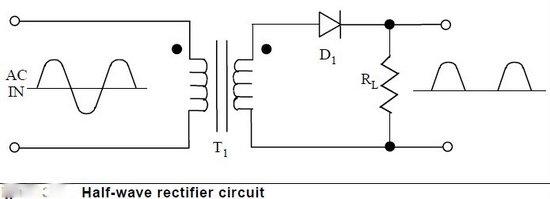
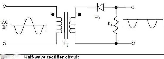
For a simple single LED, there is no benefit in my mind to choose the bridge, there is one consideration.  Some people can see the 60hz flicker of the LED when powered by half/wave rectification.  If you rectify it full-wave, the flicker is 120hz, and I've never seen anyone that can sense that.  Here's a comparison of the two waveforms.

The reason I selected full-wave rectification (bridge rectifier) for the lighting module sold through Henning's Trains is several-fold.

  • You have a higher efficiency rectification with full-wave, and it gives me greater flicker-resistance.
  • Half-wave rectification imparts a DC bias on the power supply if enough current is drawn.  While one lighting module may not be significant, a whole passenger train with lighting modules running half-wave might create enough of a DC bias to cause an issue.


Attachments

Images (1)
  • mceclip0

You don't NEED full wave rectification for any simple D-C device. A D-C relay will work fine, and so will an LED, on half-wave D.C.  We use full-wave rectification (which uses both halves of each sine wave cycle) and which creates UNFILTERED D.C. as the first step in creating FILTERED D.C for applications that require a SILENT or NOISELESS supply, such as communications gear (telephones, radios, some fancy battery charging circuits) or in circuits that cannot for some reason tolerate hum or varying voltage.

The steps are (1) full-wave rectification, and (2) filtering, using an electrolytic (polarized) capacitor in parallel with the supply output. The 4 diodes do the first "rough" work, so to speak, and the filter cap does the final "smoothing" work. The amount of capacitance determines the filtering result. More farads, more silence.  You cannot successfully/efficiently filter half-wave rectified D.C. 

The suggestion to Google some YouTubes is still my best answer. There are very detailed and easy to understand videos that explain all this.

Arthur P. Bloom posted:

You cannot successfully/efficiently filter half-wave rectified D.C. 

Well, that's not really true.  I'll agree with the efficiently part, but I do it quite successfully as does a host of commercial products.  Take the R2LC of TMCC fame, for instance.  How about the RailSounds universal power supply?  Both of these have a common AC & DC ground, that's not possible with full-wave rectification. 

I use half-wave rectification for my Super-Chuffer for the same reason, I need the DC ground to be the same as frame ground to be compatible with the TMCC signals.  In order to be as efficient as possible, I use a switching P/S module for my DC regulation, I just need larger capacitors than I'd probably need for full-wave rectification, the price I have to pay for the common ground.

BWRR posted:

The bias is coming becasue power is only being used on one side of the AC?

Correct, since you aren't loading one of the polarities of the AC waveform, it imparts a DC bias on the signal.  Obviously, the impedance of the signal figures prominently in how much DC bias is actually reflected.

In most cases, the minimal DC bias imparted by one or two LED's in inconsequential.  My only issue with the parallel diode is that the resistor has twice the power dissipation, but as you say, it'll work fine.

Of note, with two LED's powered from AC, you can simply connect the two LED's with reversed polarity to each other, that solves the reverse voltage issue as the LED's protect each other.  In this case, you're not wasting half the power in a diode, because each LED lights on one of the half-cycles of the AC power.

And to muddy the waters, a rectifier tends to be a large amperage device thought the dividing line is a fuzzy arbitrary.  FWIW I tend to call devices that need fasting with hardware, a rectifier, and devices that can just be soldered in using their wires, a diode.  Rectifier example:

Diode example:

Again arbitrary and fuzzy dividing line.  But in the end, they both accomplish the same end of changing AC into pulsating DC.

BWRR posted:

(I am a mechanical engineer rather than an electrical so I never quite fully figured this)

Then this might help, a diode is a check valve with a little bit of pressure drop (the 0.7 volts) in the direction of flow and no reverse flow allowed. I am not a mechanical engineer, but my working background was more mechanical.

I think the full wave and half wave has been covered above (not that I could explain if it wasn't). 

Basically, all diodes are rectifiers, but not all rectifiers are diodes.  There are other types of rectifiers as well, but they all do the same thing, only allow electricity to flow in one direction. (lets ignore the special cases like zeners for the moment.)  Generally using a single diode(or other rectifier) is used if you need to share a common ground with the AC input and/or you do not need a lot of current.  When used to supply  even slightly complex circuits a bridge is preferred because the filter capacitor can be much smaller.  Big capacitors cost a lot more and take up a lot more space than 3 extra diodes.  If your circuit doesn't actually need filtered DC, however, half-wave works just fine, costs less, and takes up less space.  

JGL

M. Mitchell Marmel posted:

To muddy the waters further, modern three rail trains use half-wave rectification to activate either the horn/whistle or the bell on electronic sound boards.  The horn uses the 'upper' half of the sine wave, while the bell uses the 'lower' half. 

Yes that does muddy the waters.    You said the bell uses the 'lower half'.  Where is the lower half on half-wave rectification.half-wave-rectifier-circuit.bmp


Attachments

Images (1)
  • half-wave-rectifier-circuit.bmp


rtr12 posted:
BWRR posted:

(I am a mechanical engineer rather than an electrical so I never quite fully figured this)

Then this might help, a diode is a check valve with a little bit of pressure drop (the 0.7 volts) in the direction of flow and no reverse flow allowed. I am not a mechanical engineer, but my working background was more mechanical.

I think the full wave and half wave has been covered above (not that I could explain if it wasn't). 


rtr12 I did have this bit understood, thinking of the diode as a check valve with a .7 volt pressure drop.  What I was struggling with was a combination of wanting to understand why we would select on solution over the other.

GRJ & JGL combined are a good explanation of some of the reasons why one way would be selected over another.

gunrunnerjohn posted:
BWRR posted:
I still have my first question.

In the for instance of a circuit to power LED's why would I choose a 4 diode solution rather than a single diode.
I am looking at the 5V circuit done on this forum, and the hennings 12V LED car lighting board.  In both cases a 4 diode solution was selected.  I had thought it was required to get the LED to work.  There must be another reason, I am wondering what that might be.

For a simple single LED, there is no benefit in my mind to choose the bridge, there is one consideration.  Some people can see the 60hz flicker of the LED when powered by half/wave rectification.  If you rectify it full-wave, the flicker is 120hz, and I've never seen anyone that can sense that.  Here's a comparison of the two waveforms.

The reason I selected full-wave rectification (bridge rectifier) for the lighting module sold through Henning's Trains is several-fold.

  • You have a higher efficiency rectification with full-wave, and it gives me greater flicker-resistance.
  • Half-wave rectification imparts a DC bias on the power supply if enough current is drawn.  While one lighting module may not be significant, a whole passenger train with lighting modules running half-wave might create enough of a DC bias to cause an issue.


JohnGaltLine posted:

Basically, all diodes are rectifiers, but not all rectifiers are diodes.  There are other types of rectifiers as well, but they all do the same thing, only allow electricity to flow in one direction. (lets ignore the special cases like zeners for the moment.)  Generally using a single diode(or other rectifier) is used if you need to share a common ground with the AC input and/or you do not need a lot of current.  When used to supply  even slightly complex circuits a bridge is preferred because the filter capacitor can be much smaller.  Big capacitors cost a lot more and take up a lot more space than 3 extra diodes.  If your circuit doesn't actually need filtered DC, however, half-wave works just fine, costs less, and takes up less space.  

JGL

 Then I had a light bulb moment, realizing as Arthur said I was mixing up what I think with what is.
I read some of the suggested reading a saw that I was thinking of the power after the rectification as being just flat DC rather than the half sine I was looking at.

Maybe the way I think of it is still wrong, I am not sure.  I certainly think I have a better grasp of this and why one would do one thing over another.

Thanks everyone for answering questions 


Add Reply

Post

OGR Publishing, Inc., 1310 Eastside Centre Ct, Suite 6, Mountain Home, AR 72653
800-980-OGRR (6477)
www.ogaugerr.com

×
×
×
×
Link copied to your clipboard.
×
×