
Folks,

I'm starting to install the many 154 highway crossing flashers that I've kept since my Lionel layout days back in the 50's.  I know the modern versions of this accessory have a switching circuit built in to alternately flash the lights...  none of mine do.

Back in the day we used the 154C connector to "flash" the bulbs.  But we weren't satisfied with the way they worked, so we made an "always on" flasher.  Since this was before any modern electronic switching circuits were available (at least to us kids) we decided to make a mechanical one.

Using an Erector set motor to turn a 4-inch length of broomstick, we placed brass upholstery tacks around the stick alternating them side-by-side about every half inch; we wired them all together and connected them to a brass strip wrapped around the stick. Next we built a wood frame with three wipers to contact the rotating stick; one rode on the brass strip to provide constant power to the tacks and the other two were positioned to alternately contact the tacks as the stick rotated.

Wiring was 14 volts from the transformer to the continuous contact wiper, while the other two got either the red or black wire of a twisted pair that alternately provided 14 volts to flash the lights.  Hook them each up to one of the bulb terminals on the flashers and all we had to do was use an insulated rail to operate the signal.  When train axles completed the circuit, the bulbs would alternately flash until the train had passed.

Once we had the red/black twisted pair working we could just run it around under the layout as a buss wire and hook up to all the other crossing signals.  If trains were coincidentally activating them all, sure they all flashed at the same time, but who cares... we were kids!

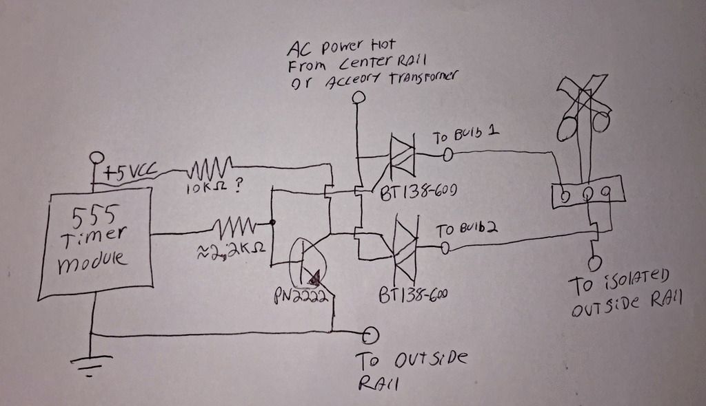
So with that as a background, is there a modern switching circuit that could provide the same alternating power to my new black/red twisted pair?  I've wondered if maybe there's an automotive flasher that provides the same wig-wag alternating between two flasher bulbs; like maybe the old fashioned turn signal flashers.  And would there be any problem with a modern electronic circuit if it had to power more than six or eight of the signals at once?  

I also wonder if there may be a modern circuit that doesn't even send power to the red/black pair until it detects that a ground circuit has been completed and the bulbs need to start flashing.  That way, it wouldn't have to be "always on", but I'm in way over my head now.  Any help from the electrical engineers out there, please?

Thanks,

Fj


Original Post

Replies sorted oldest to newest

The "Go to" device for crossing flashers for quite some time has been the LM555 timer.  This is a simple 8 pin integrated circuit chip, and is cheap and fairly easy to use.  The output of this timer chip can then be connected to transistors or relays to deliver the needed current to drive lightbulbs.   

Here is a basic circuit using LED lights: 

You're looking at less than a dollar in parts here if you buy through online suppliers.  

Another option that may or may not be easier for you is to use an Arduino micro-controller which will could do the same job as the 555 circuit with about 6 lines of code that can be directly copied from the very first example program.  Off brand Arduino's that could do this job (and much, much, more!) cost about $2.  With the arduino method you could use another $1 IR detector to trigger the device when a train is near, or two such IR sensors so that the signals turn on with trains coming from either direction.  

This other thread has some good information related to this.  

In either case, if you want to use light bulbs instead of LEDs, you will need something besides just the timer to power them.  I would probably go with TIP120 transistors, but relays would work as well.  

JGL

Sorry for the scribble drawing, but if you are willing to convert your 154 to LEDs, this circuit will fulfill the OP's intent of having one "master flasher."

First 555 is a standard astable, second 555 is used simply as an inverter/driver because the 555 output can both sink and source 200mA.

Voltage between wires A and B is basically VCC that reverses polarity. So, using two LEDs parallel opposed, with a single resistor, we can make the lights blink alternately with only 2 wires running to the 154. The 200 mA drive capability will let this circuit drive 10 sets of 20 mA LEDs, for example. For a single flasher you could use only a single diode and resistor.

If I was going to build this I would use a 556 dual timer, but I was too lazy to look up the pinout.

Attachments

Well, you've given me a lot to think about.  Unfortunately I don't have a photo of the original motor and broom device.  We were still grade school kids building a neighborhood layout in one family's basement where we could all run our Lionel trains.  And since we all brought our train stuff to be used, we had many of the crossing flashers to set up. so one of the smart kids who went on to become a physicist came up with the motor idea.  Now that I think about it, I still have a couple old Erector sets with motors... maybe I can just build a new version of our old "always on" flasher; I still remember what it looked like.

I've heard about the 555 timer/flasher before but assumed, maybe incorrectly , that it couldn't handle the current necessary to flash a number of  signal light bulbs.  And I'd rather not switch out all my old ones to LEDs at this late stage in my train life.

I appreciate all your suggestions and we'll see what I end up eventually doing; there's still a long way to go on the layout before I install the crossing flashers.  While I kind of understand the new electronics, and I think I still remember how to read a schematic, the theory of how some of this stuff works still confuses me.  And to think I started out in college to be an electrical engineer.  Whew, that would not have been good.

You guys are great, thanks

Fj

Another approach is to use low-cost eBay modules.  Many ways to do it but I figure 3 modules are required.  Less than $10 (free shipping from Asia).  Modular approach probably more expensive than component-level approaches proposed earlier but could save some soldering hassles and dealing with tiny components if these are not in your comfort zone.

1. AC-to-DC voltage regulator to convert 14V AC to 12V DC

2. 555 timer module running at 12V DC to cycle the relay to alternate flashing

3. 12V DC relay to module switch the 14V AC to the alternating lamp(s).  The relay shown handles 10 Amps which ought to handle multiple flashers.

ac isolated rail flasher using ebay modules

https://youtu.be/UXWkW9KDhR4

Attachments

Images (1)
  • ac isolated rail flasher using ebay modules
Last edited by stan2004

Going to York?  Look up Dallee Electronics in the Orange Hall....

They have a flasher, #367, that will handle two crossbucks with a 3 amp output...

https://www.dallee.com/Flasher.html

Or, if you'd like the bell sound to go with it...

https://www.dallee.com/GradeXing.html

...which includes a speaker.

If you're looking for a single flasher circuit that can handle more crossbucks, talk to Dallas.....perhaps he'll have some thoughts/solutions.

VERY nice people to talk/deal with!!

FWIW, always.

KD

Desert Railer posted:

Stan2004...can you provide a wiring diagram with how you hooked up the module...relays and regulator...

Each of the 3 modules come in different forms...such as with solder holes or with screw-terminals (for a bit more $).   I show the regulator as a combo of a bridge-rectifier (25 cents) and a DC-DC module (99 cents).  Or you get a combo module which has both components installed ($3).  Anyway, this should give you an idea of the connections.  If you undertake this, it's likely your specific modules, or the modules available at the time on eBay, may be slightly different.  If you provide specifics on what/which ones you have (photos always helpful), I'll try to comment if there's something requiring closer scrutiny.  This photo should be click-able to get more resolution.

14v ac insulated rail crossing flasher using ebay modules

Attachments

Images (1)
  • 14v ac insulated rail crossing flasher using ebay modules
gunrunnerjohn posted:
stan2004 posted:

Another approach is to use low-cost eBay modules. 

Stan, the king of the eBay modules! I love some of the mixes you come up with, there certainly are a lot of interesting building blocks if you look for them.

I will certainly agree here, he has some great ideas for using all this stuff. And he goes on to explain it to us, lots of great learning here as well. Some of my most favorite posts around here are on this electronics type stuff. Thanks to you and Stan both, and some of the others here as well. 

Desert Railer posted:

Thanks Stan...that was very helpful..all is clear...I did not see your email address posted in your profile. If you wouldn't mind, contact me through mine, so I can keep you as a reference.

I did not see your email in your profile either!  Just post your questions here and I'll see it sooner or later!

I am assuming the CW and CB refer to normally open and normally closed ....with the COW being the common. So does the 555 give an input that is more precise?...or is it already built in... thus that is why this device has adjustable timing? In other word, is a relay just a switch....and something has to tell it how quickly to change from NO to NC?  Perhaps this is a basic question....I am just not familiar with basic electronics. My email should show in my profile now.

Depends on which timer module you have.  I don't believe the one you show has "cycle timing" capability or turning the relay ON, OFF, ON, OFF, ON, OFF, etc. at some settable rate.  Most of the ones that look like your pic only have "delay timing" capability that turn the relay ON or OFF one time following application of power - they do not cycle.

There are relay modules that having cycle timing capability though I'm not sure I've seen any that use the 555 chip.  That is, they use a more sophisticated chip like a microcontroller and seem to use digital numeric displays to set the timing parameters with incredible resolution and range.  They seem to run in the $5-$10 range which is still quite remarkable.  Search eBay for something like "multi-function cycle timing relay".

Here's an example of one though I have not used this particular version myself.

s-l1600

I have posted previously showing hookup of a multi-function cycle timing relay module driving alternating crossing flashers and I can dig it up if you want to explore this avenue.  As for why use the 555 module at all when you can get a multi-function module (with relay) for not much more?  Well, not for this thread's application (driving high current lamps at crossing signal rates) but if driving just LEDs, using an electro-mechanical relay with 10 Amp contact not required...with the relay itself probably consuming more power than the LEDs!   And of course for faster cycling applications the 555 can operate thousands of times faster than a relay.

Note that the listings on eBay can be mis-leading in how they use the term "cycling" or "cycle timing".  I suppose one can argue a basic delay-on, or delay-off module is a cycle of 1 like a washing-machine cycle?  But really?!

Attachments

Images (1)
  • s-l1600
Desert Railer posted:

I am assuming the CW and CB refer to normally open and normally closed ....with the COW being the common. So does the 555 give an input that is more precise?...or is it already built in... thus that is why this device has adjustable timing?

The markings in the photo seem to be CK COW and CB.  This is a head-scratcher since relay modules for general purpose applications use the markings NO, C, NC (Normally Open, Common, Normally Closed).  In specialized applications like relays in cars you might see a different marking code on a relay module for the same functions.  This is just a guess by I'm think they may be using "K" for maKe, "W" for Wiper, and "B" for Break.  In electrical switches  the term Make is used when contact is made, Break is used when contact is removed, and Wiper might refer to the moving element that swings between the two contacts.  I'm just speculating so I'm thinking when the relay is activated the Wiper terminal connects to the Make terminal.  When idle the Wiper terminal is connected to the Break terminal.

The relays we're talking about here are basic switching components with no built-in timing capability.  Timing components such as capacitors, IC chips, or whatever must be added to provide that functionality.  And back in the day the most common timing component was in automotive turn signal flasher relays that cycled the relay based on heating and cooling of a bi-metallic strip.

So, the 555 is useful in running the AC lamps...because of their current draw. If it were LED lamps probably not necessary.

If you find yours  links for multi-function cycle relay timers...love to look them over.

If you have any more information on the keywords I should be searching on.. in Ebay Electronics to find the "simple device"....please let me know. I found the above module (I think)... for about $5.00 no shipping fee  It look like you program it using to K1 -K2- K3 buttons to control the NC and NO times. Perhaps, just running DC current to operate it , will be easy enough and should work in the AC Lamp Crossing Flashers...as it appears it can handle switching AC current. (thus using only two modules...the AC/DC converted and this)

Thanks again for the help...and the class in electronics.

Attachments

Images (2)
  • Relay
  • Relay Specs

Here's a pic from following thread showing such a multi-function cycle timing module.  There's a video in the thread too.

https://ogrforum.ogaugerr.com/t...92#41130793900088892

ogr%20ebay%20cycle%20timer%20module%20as%20crossing%20flasher

From what I can tell the module you found should do the trick using mode "P3".   So to your point you are down to two modules:

> voltage regulator module to convert Accessory AC to 12V DC

> cycle-timing relay module switching the AC voltage to the lamps

There may be hookup options once you have identify the exact modules.  For example, if you plan on operating multiple 12V DC items on your layout (timer modules, DC lighting/LED devices, whatever) it might be worth exploring ways to share a single converter module.  

Attachments

Images (1)
  • ogr%20ebay%20cycle%20timer%20module%20as%20crossing%20flasher
Desert Railer posted:

So, the 555 is useful in running the AC lamps...because of their current draw. If it were LED lamps probably not necessary.

You've got this one backwards.  The 555 by it's self will run several LED's without the need for a relay.  The relay is used to allow you to control higher current.  Most of the relay modules I've seen have 10 amp relays, which is enough for pretty much anything you'll want to do.  


Stan, the diagram you put together is perfect for a single crossing, but it doesn't look like it would work for  several signals as all of them would come on when any of them did.  This is fine if you use a set of modules for each set of signals, but if you wanted to use one controller for all of the signals it would be set up a little differently.  

To use one timer set-up for all the signals you would have to either leave it constantly running, or devise a way to isolate each isolated rail trigger from each other, perhaps with diodes.  I think that simply leaving the device running would be the simplest solution, then you only need to use the isolated rail to connect the common terminal of the bulbs.  

This has two disadvantages, however.  one is that the relay will wear out much quicker, though it will still last quite a while.  the second is more of an issue with the cheap relay modules than many other relays.  They are loud, and having the relay constantly clicking when the layout is powered up could get annoying.   the first thing I thought of to solve this is using solid state relays, but the cheap modules that are out there with solid state relays have two problems.  they are only SPST and are rated for just 2 amps.

Another option would be to use power transistors or Triacs on the output stage, depending if you wanted to power the light bulbs from DC or AC.  

I know it is a little more complex than just using the 555 and relay modules, but instead of switching the relay module from the 555, you could instead connect the output to logic-level triacs...   Heres a rough sketch of what I have in mind.  The triacs I have here cost about 50 cents each.  they are rated for 12 amps current, and the 555 should provide plenty of current for the logic-level gates.  the PN2222 transistor is used to invert the 555's output to one triac, so that when one is on, the other is off.  I just guessed at values for the pull-up and current limiting resistors.  

JGL

If you're still interested in making this circuit, an Astable Multivibrator will probably do you the best.  Now for the components...  A 555 chip is a tank, but it really depends on how long you're planning on running your trains if it is always on.  Robustness of the 555 under a constant draw is generally not the best idea from a design perspective.  Especially if you run your trains for extended periods of time and whether, or not you want to spend some time under the layout every now and again.  If this is the case, there needs to be thought about how to mimic what is in the 555 that causes oscillation.  Here is what is inside a 555 chip. 

Image result for 555 design inside

You can mimic this using a couple of NPN transistors that are not only cheaper and more robust, but the extra features of the 555 that aren't being used do not go to waste.  It looks like John has already given you a bit of a head start.  The main principle of a NPN transistor multi-vibrator is connecting the bases of the transistors to 2 equal valued capacitors (In this case the same value for an even flashing rate) and send that node to one bulb post of the 154.  This way the cap charges and causes the base connected transistor to reach saturation.  This then causes  this transistor to discharge all current to ground and the opposite bulb to shine.  Current on the next branch builds up until the next transistor reaches saturation and then forces all the current through the other branch illuminating the second bulb while the first bulb has no current. This is what's called an oscillating circuit.  Specifically, a multivibrator with NO STABLE STATE (Hence the name Astable).  If you have any questions feel free to reach out.  Multivibrators are quite literally IC design and there is a lot that goes into perfecting it.  However, the circuit is as fool proof and robust as any cheap circuit could be.  Just my opinion.


James

Last edited by Datdupa46_Novotronics

? an automotive flasher? More load increases the speed. You might use two signals, different bulbs, resistor(s), etc. to dial it in. 

If it also powered a small relay you could alternate L&R lamps.

There are turn signal relays that do alternate, but I don't know the number or if they are even made anymore (the vw version is not)

Just wondering if there were any new packages, like the TIU tester, track detector, etc., that I had overlooked.  I want to make up some LED flasher crossing signals; the commercially available signals are too pricey and I like to assemble kits.  There are so many modules coming out of China that it's hard to keep up.  Like Stan's 2016 3-module setup above.

A great source of electronic circuits you can build for model RR devices - in addition to all the great advice from Stan, John and others here (of course !) - is Rob Paisley's (new) website, here:  http://www.circuitous.ca/CircuitIndex.html  -- its a new URL but it apparently has all of the information his old site had along with all the updates and new ideas he offers.  As someone else noted on this thread, there's also going the route of using a micro-controller like an Arduino or similar to do mostly in Silico what you'd ordinarily do with specific circuity designed for specific tasks (e.g., flashing grade-crossing lights, etc.).

As this thread is 3 years old I guess it's fair game to diverge from the original topic of the PW 154 with 2 red incandescent bulbs.

154 bulb red

From what I can tell the circuits offered by wehonest are meant for driving LEDs (as opposed to power-hungry bulbs).  In the OP's case, the question was asked on how to simultaneously drive a half-dozen flashers … so over 1 Amp since each bulb is apparently rated for 0.2 Amps.

So to continue the discussion (and I realize I may be talking to myself now ), it seems one must make the choice to convert to LEDs or stay with the original bulbs.

1) LEDs.  I recall seeing a thread where someone simply replaced the bulbs with suitably sized red LEDs and re-wired to be driven by one of the many DIY or off-the-shelf LED-capable flasher circuits.  I suppose one could hunt down if someone makes a screw-base LED equivalent bulb and confirm the 3-terminal (one common terminal) wiring is compatible with the chosen flasher circuit.  

2) Bulb.  The 2-module relay approach ($5) I showed could handle simultaneously driving a handful of flashing bulbs.  But the relay method does have the potentially bothersome clicking on each flash.  To that end, there are solid-state-relay modules on eBay for, say, $1-2.  These could be used with a low-current LED flasher circuit to "boost" the current switching capability to more than 1 Amp.  Here's an example of a DC buffer (using a FET) and an AC buffer (using what is effectively a triac).  The latter would be used if you want the bulbs driven with, say, 14-16V AC Accessory voltage.

dc ac solid-state buffers

So the low-current DC flashing (on-off-on-off...) control signal from the LED flasher module would drive two buffers (one buffer for the left lamp(s) and the other buffer for the right lamp(s).  There's some i's to dot and t's to cross to get the polarities, voltage levels and such in order, but I think it could be done without soldering which I'll arbitrarily declare as the line-in-the-sand.  This would be silent running.

-----

Separately.  A potential bonus with using a buffered (high power) flasher circuit is you can share the flashing function between multiple signals.  

154 flasher multiple

So rather than having to buy one flasher module per 154, you share a single flasher amongst multiple gates triggered by the common terminal of the 154(s).  The downside is you have to run the orange and red (i.e., left and right "hot" lamp signal) wires from some central point to wherever a 154 is located.  And, perhaps obvious, when multiple 154s are flashing, they do so in unison.

Attachments

Images (3)
  • 154 bulb red
  • dc ac solid-state buffers
  • 154 flasher multiple
Last edited by stan2004

Add Reply

Post

OGR Publishing, Inc., 1310 Eastside Centre Ct, Suite 6, Mountain Home, AR 72653
800-980-OGRR (6477)
www.ogaugerr.com

×
×
×
×
Link copied to your clipboard.
×
×