Great forum.  Finally joined.

I have scratch built a O scale turntable for my grandson's layout which is operating with a arduino uno, stepper motor and associated motor drivers. I am currently converting all of the conventional control of the layout to DCS and am wondering if anybody here has(how) successfully connected a arduino to the AIU for stepper control?  The turntable functions now with push button control but I want to eliminate that and use the functions of the DCS remote through the AIU. Any input is appreciated.

Original Post

Replies sorted oldest to newest

I believe this gentlemen's work would enable you (with a little additional effort on your part) to "spoof" a tiu in such a way that a remote could communicate through it to your arduino set up & make your turntable turn:

See here: 

http://www.silogic.com/trains/OOK_Radio_Support.html

And here about 3/4s of the way to the bottom of page on this topic:

"RTCEngine - A program which emulates an Engine connected to a TIU. It outputs the commands it receives and responses that it sends to the Arduino IDE Serial Monitor Port. Look at Technical Video 7 at http://www.silogic.com/trains/Technical%20Videos.html

    RTCEngine  - panStamp version
    RTCEngineE - Infiduino/ElecHouse CC1101 version"


One AIU-based approach would be to use 2 AIU accessory outputs.  One for CW, one for CCW.  Your "manual" inputs to the Arduino may be configured to operate this way, but have the Arduino sense the 2 AIU outputs.  If the output is "on" for less than some interval such as, say, 1/2 sec it advances the stepper motor one step.  If the output is longer than 0.1 sec it starts slewing the stepper motor to rotate the table as long as the button is held down.  This allows you to use either the latched or momentary modes of the AIU accessory output as shown on the TIU remote.

If the Arduino already has a inputs/sensors from the turntable that already stops it when the tracks are aligned then the same software could be used.  Obviously it would ignore the auto-stop if it sees the AIU output still active...knowing that you want to "skip" the particular track and continue rotating.

Great info, thank you. But not wanting to go to that direction. I'll leave that to the grandsons when they find the key to the breaker panel.

 What I am thinking(careful).  Connect a AIU switch port, pins 1 & 2 (keeping the N pin negative) to respective analog pins on the arduino. Use the switch functions on the DCS hanheld to energize the arduino.  I have written a sketch for the arduino that indexes the stepper motor to 9 positions and a home station.  Thinking the curve and straight button of the switch function of the DCS handheld would work  for the arduino to move the stepper to the first index point by pushing the straight button and then the  curve button to return home.  Connect more AIU switch ports as needed for the remaining index spots for the turntable.  Could it be that simple? I tend to miss the simple and don't realize it till I have overbuilt.  My extras stash is getting out of hand.  Any thoughts or ...?

I don't have an AIU, but I assume the switch outputs are two separate momentary contacts. If so, you probably want to wire the turntable using the switch outputs of the AIU.  That way, you can control the turntable with the two softkeys (through/curved) displayed for a single switch on the DCS remote.

The accessory outputs are a single relay (NC/NO contacts), so if you wanted to replace the function of two pushbuttons with the accessory outputs, you'd have to keep selecting a different accessory to 'push' the two different buttons with the remote.

So I'd just wire the two connections on an AIU switch port to close the same circuits your two pushbuttons close.

(Assuming you have only two pushbuttons)

Stan2004, thanks, spot on.  I 'll make some adjustments to my sketch and go for it.  I will post the results. Have 10 more switches to wire with tortoise motors and relays first. The arduino and turntable are in my line of sight and mind every time I lift my head from the current layout work. Gotta throw a towel over it so I don't mis wire something.

MRR has come a long way from when I was kid cranking the handle of a transfomer and pushing buttons.

Try the simpler approach first.  If not satisfied, the "panstamp" approach on that webpage I posted would allow you to (for example) use the speed control to map to 10 turntable settings.  Or you could use any remote command(s) you wanted. (if I understand what you after:  home, 1 - 9 additional turntable positions - so speed commands 0-10 or whatever you wish would do it...)

I have one of the panstamps and it works great.  But I do no use the "RTCEngine" program -- instead I use the "RTCModem" program to create a computer interface to command my engine.

But for this application, you'd need to get the code for RTCEngine from the website and do a bit of your own rework on it to get it just how you want to make the remote and turntable work together as desired... (& of course the related hardware and all that)

There are better ways to do this, but the simplest solution I can think of is to use two of the accessory outputs of the AIU.  Turning one on would advance the turntable clockwise, and turning the other on would advance it counter clockwise.  The Arduino would then be programed to stop the table at the next track location from where the accessory output is turned off.  You could use a third ACC output to trigger a home button as well, or perhaps program so that if both (CW/CCW) acc outputs are turned on it will return to the home location.  Overall, not the most efficient method, but it would do the job.  

JGL

JD RR posted:

...Connect more AIU switch ports as needed for the remaining index spots for the turntable. 

Hmm, this brings up another scenario - directly specifying target position so you can "fire and forget" rather than having to baby-sit the controls until the operation completes (i.e., 1 minute if you have a 1 RPM table).   While I suppose you could use 10 switch or accessory connections of an AIU to specify your 10 target positions, how about just 1 (or 2)?

Since you say you "know" the home position I presume then that the Arduino has some kind of feedback as to TT's absolute position.  Maybe on initial power-up you rotate the table until you find home.  Anyway, suppose you have the Arduino drive a visual indicator of the target position.  This could be 10 discrete LEDs mounted in a circle on a control panel mapping the actual TT positions.  Or it could be a 7-segment LED showing 0..9 with 0 being home.  A single AIU output is connected to a single Arduino input and the Arduino advances an internal counter on each input pulse rolling over from 9 to 0.  The counter value is reflected onto the LED indicator.  This allows you to set the target position in a few seconds.  Then the Arduino takes over the drudgery of slowly stepping the table to the final position while you sit back and enjoy a cup of coffee.  If you use 2 Arduino inputs, you could use a single AIU switch output to count-up on a Straight pulse and count-down on a Curve pulse.

This method is also directly compatible with your manual controls.  You could even wire them up in parallel so you could have both DCS-remote and manual push-button control.

Arduino inputs/outputs are "cheap" relative to AIU outputs! 


Sometimes the KISS principal it is the best. I had set up our  TT  as an engine and could control it with the dcs remote or cab-1. (AC delux from digital dynamics) However I found it much easier and reliable  to use a DPDT center off toggle (wired like an HO reversing switch) to control the stops by the eye ball method. A second smaller DPDT  center off momentary  toggle  in parallel   for fine tuning. Yep we're all different and like to try other  methods.

Stan2004, At present home or "0" is written into the sketch. One push of the button sends the table to the first index. 2nd push returns it back to "0" and so on for each of the six buttons. I am using a Pololu 200 step per rev stepper wired bipolar.  This motor slows down and smoothly stops at each pre determined index(degree of revolution) with 0 drift.  I like your idea of only tying up one of the AIU ports to achieve the goal. Since the turntable has been down due to relocating it, my counterparts (grandsons) scavenged the switch panel for use on another small three rail for their learning experiments.

Another option that could work very nicely would be to run the turn table as a TMCC engine.  Rather than using any AIU outputs the Arduino could be connected to the TIU's serial port and be programed to look for commands issued to a particular TMCC engine address.  From the DCS remote you could then press any of the 10 number buttons to tell the turntable to move to that number's assigned track.  With a little more programing you could do things like making the turntable speed adjustable from the thumb wheel or use the Whistle, bell, and direction buttons to operate added features.  

There is a little more programing involved, but this would give the option of set and forget indexing, and moving the table to your desired track would only take a couple of key strokes on the DCS remote.  

If you decide this might be a route to take, I have working code to read TMCC commands into Arduino that we can fix up for your purposes.  

JGL

With the cable length it shouldn't be an issue... but might be.  I believe, but would have to confirm, that the TIU uses something close to true RS232 standards which is a +/- 15 volt signal.  The 'high' voltage swing is specifically designed for long distances.  The original TMCC base used a simplified RS232 protocol with only 0/+5v swing which might drop off at a 15 foot distance.  Whatever the output of the TIU is, you have the option of placing the RS232 to TTL converter at whichever end of the cable makes more sense.

As a gut feeling I don't think 15 feet or so will be a problem.  If it turns out that it is you could also build a very simple 'signal booster' with a transistor.

JGL

Going back to the panstamp solution which spoofs a tiu -- the remote connects wirelessly to it as any other real tiu.  (referring back to -- http://www.silogic.com/trains/OOK_Radio_Support.html)

Marrying the panstamp to your ardiuno could be easy -- there's a usb port on mine although it also gets power from it -- so there's some details to sort through there. (ok, to be fair nothing is easy.  how 'bout easy-ish with luck...?)

Mark's RTCEngine hard codes it to TIU#4 and you can decided what to return on "read" --- well how about "Turntable001".   (Maybe you'll get two one day.)

After that it's a little more code to decided which remote commands to map to what turntable function and how to tell your arduino to implement them the codes come over as text -- and those are all explained on Mark's website.

On the remote, the thumbwheel is one idea for turntable position, smph 1 for position 1 and so forth...  but that's up to you to decide.  Any remote codes you wish to map to the turntable commands is something you'd configure in your "tiu spoofer/ardiuno" code base ...

There's no cable except possibly between the panstamp and your arduino although maybe there are options to do away with that too.  Power -- wall wart for panstamp, but battery is an option.  Possibly the panstamp and arduino are powered off the same supply or same battery back...?


I think what JD RR needs to know is exactly how to connect the TIU 9-pin Serial Connector to his Arduino.  Even though the TIU connector is labeled "PC Input (RS-232)", I believe RS-232 is referring to the TIU-to-PC interface.  The TIU-to-TMCC connection is the matter at hand, whether that interface can handle a 14 ft drop, and what additional components/modules might be needed.

Should he buy the $25 (MSRP) 6-ft TIU-to-TMCC 50-1032 MTH serial cable?  Also, depending on which Arduino module he has I'd think there could be some considerations.  If the Arduino shares its single serial port with an onboard serial-USB converter, can he still directly patch in the TIU signal?  Or what if his is a 3V Arduino - is that directly compatible with whatever comes from the TIU?

Separately, has anyone cobbled together a Arduino-based TMCC command-base emulator that converts the serial input (e.g., from a TIU) to the 455 kHz track signal?  Seems this could be done for under $10 and not much new software (JGL earlier suggested he has the input-side solved) - though I realize Nothing is so easy as the job you imagine someone else doing.

I intentionally didn't get into much detail for a couple of reasons.  First I didn't figure on spending much time on it if this method wasn't going to be considered as an option.  I also tend to get carried away with details that are more than needed.  

What would be needed is an RS232 to TTL converter.  You can use something like a MAX232 chip for this, but for a one-off design I would go with a pre-made module like this one:  

These cost $2.00 shipped from china.  

In addition one could use the MTH cable, but any standard null modem serial cable will also work.  

While one could use any arduino where the tx/rx pins are not being used for anything else, I would use a Mega2560 which has several sets of tx/rx pins, at least for testing, so that the first set is still open for the arduino IDE's serial monitor.  This would allow easier debugging.  WEven with an uno or nano or some such at the 9600 baud of the TMCC protocol one could probably get away with using the software.serial library as well.  

I'm happy to supply more details as needed.  As for the TMCC-Arduino link up you can see it in operation on my TMCC to LionChief bridge here: https://ogrforum.ogaugerr.com/t...-tmcc-is-it-possible

JGL

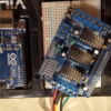
Ard and MS          Thanks to all for sharing your knowledge. Pic of boards I am using to run the table. Arduino UNO and Adafruit motor shield v1 which is no longer available as they have upgraded to v2.

 I have both, DCS and TMCC. Primary setup is DCS. I need to sort through the pros/cons  along with a bit more reading/research/testing to do and decide which direction to go.   15 days before the operating crew arrives for the summer. 

Attachments

Images (1)
  • Ard and MS

I've been meaning to actually measure the AIU relay timing but finally got around to it. 

If you go with the AIU approach you have the choice of using a SWITCH output or ACCESSORY output.  The pulses you get from the SWITCH relay output appear to be exactly 0.5 seconds.  The pulse you get from the ACCESSORY relay output are as long as you hold down the "ACT" button; the shortest time I could get was exactly 0.2 seconds.  This might help you in writing an Arduino sketch.

Add Reply

Post

OGR Publishing, Inc., 1310 Eastside Centre Ct, Suite 6, Mountain Home, AR 72653
800-980-OGRR (6477)
www.ogaugerr.com

×
×
×
×
Link copied to your clipboard.
×
×