I have read that modern equipment uses a 1.5 volt dc positive offset voltage to activate horn/bell sounds. 

If I set up a series of isolated track sections with this offset voltage coming from a seperate small transformer, like a small regulated dc power supply stepped down to 1.5 volts...what I have in mind is the approach to a crossing, to automatically simulate the horn of a train approaching the crossing...will I damage anything?

Last edited by gibson man
Original Post

Replies sorted oldest to newest

I would be interested in trying this - never heard or read of it before.  But I want to make sure that I understand.

The 3-rail track with the insulated rail has AC track power running thru it at all times for the train to use (thru the center rail and the non-insulated rail).  BUT... it also has about 1.5V DC being fed to it at ALL times too.

I can't visualize where the 2 wires connect onto the track from the DC source, using a lockon as I would do.  Would i need 2 lockons, one connected to the insulated rail and the other to the other outside rail?  I'm also assuming that the center rail has to be the recipient of the DC voltage so that the pickup roller can pick it up to blow the horn.  How do I do this?

Next question: if I use a small DC trannie set to 1.5V DC, do I have to be careful IN ANY WAY how it connects to the track relative to the way that the AC trannie is connected to the track.  Even tho' I THINK phasing isn't an issue here (it's my understanding that phasing is an AC only issue), but make my question more general - is there anything to be aware of???

As always, thanks - walt

Last edited by walt rapp

Using diodes alone would work too, but at the cost of a slight voltage drop.

New and old are triggered by offset. New stuff, a positive offset triggers horn/whistle, negative triggers the bell.(if equipt) The old can't tell a difference  and triggers on either.

Roy is right too, you might want to add a bypass switch too


gunrunnerjohn posted:

The DC source has to be in series with the AC track voltage.  That being the case, the DC source also has to have the capability to support the current draw of whatever is running on the tracks.  If you have a locomotive that draws three amps, you need a 3A DC supply in series with the AC supply to trigger the horn.

Can you point me to a detailed analysis of using a regulated DC supply for this application?  I can understand the battery method since the horn would only intermittently charge a primary-cell (when AC track voltage changes polarity).  But a typical regulated DC supply has a polarized electrolytic capacitor on the output; it seems charging/discharging 3 Amps (or whatever) thru this capacitor requires additional consideration.  For a typical regulated supply, the other circuitry in the regulator can only supply current to the capacitor; there is no current path to discharge the capacitor (when AC track voltage changes polarity).

Last edited by stan2004

Stan, why do you keep putting me to the test.   The regulator does discharge, or when I turned the voltage down on the supply, it couldn't reduce the voltage with no load.

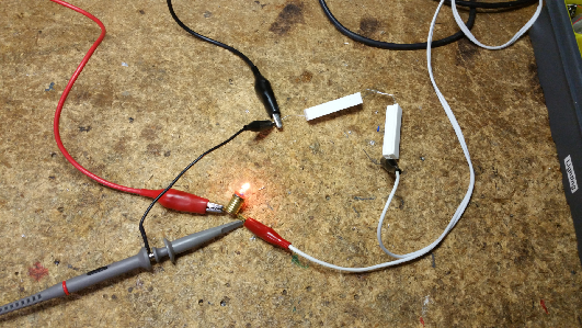
Here's a kludge on the bench just to test it.  The white leads are my DC power supply, the B/W leads are from a Z1000 transformer.  The load in this case is the light bulb.

The waveform is the typical chopped waveform from a Z-Controller, but the DC bias is obvious.  The first picture is with a 1.5V setting on the DC supply, and the second picture is with a 10V setting on the power supply.  As you can see, the DC offset shifts the baseline up.

DC 1.5V on ACDC 10V on AC

Attachments

Images (3)
  • blobid0
  • DC 1.5V on AC
  • DC 10V on AC
gunrunnerjohn posted:

Stan, why do you keep putting me to the test.

But you didn't submit your findings using a #2 pencil!

I was only inquiring if you knew of a more detailed analysis of using a DC power supply (vs. the battery or diode methods).  For example, consider the suggestion of using a 3A DC supply if loco draws 3A AC,   Presumably that's 3A RMS so the actual peak current into the loco might be 4A, 5A, or more particularly with a chopped transformer.  Does that mean you should really provision for a 5A (or more) DC supply?

Anyway, it would be great if some guys who have successfully done this would report-in exactly what they used.


Let me work on the #2 pencil.

Yep, I think the diode chain in series is probably the way to go, specifically this configuration.  Close Open the momentary switch to disable the automatic whistle.  The only consideration is you'll need about 4 to 4.5 volts more AC feeding this isolated section to maintain the same speed.  That would indicate a separate transformer, but it's cleaner than fooling around with the DC supply.

Attachments

Images (1)
  • blobid0
Last edited by gunrunnerjohn
gunrunnerjohn posted:

Let me work on the #2 pencil.

Yep, I think the diode chain in series is probably the way to go, specifically this configuration.  Close the momentary switch to disable the automatic whistle.  The only consideration is you'll need about 4 to 4.5 volts more AC feeding this isolated section to maintain the same speed.  That would indicate a separate transformer, but it's cleaner than fooling around with the DC supply.

Don't you mean OPEN the switch to disable the whistle?

So...the idea was to have a somewhat prototypical - automated- horn-blowing approach to a crossing...

An electrician guy I was talking to made me think that, when the train crosses into the circuit with the dc offset on it, as long as the train (engine, cars, etc) are in the isolated section, the dc offset will be transmitted throughout the entire track run until the ENTIRE train passes the isolated section...meaning I wouldn't really get the short horn actuation on approach I am trying to get.

I am after this...toot...toot...T-o-o-o-o-o-o-o-o-o-o-ot...something along the lines of a 1 second blow...a 3-4 second pause...a 1 second blow....a 3-4 second pause...then maybe a 3-4 second blow as the train crosses over a grade crossing...

So...now people are talking about proximity switches, relays, timers, etc...and it's getting more complicated than I really wanted it to be.

Maybe I'll just stick to a manual switch...

I haven't heard from Dale H in a bit, but here's a link as to how he did similar with relays. It and discussion on it, have been posted here before if you searched around. This could be triggered automatically or by button if I remember right.

If you have your heart set on it,, don't give up. It's not really simple, but not hard either, it's just new to you.

Well, if cobbling together relays, timers, etc. is not in the cards, how about a sound-module with the pre-recorded sound of your desired short-short-long diesel Horn sequence.  I realized different engine have different Horns but arguably not a varied as steam-whistle blasts.  MP3 players are insanely (low) priced on eBay...maybe $2.  So it's a different sort of cobbling - wiring together an MP3 player, speaker, trigger, etc. though probably a bit cheaper than multiple relays and timers. 


If you are running MTH DCS and you program a "route" or a "scene", and you blow the whistle manually during the programming session, will blowing the whistle be programmed into the route at that point and then happen automatically when the route is run?  

Don't see how the OP's quest for two-short, one-long whistle sounding automatically at crossings can be satisfied without some kind of pre-programming feature like DCS.

Think I stumbled onto the solution...build a diode string...use AZATRAX IR detectors and relays to control it...three detector/relay/diode strings inserted at three different locations...since the IR detectors are able to be custom-timed from the manufacturer, I can get the length of horn activation I want...I think...

Thanks for all the input...I asked a lot of people a lot of questions...

gibson man posted:

...three detector/relay/diode strings inserted at three different locations...since the IR detectors are able to be custom-timed from the manufacturer, I can get the length of horn activation I want...I think...

I'd be curious to see if this custom-timing done by the manufacturer adapts to speed; for typical IR detectors the timing is done by the end-user but only to a single value (time interval).  So done the typical way, the effect will depend on how fast the engine is going....go twice as fast and the 2nd and 3rd toots will get triggered twice as fast (unless accounting for speed). 

It would be neat if the custom-timing capability also supports directional logic/lock-out.  If you have detectors on either side of a crossing presumably you wouldn't want to trigger a "backwards" long-short-short sequence when the engine passes the crossing and trips the detectors on the trailing side.

Last edited by stan2004
hojack posted
Don't see how the OP's quest for two-short, one-long whistle sounding automatically at crossings can be satisfied without some kind of pre-programming feature like DCS.

Dale did coin op/ pinball repairs. Its based on old electrical tech vs modern, which is pretty much the same only in a smaller package. You should readup on how Dale did his, it could work on post war as well as new if I remember right. I.e. I don't think he used an "external" whistle horn. Even if he did, he likely spills the beans on how to use the train itself too.

Add Reply

Post

OGR Publishing, Inc., 1310 Eastside Centre Ct, Suite 6, Mountain Home, AR 72653
800-980-OGRR (6477)
www.ogaugerr.com

×
×
×
×
Link copied to your clipboard.
×
×