Hello Trainmain2001,
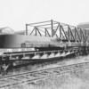
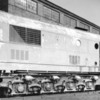
These photos you have posted are really amazing.
I have a lot of interest in this loco, but there is little info about its construction that I have been able to find. I queried the PRRTHS, as well as PA State Archive in Harrisburg, Pa. Both claim to have some amount of Baldwin archived photos and drawings, but not cataloged in a manner that allows quick/easy access. I will pay a visit to the PA State Archive sometime when I'm up in the northeast.
Meanwhile, I came across this forum, and what a treasure you have posted here.
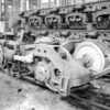
One detail I am really wondering about is how the front and rear truck frames articulated.
I did find a set of photos similar to the ones you posted here, on another web site
(http://www.trainweb.org/seaboard/CentipedeProject.htm). One photo there shows the two truck frames are pined together where they meet at the center of the loco. It appears this forms a hinge; there is no floating mechanism on either half of the joint to allow any axial (along the length of the loco) movement as the two trucks pivot. It also appears from tha photo, there is no attachment to the loco frame above this hinge point. Rather, as the trucks pivot, the truck frames are free to swing outwards (right or left depending on curve...). So, something has to give somewhere or the trucks could not pivot.
Also, I can't tell from any photos I've seen, where the pivot point of each truck frame is located. I would guess somewhere outboard of the end-most wheel (axle), at the opposite end of the truck frames from the hinged end. But exactly where and how that pivot point works is still a mystery, especially given the two trucks are pinned together at the center.
Do you by chance have any other photos are even drawings that might show how the truck frames were "fastened" to the loco frame, and where the pivot point is located?
Again, thank you for posting these terrific photos.
Best Regards.
ES.


