Guys,

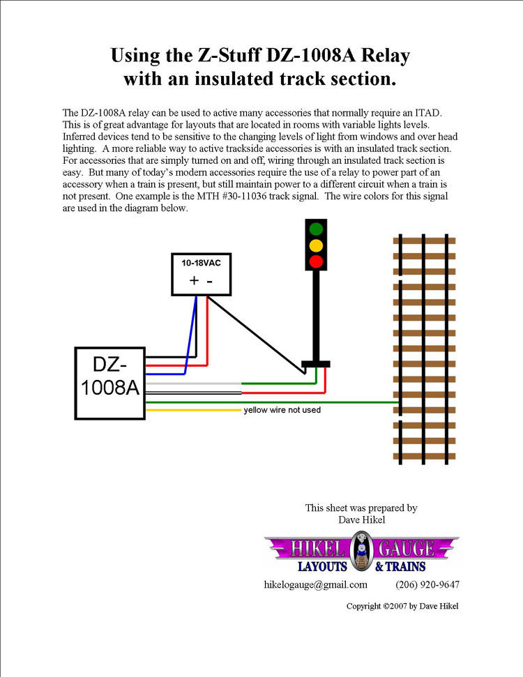
I am installing my first block on my layout.  I have a mth cantilever bridge signal and z stuff 1008A relay.  When the train enters the block the red lights come on but the greem light remains on as well.  Then when the train exits the block the red goes out and the green ligh remains lit.  I never get amber at any point.  I am not great at electrical.  Any idea what I have wired wrong?  Have severl more blocks I want to do once i master this one.


Thanks,

Mike


Original Post

Replies sorted oldest to newest

I realize the green stays ON all the time, but do you at least get the amber for ~10 sec when you initially turn on power?

And assuming these diagrams from the MTH and Z-Stuff signals are what your have, what exactly are your connections between the 3 MTH wires (black, red, green), the 6 Z-stuff wires (red, black, green, blue gray, white) and the track/transformer?

Untitled

Attachments

Images (1)
  • Untitled

I worked on this all day and found a schematic on the forum yet not there yet. At this point I finally got the lights to change. When the car enters the block it turns from green and then red and amber then green again as it supposed to.  Now my problem is that I lose power once I enter the block portion. I have a common soldered at the beginning of the block and another in the center of the track section as soon as it gets past that track with the solder insulated rail the signal it loses power and no longer the signal goes amber to green well before the next fiber pin.  I have nothing soldered to the center rail.  I now need to work on the block as I am not doing something correctly. I followed the schematic below exactly other soldering another common wire after the block begins to the insulated rail.  This my first block so definitely a learning experience for me.


I have the block signal lights working perfectly in moving to the center rail for isolation just as they should and operate in the entire block. Yet still have no track power when I push a car into the block.  Any ideas what I am missing here?  I suspect it might be related to my dcs signal running through the center rail. I have a 22 gauge wire soldered to the center rail and connected to the green wire coming out of the relay. I have tried connecting a wire from the tiu still does not work. Somehow I probably should get power to the block from the tiu but don't know the proper connection.


I worked on this all day and found a schematic on the forum yet not there yet. At this point I finally got the lights to change. When the car enters the block it turns from green and then red and amber then green again as it supposed to.  Now my problem is that I lose power once I enter the block portion.

Kind of sounds like you outside rail   power supply is on the same side as the insulated track section.  Move it to the other rail...

Chuck,

I am using all ross track and switches.  I took some pictures.  Where the two cabooses are sitting is the beginning and end of the block.  I one power feed from the tiu into the section where the large black pennsy signal bridge is located.  I am only talking about the outer track. I only have one switch for a siding but does not have any impact as tried it with just a straight removing the switch.

IMG_1330IMG_1329IMG_1328

Attachments

Images (3)
  • IMG_1330: The block
  • IMG_1329
  • IMG_1328: Section with block

Mike,

There could be more  than one issue here.  First, it looks like the Hikel wiring diagram will just control the light, not track power.  Secondly, if the center rail is powered and the non-insulated outside rail are both continually powered as shown in the diagram, the train will never stop in the block.  Third, if the non-insulated outside rail is not powered, the train will stop when it hits the block.  At this point the light may change but not because the wheels connect the two outside rails.

Steve

shorling posted:

Mike,

There could be more  than one issue here.  First, it looks like the Hikel wiring diagram will just control the light, not track power.  Secondly, if the center rail is powered and the non-insulated outside rail are both continually powered as shown in the diagram, the train will never stop in the block.  Third, if the non-insulated outside rail is not powered, the train will stop when it hits the block.  At this point the light may change but not because the wheels connect the two outside rails.

Steve

Why would you want to have the track power dead?  

I do want power and did not realize this until Steve saw it in the diagram.  I have a power feed into the block and got the power to run continously but now the signal light won't change.  I just wrote an email to z-stuff as I have tried every imaginable way at this point.  At wits end.  I really don't want to use IR sensors as the light in the room impacts it at times and a block is more prototypical

Mike


This should be a piece of cake but it's not.... It would be really easy to do the  hook up with an AC relay or with a DC relay with full wave rectifier but I can't find out how the DZ-1008 actually works. I believe it's a SPDT   (single pole double throw) but it's difficult to find out what wires do what... or what voltage the thing works at.

It's going to work but We need a little more info....I couldn't find much on DZs  web site. good luck


Thanks for everyone's help.  I finally got it to work.  So I thought I share how I did it for others who have s issue in the future.  Z-stuff sent me the diagram below.  In addition since I run my accessories on another transformer I had to ground one transformer to the other.  I got that tip from Eric Siegel. Then I had to solder a wire between the outside rails in the track before the insulated pin.


Attachments

Images (3)
  • Z-stuff diagram
  • MTH cantilever signal
  • Pennsy Signal Bridge

Add Reply

Post

OGR Publishing, Inc., 1310 Eastside Centre Ct, Suite 6, Mountain Home, AR 72653
800-980-OGRR (6477)
www.ogaugerr.com

×
×
×
×
Link copied to your clipboard.
×
×