
I have several blocks on my layout for signals.  My track is O Gauge Tubular and I use the basic outside control rail and relay to change signal from green to red when there is a train in the block.  They have worked quite well for several years.  My signals are scratch built out of styrene with Radio Shack LEDs.  Some are 2 color signals Green over Red.  And some are searchlight signals using Radio Shack 276-0028 LED that will display green or red.


Here is a picture of one of the Seachlight signals.


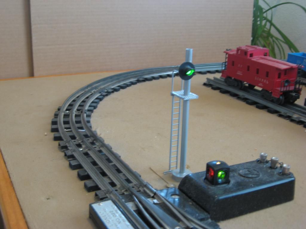
One of the blocks I have a searchlight signal at each end of the block.  I noticed a problem a couple days ago when I turned on my layout power and that set of signals were dark.  When a train entered the block both signals changed to red but when the train cleared the block the signals just went dark.  The relay is working fine.  I messed around with the wires for a while - tried changing to different size resistors - and the green aspect came back - on both signals.  Then I noticed at one time when both signals were showing green - I touched my track and had a static spark - and the green went out on both signals wired to this block. The relay is working and will change the signals to red but the signal will not go back to green.  None of the other signals on my layout were affected - they keep working fine.  

Then I figured out that when the green has gone dark - If I jump the resistor with a short piece of wire - that the green will come back - remove the jumper wire and the signal is now fine - green and working as they should.  Static spark - green goes out - use jumper wire to bypass resistor just for a moment and green comes back.  Both Signals.


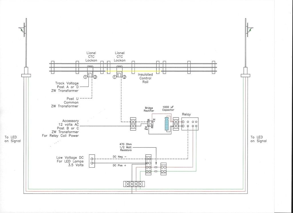
Here is my wiring plan for this block signal set-up.    The actual  length of the control rail is around 8 feet.  Again - I have several signals on my layout - and only this pair of signals is having this problem.  Any Ideas ?  What is the Static electricity doing ?   Me thinks it has something to do with the resistors ??


Steve


Original Post

Replies sorted oldest to newest

Do you have a multimeter?  After the spark, when you say the relay is still working you know this because you hear it "click" on/off albeit only the red works?


If the spark occurs on the track, what's curious is your red/green LED circuit is electrically isolated from the track via the relay.  Assuming the greens on your other blocks are still working in this failure mode, I'd measure the voltage at each point from the relay contact, thru the resistor, and on to the LED.  That ought to isolate the problem.

Stan  - Thanks for your reply.

I have a multimeter and have check various points of contact in the circuit - have checked how many Ohms of resistance on the resistors  - the voltage going to the relay and voltage to the LEDs.   You would think that the problem would effect the other signal circuits seeing as how they are all pretty much wired in the same way.


Steve

Hi,Steve

I would start from scratch. Rewire the how relay again. Sound like a resister problem.

or your led's is miss reading the current across it. Also check the block first in could be giving a fores reading to it because of the spark you talked about too.


Also I have better wiring schedmtic that will work a lot better for you too.


Your schedmitic works. My schedmtic will give you a lot more opition with less problems.

John

kb2agpjohn@aol.com or give me a call 848-992-2157


Originally Posted by stan2004:

So then in the failed condition, what are the measured DC voltages with "+" red meter lead as shown, and "-" black meter lead at points A and B?


ogr block

My Low voltage DC supply is 3.5 Volts.   When the signal fails - The voltage  at "A" past the resistor to the LED shows only 0.3 volts.  When the green signal works the voltage at "A" past the resistor is 2.0 volts.   In both cases, on the red signal the voltage past the resistor is 1.7 volts.   At "B" on your note the voltage is the same as the DC Supply of 3.5 volts.


Steve

Originally Posted by NYC,SUBWAY TRANSIT SIGNAL:

Hi,Steve

I would start from scratch. Rewire the how relay again. Sound like a resister problem.

or your led's is miss reading the current across it. Also check the block first in could be giving a fores reading to it because of the spark you talked about too.


Also I have better wiring schedmtic that will work a lot better for you too.


Your schedmitic works. My schedmtic will give you a lot more opition with less problems.

John

kb2agpjohn@aol.com or give me a call 848-992-2157


I spent the better part of Friday working on this.  I pretty much took apart and put back together my wiring.  I tried different combinations of resistors.  The LED will light up with the straight 3.5 volts but it is too bright and and I dont want to burn out the LED.  With the 470 resistors the brightness of the LED Lamp is about just right.  What I think is strange I have other signal block wired the same way and they have not given any problems.     


Can you post your schematic here to see how you would wire it differently ?


Steve

Last edited by Steve24944

Green operating: "A" = 2.0V across LED.  Current = 3.2 milliamps; calculated by the remaining 1.5V across the 470 ohm (current = 1.5V / 470 ohms).


Red operating: "A" = 1.7V across LED, Current = 3.8 milliamps.


Green failed:  "A" = 0.3V across LED.  Current = 6.8 milliamps.


Green and red voltages and currents for the operating condition seem OK. 


The failed Green is curious- it draws more current than when operating...yet does so with only 0.3V across it.  I can't explain the why but it seems like the spark induces a "latch-up" condition which can be reset.  What's curious is that both Greens fail together - my guess is that one fails and drags down the other so to speak.  To that end, since it appears this is easily repeatable, I'd be curious to see what happens if you remove one or the other Green LED wire, induce the failure in the remaining Green LED, then re-attach the 2nd Green wire.  Obviously you can go wild dreaming up experiments to narrow it down, swapping parts, etc. etc.  As for a remedy, I'd put a small capacitor, one each across each green LED right at the signal head.  If that's inconvenient, try just at the terminal block where both green LEDs are connected.  Something like 0.1 uF (microfarads) or really whatever you have lying around in that ballpark is a good starting point.


Very interesting indeed.

Originally Posted by stan2004:

Green operating: "A" = 2.0V across LED.  Current = 3.2 milliamps; calculated by the remaining 1.5V across the 470 ohm (current = 1.5V / 470 ohms).


Red operating: "A" = 1.7V across LED, Current = 3.8 milliamps.


Green failed:  "A" = 0.3V across LED.  Current = 6.8 milliamps.


Green and red voltages and currents for the operating condition seem OK. 


The failed Green is curious- it draws more current than when operating...yet does so with only 0.3V across it.  I can't explain the why but it seems like the spark induces a "latch-up" condition which can be reset.  What's curious is that both Greens fail together - my guess is that one fails and drags down the other so to speak.  To that end, since it appears this is easily repeatable, I'd be curious to see what happens if you remove one or the other Green LED wire, induce the failure in the remaining Green LED, then re-attach the 2nd Green wire.  Obviously you can go wild dreaming up experiments to narrow it down, swapping parts, etc. etc.  As for a remedy, I'd put a small capacitor, one each across each green LED right at the signal head.  If that's inconvenient, try just at the terminal block where both green LEDs are connected.  Something like 0.1 uF (microfarads) or really whatever you have lying around in that ballpark is a good starting point.


Very interesting indeed.

If only one signal is wired up - and not two - does not change the problem. 


The only capacitors I have laying around in my parts box are 220uF 35 v  If I got a 0.1 uF like you suggest - attach the neg side of the capacitor to the neg wire going to the LEDs at the terminal and the other side to the pos wire going to the LEDs.


Steve

 Power supply for the LEDs is 3 volt but are too bright so you've used a 470 ohm to reduce the current... What would happen if you put the resistor on the - negative side  (ground)of the led going to each signal.  If things have been working for months something has failed, Resistor  led  relay contacts?? Any spare LEDs around you could test with?  Which leds are giving you the problem? The Bi colored with 3 leads?

First the 12 VAC input from the transformer goes to a bridge and capacitor which converts voltage to DC and charges it to peak. That is about 17 volts DC on what I assume is a 12 volt DC coil. The coil can probably take 18 volts but why stress it out?  I would reduce the voltage down to 10 volts AC. Second I would add an 18 ohm half watt resistor in series to one of the capacitor leads. That will slight slow current inrush into the capacitor, reducing wheel arcing on the outside train wheels completing the circuit when the first set of wheels enters the block.


The relay coil should also have a diode across it,the coil can generate a spike,at least on that circuit.


Describe the 3.5 volt power source,is it regulated?  and what else it powers,if anything besides LEDs. It is possible there are harmful voltage spikes on the line, just a thought.


Dale H

Last edited by Dale H

Dale -

The 3.5 DC power source is a small power pack that came with a Bachmann G Scale Big Hauler Set.  This DC power supply is used for 3 other signal set-up on the layout.  I have had this set up in place for 4 or 5 years and have never had problems until this glitch showed up.   And it is only this one signal circuit - the other signals have been working just fine.


Steve

Originally Posted by Steve24944:

Dale -

The 3.5 DC power source is a small power pack that came with a Bachmann G Scale Big Hauler Set.  This DC power supply is used for 3 other signal set-up on the layout.  I have had this set up in place for 4 or 5 years and have never had problems until this glitch showed up.   And it is only this one signal circuit - the other signals have been working just fine.


Steve

Can you test the  faulty signal by connecting it directly to the power supply?  Ground(-dc) and then each lead one at a time to the positive , Why not put the resistor on the ground side, You'd only need 1 instead of 2.  


Originally Posted by Steve24944:
If only one signal is wired up - and not two - does not change the problem. 


The only capacitors I have laying around in my parts box are 220uF 35 v  If I got a 0.1 uF like you suggest - attach the neg side of the capacitor to the neg wire going to the LEDs at the terminal and the other side to the pos wire going to the LEDs.


So if only one is hooked up, it behaves the same.  Did you happen to test both individually (i.e., each of the two on this circuit fails by itself)?


Darn about the caps.  If you don't have some lying around I feel bad suggesting you roll-the-dice on the cap remedy since I see Radio Shack charges $2.49/2 for 0.1uF caps.  Ouch!  http://www.radioshack.com/0-1u...or-pk-2/2720135.html


Heck, if you post a temporary/aliased email address or way to reach you, I'll pony up the 49 cent stamp to send a few 0.01, 0.1, and 1.0 uF caps to try.


In no particular order, here are some thoughts going thru my noisy mind:


1. It's got to be the Green LED acting up since all you have in the circuit is the LED, resistor, and wiring/connectors.  You said you re-checked the wiring.  Did you say you changed the green 470 resistor (or perhaps just swapped it with the red 470)?


2. Per the RS site, your LED has 4-legs suggesting independent red and green LEDs within device.  And it makes sense the green failed since presumably the signal head is Green most of the time.


02760028_01

3. It's amazing that both Green LEDs failed simultaneously and in the same way.  I've never seen this failure mode in an LED...and it's hard to imagine the physics of this kind of failure given the relatively simple internal structure of an LED.


4. Your track circuit and signaling circuit are electrically isolated - via separate transformers on the power side, and via a relay on the signaling/control side.  This suggests the spark might be inducing an electrical upset via a radiated field.  So another idea is to, if practical, twist the wiring to the signal heads.  I looked at a photo of your wiring in a previous thread an it looked like you were using ribbon phone cable so that would be a bother.  The idea is to reduce the size of any loops in the wiring.  Loops act a collectors of fields and convert them to voltage spikes.  So while you diagram shows 3 wires "bundled" together making a small exposed loop, if this is not the case and the common wire goes to the signal head separately, try bring the 3 wires together perhaps even make a few wraps of the common around the red/green wires if possible.


5. Ideally, if you have the caps, they should go right at each signal head since my theory is you need to protect the green LED (between common and the LED input).  A distant 2nd choice is to put a single cap back at the terminal block under the layout where both Greens connect.  Caps of this size (0.1uF) are non-polarized so can be connected either way.  Polarized caps will be plainly marked as such in which case of course you'd hook "+" to the more positive voltage of the circuit.


6. I suppose there's a case to simply swapping out the LED and moving on.  And I suppose with RS closing stores and such, it might be a good idea to get some backup LEDs anyway. But if this was slow degradation on the parts (after years), who needs this happening again down the road or perhaps to some of the other signal heads that just haven't presented yet.  Hence, I think wise to make some attempt to find the root cause.  But I'm also mindful that, No job is easier than the one you imagine someone else doing.


This is really a head-scratcher. 


Attachments

Images (1)
  • 02760028_01

Add Reply

Post

OGR Publishing, Inc., 1310 Eastside Centre Ct, Suite 6, Mountain Home, AR 72653
800-980-OGRR (6477)
www.ogaugerr.com

×
×
×
×
Link copied to your clipboard.
×
×