
stan2004 posted:
mike g. posted:
...Stan if I just use a DPDT switch I would wire the limit switches just as before correct?
I assume you are referring to your earlier thread about where/how to connect limit switches.  Correct, nothing changes from before.  From an electrical/wiring perspective the linear-actuator is just a DC motor as before.
 
dpdt%20bridge%20drive%20with%20limit%20switches


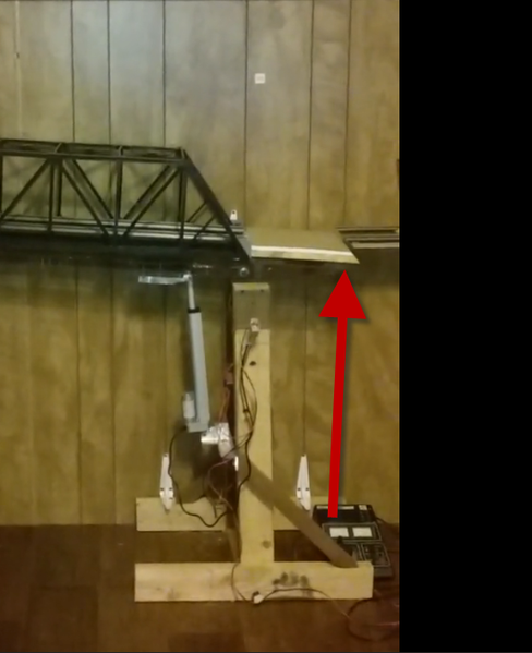
Thanks Stan, when the actuator arrives next week I will post some updated pictures.

Hi Guys and Gals, Here is a little update. I have been working on the bridge and got my Linear-Activator installed. Here is the deal, I need some help to figure out placement of it so it will open to and 90 degree and still   close all the way. here is a video of what I have sofar. Any help would be great!

Attachments

Videos (1)
20161116_120843

The first thing I thought was "why did he put the actuator on that side of the pivot point?"  So even if you could rotate the bridge to full vertical you'd have the actuator sticking out in the aisle which will catch on your belt, shirt, whatever as you walk by.  So I guess my first question is to ask if there's some reason you can't (or don't want to) put the actuator on the right side of the pivot?

I know you forgot to write down the bridge weight, but let's just say it weighs 10 lbs and assume (for the sake of discussion) that this is evenly distributed across the bridge).  From high school physics this is equivalent to a 10 lbs weight sitting about 24" from the pivot point.  So if your actuator can drive 200 lbs, this means you can theoretically raise/lower the bridge by applying the actuator 200/10=20 times closer to the pivot point on the right side of the pivot...or just a few inches away from the pivot. 

Since you "only" have a 10" linear travel, I think you need to use this 20x leverage to allow you to swing the bridge the full 90 degrees (ignoring whether or not real bridges swing to true vertical!).

No, the actuator can be attached to bridge close to the pivot point on the bottom. It has enough power to push it up from there and stay out of aisle.

That looks really slick, Mike!

Mount the actuator base on a cross member attached to the rear outside edge of the stand/base. That will move it back, mostly out of the aisle.

Then fit the height position with the actuator nearly fully extended and the bridge held in a 90° vertical position. Attach the bridge mount near the pivot and the base will mount where it's located/falls. That's where the mounting cross member will need to be.

I think the grandchildren will be playing with the bridge a lot.

Hi all,

Stan the reason I didn't put it on the right side to pull it down is I also made a counter weight for it and was going to mount it there.  But it sounds like you and Carl are thinking the same thing.

Carl, I will try putting the actiuator a few inches from the pivot point and see how it goes. I will take some pictures as I go along and another video when I am done.

Hi All, Thanks for everyone's help I think I have got it almost where I want it. Tomorrow I will adjust the up limit switch, wrap the wiring, and be happy!! I hope you all like it.

Special thanks to Elliot for the limit switches,

Stan for the wire diagram,

Carl for his idea of moving the pivot point.

Gunrunner John for the idea for a counter Balance, wish I could have used the one I poured. But it would hit the actuator.

I am always open for input and ideas!

Attachments

Videos (1)
20161117_170712

Thanks Carl,

I did try it on the back side and between the support legs, but when I raise the bridge the tail end would hit the actuator. The location where it is should be ok, as that part of the bridge support will be behind the wall on one side of the door entering the room. The Bridge is 40" long and my door opening is 32" so that means 8" will be out of the path entering the room.

Not sure, but plumbing supply houses used to sell lead in five pound increments.  I don't see any reason why they wouldn't still have the lead.  Plumbers use the lead to seal pipe joints in cast iron pipe.  For those not familiar with the method, it goes like this.  Basically you have a propane tank, not too different from the barbecue type.  On top of the tank there sits a burner mechanism with it's propane supply hose connected to the tank.  On top of the burner sits a kettle.  The lead ingot was placed in the kettle and heated until it is molten.  Then the plumber dips a ladle into the molten lead and pours it into the pipe joint.  

Bottom line here, Mike, is that the lead ingots are roughly a 3" square cube.  It wouldn't be too difficult to drill holes into it for eye bolts.  Then you could hang it from the bridge.

Avanti posted:
gunrunnerjohn posted:

Maybe you need to find a big chunk of lead for a smaller form factor.

Depleted uranium, maybe? 

Maybe he can get someone to fire a shot from the M1A1 into the train room.  Once the damage is repaired, he has the heavy chunk of material to build the counterweight.

This looks to be about the right size...


Certified Pure Lead Brick (99.9% Pure) 26.2 pounds

Attachments

Images (1)
  • mceclip0
mike g. posted:

Thanks Carl,

I did try it on the back side and between the support legs, but when I raise the bridge the tail end would hit the actuator. The location where it is should be ok, as that part of the bridge support will be behind the wall on one side of the door entering the room. The Bridge is 40" long and my door opening is 32" so that means 8" will be out of the path entering the room.

Sweet! Now you have the power lift bridge setup.

First off I would like to thank everyone for there comments!

Second I would like to thank Mark, Carl, Max, RTR12, Pete, Stan, Dan, and John! Without you guys I would still be in the dark over this darn thing. Also now that it work you all have made my wife happy! Now I can do some of the things she wants done. She is a good woman and lets me do train stuff to a point and I know I spend to much doing it.

Thank You again to you great group of guys!!

Now to think of a new project that doesn't take a lot of money ( Scratch Build)

Add Reply

Post

OGR Publishing, Inc., 1310 Eastside Centre Ct, Suite 6, Mountain Home, AR 72653
800-980-OGRR (6477)
www.ogaugerr.com

×
×
×
×
Link copied to your clipboard.
×
×