Dale H and I were talking about this over on What did you do on your layout today. After a few rounds of back and forth, it became clear the discussion needed its own topic.


Let me start off by saying that this type of computer control is not for the faint of heart, but boy, is it powerful stuff. The main reason that I'm using it on my railroad, instead of some of the newer technologies, is that I already own the equipment.


So what is CMR/I? In the most basic terms, it is a hardware system consisting of a bunch of on/off switches connected to a computer by a serial line. The switches come in two "flavors", inputs and outputs. What you can control with them is really only limited by your imagination. For my railroad, I'll be using inputs for detection, to tell the computer where the trains are, and outputs for throwing turnouts and running prototypical signaling. Let's take a look at some of the components that I'll be using. Keep in mind these are more than 20 years old.


Let's start with this gizmo. This converts the RS-232 serial protocol from the computer to RS-422 for use out in the field. My understanding is that it needs to be converted in order to travel the distances needed around the layout. There are newer protocols that can do more, but again this was what was available back when I started.


IMG_6008

This is a motherboard. The next three boards plug onto it.


IMG_6009

This is a USIC, which stands for Universal Serial Interface Card. This is the brain of each mother board. It packs and unpacks the data for transmission over the serial line. The line connects to the pins on the top, and the bottom plugs into the first space on the motherboard.


IMG_6010

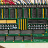
This is an input card. It has 24 individual input switches. It plugs onto the motherboard on the bottom, and the inputs from the layout connect to the pins at the top. It reads conditions on the layout, and sends that information back to the computer for calculations, through the above chain of devices.


IMG_6011

And, this is an output card. Essentially the same as the input, but with the opposite information flow. It is the workhorse of the system, turning things on and off.


IMG_6012

So there you have it, CMR/I theory in a nutshell. Unfortunately, I'm not an electrical engineer, so I know nothing about all those chips. If I was given a blank card and a bag full of components, I could assemble one. I just couldn't tell you why it works on an internal level.


But enough background. I welcome all discussion on this subject from anyone interested, and I'm always interested in learning more if anyone out there has experience with this system.


I'm going to continue my conversation with Dale, but everyone should feel free to jump in with comments or questions and I'll do my best to respond.


Originally Posted by Dale H:
Originally Posted by Big_Boy_4005:
Originally Posted by Dale H:
Originally Posted by Big_Boy_4005:

Dale, I use GarGraves track, so all my rails are insulated. The second outside rail will be connected to CMR/I input bits and go back to the computer. That information will be processed by JMRI Panel Pro and show up on a video dispatch display with a full schematic of the mainlines, including all the appropriate signaling.


CMR/I stands for Computer Model Railroad Interface. This is a hardware system consisting of input and output bits that is connected to a computer by a serial line. For smaller railroads, Arduino or Raspberry Pi processors could probably do the same functions. Once again, I just happen to own all the CMR/I equipment, more recycling.


JMRI stands for Java Model Railroad Interface. It is free software, CLICK HERE to learn more.

Elliot


I take it that the computer sends out a small voltage and measures resistance or amps? Either 0 or 1 to detect occupancy? Meters I worked on generally use 5 to 15 ma and measure quantity. Thanks for the reply.


Dale H

Not exactly Dale, a DC ground is superimposed over the AC common. That ground signal does the classic wheel / axle jump to close the circuit. The other side is 5 VDC back at the input card which is seeking the ground source to drive the bit high. There are also some capacitors and a diode that filter and direct that track ground before it reaches the card. I'll take some pictures and show you what I have. It might help.

thank you Elliot.


I would like to know how it works, electronics is a hobby of mine.


Dale H

OK Dale, there are the photos, and a pretty good overview of the system.


The next few pictures are of what I call detection panels. What you are looking at is just a tiny corner of one of them. I have 4 of these panels, each is 2' x 4' and has a lot of these individual units on it. I think the layout calls for something like 225, so I may only need 2 and a partial to do the job. Unfortunately, I liquidated a bunch of the input cards years ago, and now I might be a couple short.


These panels were assembled by an electrical engineer for my layout at Mall of America back in the early 90's. He figured all this stuff out. Back then, we ran the trains on DC. I hope my lack of electronic savvy hasn't foiled my plans here. He did leave us a few clues, that's his handwriting in the faded ink.


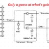
The 2 terminals with the 12 gauge jumpers going between them, are ground. The one in the middle comes from the track, and the one on the right goes out to the CMR/I input card. The one on the left, behind the huge diode says "scoreboard". That was our nickname for an LED display panel that would show the public where the trains were. No need for that on this layout, no public, and I have something far better in mind. That's part of that JMRI thing. We can expand the conversation to that later.


IMG_6013

I took these last two in the hopes of seeing the values on those capacitors. I'll go down there with a flashlight and my glasses if it becomes important. I think they're 1000uF.


IMG_6014

IMG_6015


I was hoping you or someone else here might be able to shed some light on what the "track" input voltage might be, and even more importantly if it can be taken directly from the track, now that I have gone back to AC power.


Original Post

Replies sorted oldest to newest

Originally Posted by Big_Boy_4005:

Dale H and I were talking about this over on What did you do on your layout today. After a few rounds of back and forth, it became clear the discussion needed its own topic.


Let me start off by saying that this type of computer control is not for the faint of heart, but boy, is it powerful stuff. The main reason that I'm using it on my railroad, instead of some of the newer technologies, is that I already own the equipment.


So what is CMR/I? ... Let's take a look at some of the components that I'll be using. Keep in mind these are more than 20 years old.


...

Elliot, thanks for starting this thread, as it's definitely a topic worthy of it own thread.  I avoid that super-thread, because it's so large now... and impossible to follow.  


Anyway, I too would be very interested in how this technology can be applied in today's 3-rail world.  I first heard of CMR/I back in my teen HO years... (i.e., 40+ years ago in the mid-1970's) when Model Railroader magazine first covered the topic on Bruce Chubb's Sunset Valley HO empire.


Like yourself, I'm not an EE... So I only understand the general concepts involved but not the electrical/hardware theory behind all the components.  But I'll jump in to contribute whenever possible. Hard to believe nearly 40 years have passed, since I first read about CMR/I.  Where did the time go?


BTW, as an FYI... your images are all appearing as "image not found" boxes when I view your original post.  So you might want to look into that.  I'd be interested in seeing them.


Will definitely stay tuned...


David

Last edited by Rocky Mountaineer

Sorry about the pictures guys. For some reason, I can see them perfectly, and they were there when I wrote the captions. I don't start a lot of topics, and the form looks different from a regular post. I tried to edit the post, but without getting Rich involved, I'm not sure how to fix it. See if this works. I'm pretty sure I can repair this if it doesn't. I really want you to see them so we can get this conversation off on the right foot.


Let's start with this gizmo. This converts the RS-232 serial protocol from the computer to RS-422 for use out in the field. My understanding is that it needs to be converted in order to travel the distances needed around the layout. There are newer protocols that can do more, but again this was what was available back when I started.


IMG_6008

This is a motherboard. The next three boards plug onto it.


IMG_6009

This is a USIC, which stands for Universal Serial Interface Card. This is the brain of each mother board. It packs and unpacks the data for transmission over the serial line. The line connects to the pins on the top, and the bottom plugs into the first space on the motherboard.


IMG_6010

This is an input card. It has 24 individual input switches. It plugs onto the motherboard on the bottom, and the inputs from the layout connect to the pins at the top. It reads conditions on the layout, and sends that information back to the computer for calculations, through the above chain of devices.


IMG_6011

And, this is an output card. Essentially the same as the input, but with the opposite information flow. It is the workhorse of the system, turning things on and off.


IMG_6012

So there you have it, CMR/I theory in a nutshell. Unfortunately, I'm not an electrical engineer, so I know nothing about all those chips. If I was given a blank card and a bag full of components, I could assemble one. I just couldn't tell you why it works on an internal level.


But enough background. I welcome all discussion on this subject from anyone interested, and I'm always interested in learning more if anyone out there has experience with this system.


I'm going to continue my conversation with Dale, but everyone should feel free to jump in with comments or questions and I'll do my best to respond.


Originally Posted by Dale H:
Originally Posted by Big_Boy_4005:
Originally Posted by Dale H:
Originally Posted by Big_Boy_4005:

Dale, I use GarGraves track, so all my rails are insulated. The second outside rail will be connected to CMR/I input bits and go back to the computer. That information will be processed by JMRI Panel Pro and show up on a video dispatch display with a full schematic of the mainlines, including all the appropriate signaling.


CMR/I stands for Computer Model Railroad Interface. This is a hardware system consisting of input and output bits that is connected to a computer by a serial line. For smaller railroads, Arduino or Raspberry Pi processors could probably do the same functions. Once again, I just happen to own all the CMR/I equipment, more recycling.


JMRI stands for Java Model Railroad Interface. It is free software, CLICK HERE to learn more.

Elliot


I take it that the computer sends out a small voltage and measures resistance or amps? Either 0 or 1 to detect occupancy? Meters I worked on generally use 5 to 15 ma and measure quantity. Thanks for the reply.


Dale H

Not exactly Dale, a DC ground is superimposed over the AC common. That ground signal does the classic wheel / axle jump to close the circuit. The other side is 5 VDC back at the input card which is seeking the ground source to drive the bit high. There are also some capacitors and a diode that filter and direct that track ground before it reaches the card. I'll take some pictures and show you what I have. It might help.

thank you Elliot.


I would like to know how it works, electronics is a hobby of mine.


Dale H

OK Dale, there are the photos, and a pretty good overview of the system.


The next few pictures are of what I call detection panels. What you are looking at is just a tiny corner of one of them. I have 4 of these panels, each is 2' x 4' and has a lot of these individual units on it. I think the layout calls for something like 225, so I may only need 2 and a partial to do the job. Unfortunately, I liquidated a bunch of the input cards years ago, and now I might be a couple short.


These panels were assembled by an electrical engineer for my layout at Mall of America back in the early 90's. He figured all this stuff out. Back then, we ran the trains on DC. I hope my lack of electronic savvy hasn't foiled my plans here. He did leave us a few clues, that's his handwriting in the faded ink.


The 2 terminals with the 12 gauge jumpers going between them, are ground. The one in the middle comes from the track, and the one on the right goes out to the CMR/I input card. The one on the left, behind the huge diode says "scoreboard". That was our nickname for an LED display panel that would show the public where the trains were. No need for that on this layout, no public, and I have something far better in mind. That's part of that JMRI thing. We can expand the conversation to that later.


IMG_6013


IMG_6014

IMG_6015

I was hoping you or someone else here might be able to shed some light on what the "track" input voltage might be, and even more importantly if it can be taken directly from the track, now that I have gone back to AC power.


Attachments

Images (8)
  • IMG_6008
  • IMG_6009
  • IMG_6010
  • IMG_6011
  • IMG_6012
  • IMG_6013
  • IMG_6014
  • IMG_6015
Last edited by Big_Boy_4005

Glad you guys can see them now. I may still ask Rich to clean up the mess by repairing the images and perhaps editing your posts to take out the "can't see" bits.


David, the CMR/I series of articles ran in MR in 1985 and 86. I would have to look back to see if there were any earlier published references. I'm sure he was developing the system years before. That said, I purchased my equipment in 1992, but there were probably only minor changes to the hardware from when the series ran. So at best, I'm working with late 70's or early 80's technology. Most of what I'm using is still available, though there have been major new product advancements.


If you Google CMRI, it is difficult to find what you want. But if you Google JLC Enterprises, it comes right up. If I'm not mistaken, JLC is his wife's initials. Family business since day one.

Originally Posted by Big_Boy_4005:

...


David, the CMR/I series of articles ran in MR in 1985 and 86. I would have to look back to see if there were any earlier published references. I'm sure he was developing the system years before. That said, I purchased my equipment in 1992, but there were probably only minor changes to the hardware from when the series ran. So at best, I'm working with late 70's or early 80's technology. Most of what I'm using is still available, though there have been major new product advancements.


...

MR had been featuring lots of articles on Bruce Chubb's Sunset Valley RR in the 70's (maybe even earlier), but PC technology hit the early mainstream about 1983-ish with the IBM XT.  I recall purchasing a second 10MB "hard-drive on a card" for it... yes, a whopping 10MB!!!    I think my first PC was configured with 128K of main memory too.  And those numbers are not a misprint.  


So if you have the CMR/I articles in Model Railroader from 1985-86, that's a few years after PC's were just starting to hit households... but not nearly to the extent they did in the 1990's.  And now, of course, we're all walking around with portable PC power and smartphones.  Who would have thunk it back then??? 


David

Originally Posted by Big_Boy_4005:
The one in the middle comes from the track

By "track" do you mean it comes from the isolated-rail section that detects occupancy by shorted axle?


If so, then it's consistent with what you've described so far.  That is, the detector "grounds" the CMRI input pin.  The CMRI input pin drives the input of a digital logic gate (74LS04).  The gate input is pulled up to +5V by a resistor.


From what I can tell from your photos, the cap and smaller diode are as annotated below.  Can you read the marking/lettering on the big diode?  


IMG_6013

Attachments

Images (1)
  • IMG_6013

Now that you mention that David, I do recall seeing a bunch of articles on Chubb's layout long before the CMR/I series. I have every MR from 1950 to 2006 on my bookshelves, I'll have to take a trip down memory lane. Lord knows mine isn't as sharp as it once was, spiders have taken up housekeeping.


I remember those early PC days too. My first one got stolen in about 1984, and I moved up to an XT. I also remember the 10MB extra drive LOL! Today, a single photo can be larger than that.


When I was in college, my major was computer science and geography. Back then it was all about efficiency, the saving of time and space, because those things were limited and expensive. I get the feeling that software companies don't care about those things anymore. If you buy their stuff and it runs too slowly, they expect you to buy a new computer. Heck, the kids who write software these days weren't even born in the pre Pentium era.

Stan, the only markings on those big diodes say DII 6A2. Hope that tells us what we need to know.


This entire project is going to take a long time to become fully operational. It has to happen in stages. It was this image of one of my turnout relay panels that gave rise to this topic.


I'm using these relays to simply flip the polarity going to the Tortoises. Once they are connected to the panel via the terminals on the right, it is just a matter of completing the circuit by applying power to the terminal at the bottom. In phase one, this will be done using temporary control panels with SPST micro switches. Phase two is when CMR/I kicks in. The panels will be removed and the control wires will be connected to the output cards.


IMG_6003


Before the panels can be removed, I also have to set up JMRI Panel Pro and assign the CMR/I bits to the turnouts in the schematic.


Once that is up and running I can move to the detection portion. After that signaling.


So far, everything is fairly academic. Others have done these things before.


There's one thing left to tell you about, and it may sound a little "pie in the sky". I'm going to save that for a little later.


Attachments

Images (1)
  • IMG_6003

Here's my guess at what you have. When an axle enters the detection track section, it shorts the screw-terminal labeled "track" to the Common of the DC power supply.  I believe the 6A2 is simply for protection (as opposed to part of the signal detection circuit). 


4005

The shorted "track" signal then discharges the 1000uF capacitor via the 1N4005 diode.  The cap is normally charged to 5V via the 4.7K resistor.  The 74LS04 digital logic chip senses the level of the capacitor and sends digital signal onward to the computer controller.  Somewhere you have a separate and isolated 5V DC supply to power the digital/computer components.  The common of the DC supply is tied to the outer rail to allow isolated-rail detection.


Using this method, your track transformer voltage can be AC or DC, conventional or command voltage levels.  I did not study the other (long) thread so hopefully this isn't just repeating ideas that have already been discussed.


Attachments

Images (1)
  • 4005

Impressive Elliot, even if it is 1980's or early technology. To me a non-techie it might as will be out of the Space Shuttle ! I remember reading about Bruce Chubb and his computer articles, I'm your age so it's memory lane. Yep, My old sinclair and TRS "trash" 80. Did you use this computer control system for layout control, was your previous layout at the mall of America back in the day? Great thread.

Stan, love the diagram! I believe you've nailed it.


I think I remember being told that that 6A diode was there to prevent track power from getting to the electronics. This detection method is one of the things that makes 3 rail so neat, especially when you use track with all rails insulated.


Prior to the layout at the mall, the same EE designed a timer circuit for use with my portable layout. That layout used tubular track with classic insulated sections. The circuit was connected to the relay and had 3 inputs. One 24VDC + one 24VDC - and the third came from the insulated rail segment. Once again we superimposed that DC ground on the AC track common. Train hits the section, relay latches, and a trim pot sets the rate of discharge of a capacitor. Voila, timer!


I'll see if I can find the schematic and the parts list and share it.

Originally Posted by Seacoast:

Impressive Elliot, even if it is 1980's or early technology. To me a non-techie it might as will be out of the Space Shuttle ! I remember reading about Bruce Chubb and his computer articles, I'm your age so it's memory lane. Yep, My old sinclair and TRS "trash" 80. Did you use this computer control system for layout control, was your previous layout at the mall of America back in the day? Great thread.

Thanks George. That was the plan, to use it on the mall layout. The hardware was all set and ready to go. The snag was the software all had to be custom done. Shortly after we opened, it was clear that we couldn't afford to keep throwing money at it, and we started bypassing the CMR/I elements, in favor of relay and micro processor solutions.


Fast forward 10 years. When I started thinking about what I was going to do for control systems on this layout, I knew I wanted to reuse the CMRI stuff. I had just discovered TMCC, and that serial port on the back of the command base. I thought wouldn't it be cool to combine the two and go for full automation. I nicknamed this concept "smart track and smart trains". CMR/I would take of the smart track, with detection signaling and routing.


Once again, it was the software that was giving me trouble. I was starting to think that I was going to have to write it myself. I even bought a book on C++. Then one day I heard about JMRI. I looked into it and realized that this was the MISSING LINK!!! Lo and behold, already written into the system, were the TMCC command codes.


Not only can JMRI talk to the command base, but it is pretty much plug n play with CMR/I. Just build your layout schematic with Panel Pro, then assign your bits for detection, turnouts and signals.


There is little doubt in my mind that I will have to learn Java, and write some modules myself, but a lot of the hard part is already done. Best of all, it's free!

Originally Posted by Professor Chaos:

You don't need to learn any Java to use JMRI.... besides the off-the-shelf signaling logic, you can create almost any behavior by defining 'logix' within PanelPro.


For really complex stuff you can add custom scripts written in Python.  I've written a few but not really understood what I've been doing.

I'm glad to see you here Prof. I really haven't examined the finer detail of what is available "off the rack" with JMRI.


Here's an example of what I would like to start with in terms of automation. I have a very large storage / staging yard. It consists of five 120' long tracks. I've divided each track into 5 stopping areas, so the yard can hold a max of 25 trains. When the first train in a queue leaves the yard, the subsequent trains need to advance to the next position.


Can JMRI do that? Please say yes!

Hi Elliott -


I think the answer is yes, but that's much more complicated than anything I have attempted with JMRI.  I use JMRI mostly as a control panel to control turnouts, accessories, and operating cars; an Arduino runs the trains but is limited to an ABS-like system That I developed.


But (if you haven't already) take a look at the Warrants section of the JMRI website - that's where they describe the automation capabilities.  But it's so complex it makes my head spin!

Prof, thanks for pointing me in that direction. I'll check it out. There is no rush with any of this, because the hardware probably won't be done enough for at least 8 to 10 months maybe more. I have a lot of work to do on the layout itself, I don't even have the track fully powered. And then there's Panel Pro.


Dale, you're welcome. Yes this is old technology, but the cards are mass produced and sold loose or in kit form or you can have them assembled for an extra charge. The thing that's homemade is the detection panel. Take your time and check it out when you're fresh. This topic isn't going anywhere.

I actually use the C/MRI protocol to communicate between the Arduino and JMRI;  the Arduino emulates C/MRI nodes in software to keep JMRI apprised of layout status, and let JMRI control layout items.  I even use this protocol to have JMRI pass TMCC commands to the Arduino, which then passes them on to the Command Base.


So if you wanted, you needn't be confined to actual C/MRI hardware. You could connect any kind of I/O hardware you wanted to the Arduino, and make it look like C/MRI hardware to JMRI.


This book by Bruce Chubb describes the C/MRI hardware and protocol in detail, though I think there are newer boards not covered in the book.


Thanks Prof, that sounds pretty cool.


I've got the book, autographed too. Got all the hardware as well, except an input card or two as mentioned earlier. Our paths have crossed a few times here in the forum, but you may not be familiar with the magnitude of my layout. It's quite the undertaking really.


Here are some vital statistics:

  • The room is ~1900 sqft
  • The layout is ~2200 sqft because it is full double and part triple deck
  • There is over 3000' of track
  • The mainlines are about 6 scale miles long
  • There are over 300 switches
  • There are 124 powered by Tortoises with 20 being crossovers
  • There are 74 power districts
  • Over 200 detection blocks
  • It is powered by six 20 Amp power supplies
  • It has 32 train staging capacity
  • There are two helixes a 10' diameter and an 8' diameter

If you'd like to see what it looks like just click on the links in my signature.


BTW, I just downloaded JMRI to this computer. Now I have to figure out how to use  the layout editor. I still need to check out the section you mentioned earlier. Long day, but a good one.


Last edited by Big_Boy_4005

Glad you started a new thread. It's a good subject and something I am interested in as well, but not very knowledgeable about. One of the problems I have is the fact that all the C/MRI and JMRI equipment and information is for DC/DCC and I have all AC with Legacy & DCS. The interfacing between DC and AC with the equipment seems a bit confusing to me. I will follow along and study the websites some more, maybe some of it will stick.

Originally Posted by rtr12:

Glad you started a new thread. It's a good subject and something I am interested in as well, but not very knowledgeable about. One of the problems I have is the fact that all the C/MRI and JMRI equipment and information is for DC/DCC and I have all AC with Legacy & DCS. The interfacing between DC and AC with the equipment seems a bit confusing to me. I will follow along and study the websites some more, maybe some of it will stick.

Actually, the command codes for TMCC and now Legacy are in JMRI. Sorry, no DCS, talk to Mike about that. It is one of the reasons I don't do MTH engines.


What you use for track power doesn't really enter into the picture. The only place that I can think of where you would come into contact with track power is detection, and that doesn't really happen, but that big diode is there just in case.


Study the diagram above that Stan drew. That's what the detection panels are for. They serve as a buffer and an interface between C/MRI and the track. The way I'll be doing it, a DC ground signal will go out on the outside rail along with the AC common and the TMCC signal. The passing train allows that DC ground to get back to the detection panel, and then back to the C/MRI input bit. From there, it goes back to the computer and is processed by JMRI.


If you wanted to, I suppose you could also control accessories with C/MRI and JMRI as Professor Chaos suggested, however for that, you would probably need a relay. You would have a C/MRI output bit drive the relay and allow AC or DC any voltage to pass. You can find banks of up to 8 relays mounted on a card for cheap on eBay. I think they have 5VDC coils and are perfect for these applications.


Hope that helps.

Last edited by Big_Boy_4005

Train detection was mostly what I was talking about. I looked at the CMRI site and their detection modules are either DC or DCC. I have relays (AC and DC) and also some of the relay banks from ebay. I have been fiddling with an Arduino and photo resistors, but maybe I will try your method and see what happens. I think stan2004 also told me something about DC mixing with the AC on the rails one time, may be the same method you are using here that he was talking about. I suppose that would be isolated rail, only with DC. I really don't have a layout large enough to justify all this, but I still find it fun to fiddle with...and I do hope to expand someday. 


Without going into C/MRI, you may be able to accomplish the superimposed DC ground method with Arduino. You'll probably still want to use the diodes and capacitor between the track and the input of whatever system you use. I'm not 100% sure, but I think the purpose of the capacitor is to smooth out the signal so the input doesn't see a "flicker". Even if your wheels and track are clean there can be momentary signal loss.


I'm sure Stan or one of the other electronics experts could confirm or deny my theory.

Last edited by Big_Boy_4005

Here is a circuit I use to generate a clean logic signal from a standard AC third-rail sensor.  It uses an AC optocoupler, a long RC filter, then feeds the signal into a Schmitt trigger:


sensor


I built a circuit board that has 24 of these sensors, then collects all the signals with shift registers so you can read all 24 sensors with 3 wires from an Arduino over an SPI bus:


acsensor

ACsensor board in place

Attachments

Images (3)
  • sensor
  • acsensor
  • ACsensor board in place
Last edited by Professor Chaos

Add Reply

Post

OGR Publishing, Inc., 1310 Eastside Centre Ct, Suite 6, Mountain Home, AR 72653
800-980-OGRR (6477)
www.ogaugerr.com

×
×
×
×
Link copied to your clipboard.
×
×