
In 2013 I posted a detailed description of the rebuilding my Pennsylvania & Pacific RR. This over 10 year saga covers all the details of building this railroad since that time. You can go back to the beginning with constructing the L-girder platform, laying over 300 feet of Ross track, building and wiring the control panel at this location on the Track Planning and Layout Design Forum.

https://ogrforum.ogaugerr.com/...-vs-old-build-thread

This railroad is on its third life. It was first constructed in Germany and was 21 X 13. It was built with the goal of disassembling and shipping back to the USA to our house in Bucks County, PA. I put it back together with an added 6 ft in length so it became 27 X 13 ft. After my early retirement from the housing industry in 2009, and our subsequent move to Louisville, KY, I modified it, and rebuilt it as a much larger, 39 X 15 ft railroad. I worked to eliminate all of the operational problems I had in the first two versions. The railroad is star-wired with 38 separately controlled blocks. It does not have digital control yet, but I wired it using home-run wiring throughout with high-capacity twisted pair wiring so it can get DCS whenever I'm ready to buy it. Meanwhile, it is a "Cab-control" layout run from both sides of a single-Z-4000 transformer. It has a separate DC power supply running the LED indicators for the block toggles and an interlock circuit that protects a swing-out door that permits access to the entire inside of the layout. In fact there are many DC power supplies running all the lighting. I'm using 100% LEDs now and find all of the old AC adapters laying around are a good source of DC power. I just bought my first purpose-built LED power supply to run all the lights in the new engine house. The age of the railroad, from its inception in Germany in 1999, speaks to the longevity of modern O'gauge equipment including 16 locomotives (MTH, Sunset 3rd Rail and one Atlas), Ross Custom Switches with Z-stuff for Trains machines, and the hefty MTH Z-4000 transformer, the newest of which is from 2002.

I noted when starting this thread that the layout was going to be fully scenicked, and it will be a big job that would stretch over years. Boy was I right! I've now been steadily working on it for over 10 years and have had some wonderful sub-projects that are defined in detail in this massive on-going thread. I had hoped that my eyes, hands and back would make it that far, and so far, with a couple of physical challenges creeping in, I'm hanging in there. Whatever you use most wears out first, and since I've been building models since I was 8, the hands are experiencing the most wear and tear. I am grateful for having most of the under-the-platform work finished since the back hasn't been happy either. When I built the layout the first time I was 24 years younger. My wife actually asked me if I was physically capable of the rebuild. I'm happy to report that I am and most of the injuries are temporary... I hope. At the time of this edit, I'm 78, and happily, I'm still building and still learning.

The layout has a large mountain with tunnels on one end and a the small town of Woodbourne on the other. In between are industries, yards and an engine service facility. I really don't have the room so there's no roundhouse or turntable, but there is a large engine house. The middle is open giving me complete access to almost all trackage without resorting to pop-ups (and more work under the table).

Here was my early rendition of the mountain region.

New Mountain Detail

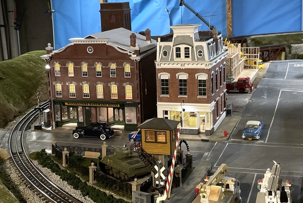
Here's a picture of the layout as it in Dec 2023. Included are the new engine house in the far background all illuminated with LED fixtures, the Hopper House, Heritage Park, the Bourbon rick house under construction and the Woodbourne Hardware House.

P&PRR Status 2023 5P&PRR 2023-5P&PRR 2023-6

The bridges in the foreground-left are customized Plastruct Deck Truss Bridges and the third is a Deck Plate Bridge and they too, and all the beautiful ravine scenery is described here.

Lastly, throughout this massive undertaking there have been some signature projects that have found their way to the model railroad press with a substation described in the November 2015 Railroad Model Craftsman magazine, and a three-part article in the 2018 October, November and December issues of Railroad Model Craftsman on the design and building of a Victorian Bourbon Distillery that existed in Louisville, KY until Prohibition when it was razed. More buildings and articles are coming out of this very comprehensive thread. The Engine House is slated for publication and several articles have been submitted to OGRR.

So, if you're so inclined and have a couple of years to read about the trials and tribulations of big railroad building, please come along for the ride. I don't have all the answers. In fact, I have very few answers, so I expect my readers to be willing to give. And give you do. I get as much from my readers as I give, and many ideas, thoughts and plans came from them. I can point to many critical things that wouldn't have happened if it weren't for all the patient and attentive folks that read and commented on this forum. The articles wouldn't have happened. In fact, the buildings themselves may not have turned out as they did were it not for the support I constantly receive. Some folks that have been following this thread for years give me more credit than I deserve. You become a master of things by doing them a lot and practice. You have to start somewhere. The thought of starting is always worse than the actual journey.

I am now fully engulfed in the world of 3D resin printing with the advent of the newest LCD Mask machines that have dropped the price on these amazing machines so normal modelers can have them in their shop. I've had some 3D printed parts done commercially, but now my capabilities have been greatly enhanced. I'm describing all the trials and tribulations going up this learning curve of a very new technology. A recent project is my rendition of Edward Hopper's "House by the RR" that has many, many 3D printed parts from my design.

The Hopper Original

House by the Railroad

The Hopper rendition "House by the Railroad" as complete, installed on the layout and the lights are on.

House Final Frt Rt

Hopper necessitated relocating the Idaho Hotel which required a new base and parking lot. Since then, I sold the Idaho Hotel to Mark Boyce where he's given it a nice home on his growing layout. I needed urban space for more of my custom projects. Then comes Heritage Park to fill the last oddly-shaped open lot on the layout. Heritage Park features 3D printed columns, lanterns, signs and entry arch. This starts on page 92.

Heritage Park Comp 3Heritage Park Comp 7

And the railroad is undergoing a municipal improvement project with new street lighting and signage as seen in this night photo.

IP12Pro Night Test 4

One last bit of downtown real estate is being filled with a bourbon warehouse (rick house) as it appears under construction. I chose to show it this way since, when finished, they're just a box with a bunch of windows in it. Under-construction is a whole different animal. You can view this build thread starting on page 95.

Screen Shot 2021-04-12 at 10.22.55 AM

The Rick House is done and on the layout.

RH Ground Cover Fin 1

The next up is a model of the extant hardware store in Newtown, Bucks County, PA. Built in 1869, it's been a continuously operating hardware store since. In 1899 it burned down, but was rebuilt in almost original shape. Sometime in that period the owners bought the right side store and combined them into a larger hardware store. I'm doing it with some interior. The upstairs are apartments so I will not model them. All I did was compress the length a bit to fit in my layout space. This it the SketchUp drawing used to both create 3D models for the architectural details which I 3D printed, and the flat design drawings used to laser cut the flat parts. Construction has started and can be found on page 103.

mceclip0

The O'scale Hardware Store is in place, but there's still interior work to be done. None of my buildings are permanently attached to the layout. They're all on bases that are removable to facilitate repair, updates, or if required, sold.

Took a small side trip. With the success of the Hardware Store, the owner of the real store in Newtown, PA commissioned me to make an n-gauge layout to be used as a holiday store window display. I built such a RR with my grandkids when they were MUCH younger and commandeered it to be used to fulfill this job. I was able 3D print an n-scale version of the Hardware House and three other actual replicas of Newtown, PA buildings. It took some work to get the track into shape so it would run unattended, and I'm in process of finishing it up. Story starts on Page 107. The n-scale version looks just like it big brother...

NHH160 Lights On 4

So So sit back, grab a cuppa Jo, and start reading. The Saga begins with ballasting 350 feet of track...

Attachments

Images (14)
  • New Mountain Detail
  • mceclip0
  • mceclip0
  • House by the Railroad
  • House Final Frt Rt
  • Heritage Park Comp 3
  • Heritage Park Comp 7
  • IP12Pro Night Test 4
  • Screen Shot 2021-04-12 at 10.22.55 AM
  • RH Ground Cover Fin 1
  • NHH160 Lights On 4
  • P&PRR Status 2023 5
  • P&PRR 2023-5
  • P&PRR 2023-6
Last edited by Trainman2001
Original Post

Replies sorted oldest to newest

I appreciate comments like that. I'd probably write this day-by-day history even if no one was reading it, but when people tell me it's making a difference for them, that really works for me!


Today I started rail painting. I have buildings to build, but nothing can happen until ballasting is done, and that can't happen until the rails are painted. I have a chunk of track where I experimented with the ballast, so I used it to test the painting. I'm using rail brown from Joe's Model Trains. I bought the paint and one of his rollers at  York a number of years ago. The roller was too skinny to handle O'gauge rails. Now I see on his website that he has a much wider roller to paint O'gauge. I first tried brush painting, but it was not successful. I then tried the air brush and the results were passable. I wiped the rails off when the paint was wet. Here's what it looked like. Pretty realistic looking rail...


Rail Paint Test 2

Rail Paint Test 1


One of the things I like about Ross rail is that it ends at the ties. Gargraves on the other hand, extends below the tie level and you can often see shiny tin plate showing. With Ross, that doesn't happen.


So with this good result, I went at the railroad, realizing that once I started, I would have to paint the WHOLE THING. Some of the track work will be in tunnels so I will mark off those areas and not waste the paint. As it is, I emptied a 2 oz. bottle after painting about 1/8 of the railroad (or less). With the exclusion of the tunnel tracks. I just ordered another 5 bottles of paint on line so rail painting will be stopped until the new paint arrives.


This is one of switches I painted and shows the place I stopped. I think the switches look terrific with the brown rails. 

Rail Paint 4


 Here's a bunch of track painted. To me, it immediately looks like RR track with the polished running surface and the dark rails.

Rail Paint 1


Here's the other end of the painted/unpainted line. That unpainted track will be in tunnel under the city so I'm glad I didn't start painting in that direction.

Rail Paint 2


The airbrush worked well unless it didn't. It was plugging a lot and I spent a lot of time cleaning and recleaning it. I cut the paint with isopropyl alcohol at 2:1, paint to thinner. I don't know if that's the best thinner to use. I also have some Vallejo acrylic diluting agent that I could use. When it worked, it went very fast. When it didn't... well... it didn't. In most cases, it took two or more passes to properly cover the steel. When I first started, I was wiping the rails down with alcohol. After a while I realized this didn't make much of difference and just painted the rails.


Just wait until the ballast goes down...


For the yard tracks, I'm gong to fill in the areas between the tracks with inverted roadbed beveled on both sides. Yard tracks don't have nicely shaped ballast fields. Their tracks are buried in the dirt to the ties or higher. It also reduces the amount of ballast I'll need for that track and there's a lot of it.


It goes without saying I'm not building a Proto:48 railroad, but I am trying to make it as realistic as possible given that I'm using 3-rail track with a fairly high profile with ties that are not really scale-sized and are spiked with staples not spikes and without spike plates. It's a shame that Ross can't paint the track before they ship it. Even if it were an extra cost, it would be worth it since this is a pretty big job. As I'm constantly being reminded, over 300 feet of track makes every task a BIG JOB.

Attachments

Images (6)
  • Rail Paint Test 2
  • Rail Paint Test 1
  • Rail Paint 4
  • Rail Paint 2
  • Rail Paint 1
  • Rail Paint 2

Trainman 2001....

glad to hear you can run trains at last so how about a video of a train going across that roll out area?

I have really enjoyed reading how the new layout came from a thought onto a computer and into the real world.

I retired almost a year ago and am now starting to work on our layout.

the rail brown tweaked my interest so today am going to get some and have a go at it myself so thanks for the insight to a possible color to use as railroad trackage is really a hard one to capture correctly.


hope to read more and please don't be a stranger as I enjoy reading what you have accomplished keep up the good work and I'll bet the grandsons will be staying over more now that summer is around the bend plus grampa has trains running enjoy both.


$oo

The other videos I did were on an iPhone. I don't like them so I'm going to use a more formal method for the next series. I'm going to use my daughter's camera. I now have four complete trains on the rails. Two can run at a time with the others parked in passing sidings.


Here's a picture I took of Norfolk-Southern's track running through Louisville. It is a highly used main line, and the rail is clearly brown. It's not an orange rusty color. The darker the rail the better I like it. This picture was shot in bright sunlight directly on it.


Real Raill Color


Also note that this color extends to the ballast below the rail/ The ballast is a mixture of white and bunch of grays. I'm going with straight gray, but will selectively stain some of it darker for more variety.

Attachments

Images (1)
  • Real Raill Color

Trainman 2001....

I don't remember who posted a thread here but it dealt with creating a two toned ballast effect and if I remember correctly he used black spray paint on grey ballast so it was a gray and a mixture of light and darker black.


you could do same using a brown spray paint and accomplish two items at same time.

all he did I believe is hold spray can 12" above ballast and misted it slightly until he acieived his desired effect might be worth trying.


$oo

While waiting for the rest of the rail paint to arrive from Joe's Model Trains, the grandsons and I decided to try our hand at ballasting some track that was already painted. It worked pretty well although its going to take a looooonnnnng time. We did about 8 feet and it took an hour. There will be a learning curve, so I expect it will go a bit faster. But still, there's a lot of track to do even with discounting the area under the mountains and city.


Several things immediately became evident that I hadn't considered. First was the amount of stone that would be going overboard onto the floor. So we took a largish cardboard box and sealed the inside with masking tape so the tiny stones wouldn't get stuck in the flaps. Then, with my able assistants, we were able to follow the pouring operation with the box to catch the overflow. The second challenge was removing the excess that piles up between tracks. For that I made a little scoop out of cardboard, but we also realized that this excess could be pushed towards the other track and used to ballast that track.


As many of you know, the process is pour, shape, spray with alcohol and then, using a pipette, drip thinned Artist's Matte Medium as an adhesive. Many folks use thinned white glue. I made a shaping template based on a post from another forum member. I described this tool in the layout build thread on the Design forum, so I won't bore anyone with that detail.


One of the concerns I have after seeing the finished product is the ballast is a little to high up on the ties. We brushed it off level with the tie tops, but I'd like it a bit lower. 


I didn't attempt at this time to mix in any different colors, but I'm thinking about ways to do it. Grandson #1 suggested going back with the airbrush and adding some more rail brown/rust to the ballast near the rails which is very prototypical. The rust runs down into the rock as soon as it rains.


Here's our result so far. It's not yet cured as of these pictures.


Ballasting 04jpg


Ballasting 03\


Ballasting 02


Ballasting 01


This last picture can't seem to realize that I wanted to rotate it 90º. I rotate it, but it keeps loading in it's original orientation. 


 Ballasting 05

When the paint arrives next week, I'll stop ballasting and get back to painting. I may use some tinted alcohol/India Ink washes and/or weathering powers to kill that pristine "white" look. Also there should be some darkening in between as well since lots of dirt, lube, etc., bathes that area.

Attachments

Images (5)
  • Ballasting 04jpg
  • Ballasting 03
  • Ballasting 02
  • Ballasting 01
  • Ballasting 05

Trainman2001, I know these are not original ideas, but what I did was to spray both the track and ties with Floquil rail brown before putting down  ballast.  As you show in your photo, both rails and ties on the prototype get that "brown" look.  I then use roofing granules for the ballast.  As you can see they can come in mixed colors (I use two different ones - a brown for the main lines and a grey for the yards, secondary lines).


IMG_5193

Attachments

Images (1)
  • IMG_5193

It's great fun tracking your progress, Myles!  Keep in mind that many of the "learning experiences" you're going through as you build your layout would make fine how-to articles for the magazine, particularly if you come across something new and different that seems to work well.  The $ for published articles can help defray P&P construction costs. 

That's some nice looking trackwork. Whose truss bridge is that? It looks like the Plastruct bridges that I bought which I'm going to turn upside down. I chose not to use solvent based paint since the basement is not well-ventilated and the smell gets into the house and is not appreciated by my supportive spouse.


Allan, I'd love to publish in the magazine. I've written enough text in this blog alone to produce several articles. I do feel that most of what I'm doing are well-known techniques. Once in a while I do something out of the ordinary, but often I'm implementing things of which I've read or have been told by folks who are reading the build thread. A perfect example is the swing gate which was inspired by Clem K. While I chose to incorporate L-girder construction using lighter members, it closely follows his gate in that it is hinged on one side with a piano hinge and supported by two, in-line, fixed casters set on the radius of the hinge line. The interlocking switch is my own design, but the timing circuit it controls was offered by another reader. And so it goes.


Perhaps you can give me some guidelines about what I should be watching out for.


I was hoping to write an article about scratch-building the Victorian NYO&W station, but I won't get back to that project until some of the landscaping is done.


Meanwhile, the grandkids and I did some more serious ballasting today. The older one tried his hand at using some weathering powders to add some character to the ballast. At first he was a little heavy-handed, but got the hang of it and produced some interesting results. Meanwhile, the 8 year-old did some serious production. He fully understands what we're trying to do here and was able to be on the platform working on the track obscured by the control panel. I spent time ballasting two switches. 2 down and 24 to go. I was very careful to get no ballast in the area of the moving points. I'd rather have no ballast there then to have a stone foul the mechanism and cause a problem. I think the switches look terrific with ballast. It takes a good day for the Matte Medium to set up. We ran out of it and will be making a run tomorrow to replenish my supply. The paint should arrive early next week and we'll be back in the painting business.


Here are images of today's progress. The right-hand track is the weathering experiment.


Ballasting 09


Any suggestions on what type of landscaping should go in the between-track areas?


Ballasting 08


Ballasting 07


Both boys commented that the ballasting makes it no longer look like a toy train setup, rather it looks like you took real railroad track and hit it with a 1:48 shrink ray. That's just the reaction I'm looking for. Both these kids "Get it".

Attachments

Images (3)
  • Ballasting 09
  • Ballasting 08
  • Ballasting 07

That's some nice looking trackwork. Whose truss bridge is that? It looks like the Plastruct bridges that I bought which I'm going to turn upside down. I chose not to use solvent based paint since the basement is not well-ventilated and the smell gets into the house and is not appreciated by my supportive spouse.


Yes, that is a Plastruct bridge. I had to replace two of the Lionel truss bridges there when I discovered they would not clear a double stack car (the hard way!)

Peter, did you add rivet detail to the gusset plates? Since I don't have a sensi-press (something I'll probably get in the future), I bought those rivet decal sheets from Micro-Mark to see if they'll work. I used them a bit on a school project with my grandson, but haven't tried on any serious model making yet. If they work, they should be easier than impressing rivets with a ponce wheel. 


Since we ran out of adhesive yesterday, we went to the hobby shop this afternoon for some Woodlands Scenic scenery glue, but the hobby shop was closed. They now have Summer Season hours with closed on Sundays. Bummer!


Went to The Home Depot and they didn't have any white glue! Everything they had was a more specialized wood glue and they all didn't dry clear. 


Tomorrow I'll go back to the LHS and get want I need.


Here's the modified plans for the Plastruct Truss to turn it into a Deck Truss. After reviewing the literature, it was clear that the deck bridge didn't have to be as wide as a through truss since nothing had to pass inside it. Most of the structure sits directly under the rail loading area. When the bridge got narrower, it also didn't have to be as high for the same reason, so I reduced both the width and height of the re-design. Now all I have to do is build two of them. There's no rush since the temporary planks are serving as perfectly adequate bridges. I need to add another florescent light at that end of the layout. It's too dark there and it will be a feature that should be well lit.


Attachments

Last edited by Trainman2001

No,  I tried using a variety of punches and found that without a rivet press, the thickness of the plastic prevented anything I was using to make an impression. I miss the look of the rivets but have to admit that unless I am thinking of that when I am looking at the bridge, I don't notice they are not there.

Thank you very much!


Peter, just imagine that it's a more modern all-welded construction. I don't think that this kind of construction uses as many rivets today. I may end up going the same route as you if the rivet decals don't work out. When I used them on the school project. I used water-based paint over top and the decals started breaking down. Now, I'll over coat them with Dull Coat to provide a water barrier before I apply the acrylic top colors and weathering.


I bought Woodland Scenics liquid scenery glue. It's pre-thinned for use with an eyedropper or spraying. It's not cheap either, but it's easy to use. I also found out that the area between the two tracks is also gravel so I filled in some of it to see how it looks. It looks fine. I also bought the Woodland Scenics Scenery paint starter set. I mixed some slate gray into the glue and then eyedroppered some down the middle of the inter track area. Since this would be a drainage area it would be a bit more weathered than the surrounding gravel. One of the pictures I saw even showed some vegetation growing in this area. It will be fun to add these details and bring the RR alive.

Boy! It's been a while since I posted. My last post was on the second page...


Track painting and ballasting continues. I lost a week due to a persistent sinus infection and cold, but got back to the RR this week. I'm going through ballast at an alarming rate I have less than 1/4 left of that pail, but only have 1/3 (or less) of the layout ballasted.


Ballast Test 14


When full that pail weighs almost 50 pounds and I don't look forward to dragging another one out of the car and down to the basement since I pulled my back out getting this one there.


Here's a shot looking down the front main line showing all those stones. It's hard to tell by this picture, but the ballast covering between the tracks is just one stone thick, versus the piles that are covering the track and roadbed. I noticed that areas between double tracks are ballasted, but in the wider areas there will be ground cover, cinders, and some grasses.


Ballast Progress


Please note: once again, I was able to get all 30 feet in focus using CombineZP photo stitching software. It combined 7 exposures each focused further into the distance.


I got the swing gate ballasted today. I put masking tape on the ends to trap the ballast until it cures. I've also been very careful about ballasting around the Ross switches. No stones under the moving parts.


Ballast Test 13


Ballasting 12


I've learned some things moving along. I solved the terrible air brush problem. The gun was just working awfully, stopping and starting and blocking up constantly. Apparently it was pulling thick paint off the bottom of the 1 oz. paint bottle which was gumming up the works. So I tried using the larger 2 oz. bottle, but still with the shorter pickup tube. In this way the paint was being pulled a 1/4" from the bottom. Besides being a bigger reservoir, the air brush worked perfectly letting me blast away at foot after foot of track. 


I also found that Artist's Matte Medium mixed 50/50 with water works better than the pre-mixed Woodlands Scenics Scenery Cement. It's not cheap, running at $20+ per bottle, but it's holds like crazy once dry.


I've tried it both ways; pre-cleaning the rails before painting, or just blasting away. The jury's still out so I'm just blasting away. 


I stopped using the template to shape the stones and just carefully spread and position it with a brush. The template was springy and just splattered stones all over the place. I can control it much better and it reduces the cleanup chores.


Ross track ties are pretty tall and it takes a lot of ballast to do each foot of track, but the results are worth it. The painted and ballasted track looks much better than bare.


I painted the track around the right-hand back curve and then woke up this morning remembering that there's supposed to be a mountain and tunnels in that area, ergo, no ballast or paint. So I made sure I marked the OSB where the tunnel will be so I knew where to stop ballasting. No use in wasting precious time or resources putting detail that will never be seen.


With all the trains on the tracks, I'm having to jockey them around so they don't get sprayed or stoned. Notice that I've been ballasting the "easy" to reach tracks first. There are some areas, that are going to more challenging.


I'm also getting teased by my wife about the size of the railroad and the quantity of materials it's going to consume to finish it. She's right!

Attachments

Images (4)
  • Ballast Test 14
  • Ballast Progress
  • Ballast Test 13
  • Ballasting 12

As before, this ballasting project is a slow mover thereby creating dead spots in my daily reporting schedule. Have no fear... progress is being made albeit slowly.


Before I give today's report, I want to give a shout out to the Cincinnati History Museum housed in the fabulously restored Art Deco masterpiece... the Cincinnati Union Terminal. This museum/Working Amtrak Station houses three museums; Science, History and Duke Energy Children's Museum. Plus there is an IMAX and the station structure itself. I've driven by this edifice many times in my trips to Cincy while working for Henkel and always wanted to see the insides. It exceeded my wife's and my expectations... by a lot. There's even a perfectly executed model of an NYC Niagara in 3/4" to foot scale; an oil-fired, live steam model. It was hidden in the lower-level elevator lobby. If we had chosen to take the stairs we would have missed it. The interactive model of the entire Cincy downtown is wonderful...sorry it's in HO. If it was O... well, they'd need a bigger station. Next, I want to get my grandkids there. 


As of yesterday I've almost finished air brushing all of the exposed trackage. All that's left now is the main yard tracks. I'm continuing to ballast the rear portion of the layout working from right to left. I find everything works better if I give the acrylic track paint a full day to dry. When I rush it, the alcohol/water wetting agent tends to negatively affect the paint. I purchased another tub of roofing granules and may have to buy another. I also bought another two bottles of Woodland Scenics Scenery Cement and will definitely have to buy more of those too, I'm afraid. Lastly I added another shop light at the dark end of the layout and bought lumber to make some train shelves so I can get the remaining trains out of their boxes.


In order to do the entire back portion, I had to get all the trains and rolling stock to the front. This was facilitated by having cab control where I could move one train while keeping another quiet regardless of where they were on the layout. Here's a pile of rolling stock. I'm glad I put that intermediate passing siding in the front. This will help shunt trains past the passenger station that's going into this area.


Ballast Switch Moves


Here's the extent of the track painting. As I noted in the last post, once I changed my bottle on the air brush from the one ounce to the two ounce with the siphon tube off the bottom I had no problems. I air brushed for a half hour without a single hiccup. It was actually fun!


Ballasting 15


I'm also spraying the light tan urethane Ross Bed switch bases so they're more hidden when the ballast goes on. Man! I really like those rusty rails! It also tones down the stark "fresh creosote" look of the Ross ties.


Ballasting 14


The ballast itself is about a quarter way across the back now. If I only could get those section gangs moving a little faster I could be building mountains now...


Ballasting 16


And finally, here's the new light fixture. There's still some darkness in that corner, but it's much better. It also provides much needed lighting to the chop saw. By mounting it a little beyond the layout edge, it helps illuminate the sides of the trains on the outer loop.


Ballasting 17


I spray-painted the rails on the tracks at the "future-bridges", but I'm not going to ballast them. Once tracks are ballasted, they really don't like being removed and these tracks are temporary. I also did not paint the tracks on the curves in the foreground in this picture since they are going to run under the city. You may see their edges or not. I'm not sure how I'm going to approach this.

Attachments

Images (5)
  • Ballast Switch Moves
  • Ballasting 15
  • Ballasting 14
  • Ballasting 16
  • Ballasting 17

Thanks!


I just wish I could do it a bit faster, but if I do, all I get are lots of little stones all over the place.


A note about Roofing granules: they appear to be a manufactured product rather than crushed rock. I'm going to figure a way to darken them for the yard tracks. I'm going to try using a heavy alcohol/India Ink wash as the wetting agent. On my trial piece it did darken it a bit. They make black granules, but the roofing supply place where I purchased this didn't stock it.

Originally Posted by Trainman2001:

I'm going to figure a way to darken them for the yard tracks. I'm going to try using a heavy alcohol/India Ink wash as the wetting agent. On my trial piece it did darken it a bit. They make black granules, but the roofing supply place where I purchased this didn't stock it.

Put them in a jar with the I/A, shake, and strain. That will darken them up nicely.

I like your progress and you are building a fine layout, but I am curious as to why you chose to ballast before scenery was complete? I have always been in the camp that ballast comes last. It seems to me that once you put scenery down you will have to go back and touch up the ballast. At least that has been my experience. I'm not trying to be negative, just wondering what your thought process was.  Either way it looks like you have a very nice layout going there! Thanks for sharing.

To ballast before or after scenic treatment? Hmmmm.


I thought about this a lot and then Gayl Rotsching pushed me over the edge by saying that ballasting before is much easier. I tend to agree.


My thinking was based on concern for getting the switches carefully ballasted so nothing would be binding and having ground cover all laid down first would just get in the way. And when I'm ballasting tracks that are a bit out of reach I'm standing on a step-stool and supporting my weight with one of my arms with my hand pressing firmly on OSB, not ground cover.


As to aesthetics, in looking at the Southern and CSX tracks here in Louisville, the ballast encroaches on ground cover and vice versa, so whichever goes on first wouldn't matter much. New ballast lies on top of the grass and weeds, older ballast has weeds and grass on top. But it will be a lot easier laying in imprecise ground cover than it is shaping the ballast bed.


I ran out of scenery cement again today. Instead of running to the hobby shop again (I'll do that tomorrow) I took two jars of Aleen's Tacky glue and mixed it 1:1 with water. It filled one of the empty Woodlands Scenics bottles so I bought some time. It seems a bit more viscous than Woodlands Scenics glue, but it worked. I'll see how it dries tomorrow.


It still astounds me how much material a pike of this size consumes. Whether it's screws, ballast, scenery glue, whatever... it takes at least 3X more than I estimate. But it looks so good when the trains go on long journeys and get really small as they move to the other end of the room...

I intend to keep writing as long as folks, like yourself, are reading. This post is going to go on for years.


There is a terrific RC aircraft forum called RCScalebuilders.com. Some of the finest RC aircraft modelers in the world document their builds in great detail—which is where I got encouraged to do the same thing. One build I'm following is almost 10 years long and the model's not done yet. It's a 1/6th scale AH-1 Skyraider that even has wings that fold and lock under servo control. Good things take a long time.

Ballasting is about 3/4 complete. I finished the back side of the railroad and the left side. All that's left is one mainline track coming off the reverse loop and all of the foreground yard tracks. I finished spraying rust brown on almost all the remaining track and will finish it all in the next work session. I'll ballast the mainline tracks as before, but can't do the yard tracks until I do one thing first.


I have to raise the ground level all around the yard tracks 1/2" so the ground level is just below the tops of the ties. Yard tracks are buried; they're not elevated and groomed like mainline tracks. Often you can't even find the ballast. It's often a mixture of dirt, cinders, and maybe some ballast. I'm hoping that I can find some 1/2" pink foam board. I don't want to use plywood, and I have some bead board scraps that could be used in a pinch, but they're slightly thicker. Once this filler is fitted, then I'll be able to do the ballast/ground cover.


Here's an overhead shot of a typical switch showing "NO BALLAST" in the moving parts, and the car that it takes to get the ballast shaped right and not fouling anything up. Doing the switches is finicky and takes time. I exercise their motors to make sure that nothing is blocking them. 


Ballasting 21


I one instance I accidentally got some stones down the slot where the manual controls is. It immediately jammed up the works. I had to remove the switch machine, turn it upside down and knock the stones out. Once cleared, everything worked okay.


I may have mentioned this before, but I've stopped using the ballast template that I made and just carefully distribute the stones from a plastic sour cream container. The template was springy and sprayed stones all over the place that had to be corralled back into place.


The actual steps I use are:

1. Do about 3 feet at a time. This seems the right amount so the wetting agent doesn't start drying before you get the glue down.

2. Pour a moderate amount of ballast down both sides of the power rail for the center ballasting.

3. Using an 1-1/2" cheap paint brush, sweep the stones towards one end until the ties are clear of stones and all the spaces between the ties are full and flush with the tie tops. It takes a couple of passes to get this right.

4. Pour a modest amount of stones towards the ties on the outside of track. Let the ballast fall naturally down the slope of the roadbed. Use enough so you don't see any roadbed showing through. This was very challenging especially in those areas that had very little subroadbed sticking out of the side. In a couple of places I used pieces of styrofoam bead board as extensions do the ballast had someplace to fall.

5. Use the brush and lightly sweep the stones of the tie ends. Go back and clean the center track area again.

6. With the brush, lightly push all the loose stones that are spread out from the track towards the ballast bed until no stray stones are seen. Make any final adjustments to the pile necessary to make a good-looking slope.

7. Repeat this for the other side of the track.

8. Liberally spray the ballast area with 50/50 alcohol/water mix until it's wet.

9. Dribble/pour/drip the glue onto the wet stones starting with the center track area. Go down one side of the power rail then back up the other. Try to keep glue off the rail tops, but it really doesn't matter since you're going to clean all the track running surfaces after gluing.

10. Dribble/pour/drip glue on the outside rail area working in and out of the tie ends and all the way to the bottom of the pile. It needs to be saturated. Stones that don't get wet by glue don't get stuck and will end up being loose.

11. With a rag wrapped around a finger, clean off the the rail running surface to prevent any power transmission problems. If it dries, use some alcohol to remove it.


I didn't ballast the temporary track where the bridges are going to go. It will hard enough extricating those pieces without having them glued in place with ballast.


Ballasting 20


Ballasting 19


I think engines look much better on ballasted track, don't you?


J1-a on Ballast


The ballast looks awfully white in this picture. It's really light gray. I think I'm going to do some weathering on it, especially some grime running down the center. I may also go back and airbrush some rust on the ballast under the rails. My gun doesn't have pressure control and if it's too strong it can blow the ballast out... ugh!


Here's the yard tracks that are now painted.


Ballasting 18


Through careful juggling and a flew low speed collisions, I was able to get all engines and rolling stock away from the layout front so I could spray the yard tracks with impunity. I also let many of them stay under power since they were suffering from low battery problems.


Heavy Traffic\


It's going to be a lot fun getting them all back where they came from.

Attachments

Images (6)
  • Ballasting 21
  • Ballasting 20
  • Ballasting 19
  • J1-a on Ballast
  • Ballasting 18
  • Heavy Traffic

The painting is finished (other than doing some weathering on ballasted areas). I even tried to go back over with some rust brown on rails with ballast under them. It worked....sort of. I quickly found areas that weren't glued well when the ballast blew all over the place. It didn't happen often, but when it did it made a mess.


I also bought a nice 1/2" piece of Owens Corning pink foam board at THD. It will be easy to cut and build up the yard areas. I had them chunk it into three pieces so I could get it into the back seat of my car. The pieces don't have to be continuous so dividing it up won't matter.


I'll be able to insert my structures into the foam to raise them at ground level. An example of this is the control tower (Model Tech Inc.) that I built on a piece of foam core.


What should I use to coat the foam before putting on ground cover?


I bought more Woodlands Scenics Scenery Cement (2 bottles), and a container of black ballast to mix with the other to start concocting the ground cover for the yard.


Since I've been running through the Woodlands Scenics Scenery Cement like it was water — water that cost over 8 bucks a bottle that is — I decided to ask my local hobby shop owner if there was a better deal if I ordered in bulk. Too bad that Costco doesn't sell Woodland Scenics products. He came in in the mid 6s which worked for me and I bought 10 bottles. Even after the ballasting is done, I will still need lots of this stuff for general ground cover gluing, and there's a lot of ground to cover.


When all is said and done, ballasting alone will run well over $200. Most people never mention how much it actually costs to build a big railroad. It's probably like owning a yacht. "If you have to ask how much it costs, you probably can't afford it." But, I am interested in understanding what kind of investment is necessary to bring a big pike to completion. It costs a LOT! The big costs: lumber, track, roadbed, wiring, are understandable, but the scenery stuff nickels and dimes you to death and will probably match the cost of the major chunks. Hopefully, it's spread over many months so it's easier to budget.

I so totally agree with your comment on costs.

And I see you went with cookie cutter benchwork. I didn't understand your comment about losing ballast to the floor until I saw the pictures and realized that.


I really like your painting the rails and have decided to do that on my new layout now.

I noticed the rust color on the ballast under the rails in your picture and may do one coat, then ballast, then a light second coat to get that effect.


I really appreciate the time you spend documenting how it is going, this is very helpful.

Glad to help!


As I noted in the last post, when you airbrush after ballasting, you'll quickly find which is glued and which ain't. I had my youngest grandson go around and test areas to see if there were any loose stones and then fix them. Both boys left for a month of sleepover camp so I'm on my own until sometime in July.


On Saturday, young grandson and I started laying down the foam to build up the areas around the yard tracks. This went sort of okay. I was using low-temp Woodland Scenics (hereon being noted as WS since I'm tired of typing out the full name) foam hot glue. It works except on the big sheets it was already setting before I got the foam in position and it didn't stick. We resorted to putting the glue on one end, getting it fit and then lifting the remainder and stuffing glue under it and moving towards the other end. Then I'd go back and lift the panels in any loose spots and shoot some glue underneath. It's all adhered now.


Before setting in the sheets I beveled the edges so they'd nestle down into the bevel on the Flexibed rubber roadbed. 


The foam is a bit higher than the ties, so it's going to be a bit strange as I start laying down ground cover. 


Then we found out that cutting thin strips to lay down between the 3.5" spaced yard tracks was next to impossible. Grandson suggested filling the space with melted plastic like the hot glue gun. I explained that it would be difficult to do, but I could use plaster. So I located a distributor in Louisville who sells Hydrocal or Hydrostone in large quantities (Jefferson Lumber).  I was going to get plaster soon anyway so it just pushed up the schedule a bit. I bought a mixing head at Harbor Freight Tools and an inexpensive kitchen scale so I can accurately measure the water/plastic proportions. I'm buying the plaster tomorrow. The water to plaster ratio is pretty specific based on USG's spec sheet. For Hydrostone, it's 32 parts water to 100 parts plaster by weight, ergo the scale. You're also required to soak the plaster in the water for a few minutes before actually mixing. This lets the water remove the air that naturally surrounds the plaster particles when shipped.


So the plaster won't leak out thought the wire holes and various other joints I filled them with hot glue melt. Hydrostone is self-leveling and should be good stuff to fill the area between the tracks so I don't have to bury them with ground cover. Plasters is much cheaper than ground cover. I'll probably tint the plaster for whatever I'm making so it's less obvious and doesn't show "white" when it's chipped.


Here's the foam laid down to build up the yard topography.


 Yard Prep 7


 Yard Prep 6


I'm going to taper the transitions between higher ground and table level so you won't set that 1/2" ledge. I'm thinking about elevating the ground a bit between the mainline tracks and the yard to give a visual break, but I'm concerned about obscuring the switch position indicating lights. I don't have the control panel marked yet regarding which light position on the switch controller corresponds to track position on the actual switch so I'm still doing it visually.


Today, I'll finish the normal ballasting of the last mainline track shown by the track branching off from the mainline track in the above picture. I'm also going to buy the plaster. That should be fun!


I used scraps of foam and the glue gun to close up any remaining gaps in subroadbed panels.

Attachments

Images (2)
  • Yard Prep 7
  • Yard Prep 6
Last edited by Trainman2001

Jan, that's true, but my slopes are bi-directional since all the trains have access to both reversing loops. I'm going to do some light airbrushing down the center with some weathered black on all of the tracks... eventually so the break dust will be coming.


Today I started the plaster operation. First I off-loaded the 50 pound bag of USG Hydrostone into sealable paint buckets. Working out of the paper sack seemed a major mess waiting to happen. I bought the plaster at Jefferson Lumber for $22. That's seems like a fair price and is much less expensive than buying those one quart containers of WS scenery plaster. I also bought a bottle of the WS Raw Umber Tinting liquid to kill some of the high-whiteness of the plaster.


The digital scale worked great, but I didn't use the mixing head. It's just too big to stir the quantities of plaster I'm creating. Here's all the stuff.


 Plastering 01


For several years now I've been saving all the poly containers from cottage cheese and sour cream just for this moment. Here's the routine: I take a cottage cheese container, put it on the scale and tare the weight. I then add 64 grams of water and a couple grams of tinting.


In a separate smaller container, I put in 200 grams of Hydrostone (after re-taring for the smaller container). I then pour the plaster into the container with the pre-measured water and mix until thoroughly homogenized and has a consistency of pancake batter.


Using these containers lets me make manageable lots sizes where I can carefully control the pour.


After I use the container, I set it aside and take another one, add the water and so on. I'm using about 8 containers. Once I get to number 8, the plaster in number 1 is hardened sufficiently where I can flex the container and break out all the plaster which doesn't stick to the polyethylene. I then re-use that one and keep going. I'm able to measure, mix and pour pretty quickly doing it this way and clean up is easy.


Here's some pictures of the plaster filling the spaces between the yard tracks.


Plastering 05


While it looks pretty lumpy, the yard ballast mix is going to bury everything right to the tops of the ties. If I go higher than that, I'll have to make allowances for flangeways and I don't want to do that.


Plastering 04


I could have probably tinted it much darker, but I don't have much tinting material. I may paint it earth color before ballasting.

Plastering 03


Just before I quit and was going up for dinner, I looked over it from the front side and saw to my horror that I plastered over one of the throw rods of a switch. The plaster was pretty hard already. I immediately got a hobby knife and dug it out until it moved easily. That would have been a disaster if I couldn't free up that switch. Removing track from this layout now is next to impossible.


This shows the corrected error. I will be more careful on the other end!


Plastering Problem


I'm going to go back and re-shoot the rail brown before ballasting since some plaster got onto the track's sides and looks awful.

Attachments

Images (5)
  • Plastering 01
  • Plastering 05
  • Plastering 04
  • Plastering 03
  • Plastering Problem

Another problem solved...


I was ballasting the last remaining mainline track and got a little over-zealous ballasting around a switch and again got stones into the manual mechanism. So I removed the switch machine and turned it upside down to successfully shake out the stones. When I went to re-install the machine, the ballast had invaded the space where it sat and kept it from seating properly. So I got the shop vac and removed all the loose stones. When I went to re-install the machine again, I noticed that the little spring wire that connects the machine to the moving point arm was missing. 


Uh oh! I vacuumed it up! I now had to find it in a proverbial haystack of yuck. What to do? The spring wire would be invisible in the vacuum's tank. It's spring steel, therefore it's magnetic.


I've been collecting the old Soni-care brush heads because they have very strong rare-earth magnets on them. I took one of them, swished it around through the muck and Voila! Out of the muck was the spring wire. Problem solved!


Interestingly, the roofing gravel that was vacuumed up was also sticking to the magnet. Something in it is mildly magnetic. This may be something to consider if folks that run post-war Lionel trains with magna-traction want to use this inexpensive material to ballast their pikes. It may be attracted to the axles and therefore the gear train.

I took a look at that product... I'm not sure I like it, but it may be worth a try.


Today I officially finished all the mainline ballasting. Meanwhile the sculptamold is still drying. Unlike the Hydrostone which sets up chemically, this product seems to need to dry as well as set-up plaster-like. I took a look at my ballast inventory, and much to my disappointment, I'm afraid I'm going to have to buy another bucket. I won't be consuming the whole thing and have no idea what I'm going to do with the surplus. Perhaps another O'gauger will see an ad on Craig's list for 20 pounds of white roofing granules and think it's a good deal.


I'm going to mix the yard ballast with black, and earth tones to make it look more yard-like. In fact, it should probably be more mud and cinder-looking and show no ballast at all. It's a big surface area and I don't want to have to buy bottle after bottle of WS colored ballasts for this last part of the job.


Here's the last area of mainline trackage with ballast. This one piece of track is the most difficult to get to the layout and I had to sit on the layout to get to it. I use a couple pieces of heavy cardboard to spread my load and keep me from sitting directly on the tracks. The layout—all L-girder—doesn't even creak when I get on top. It's a very strong way to build.


Ballasting 23


Those white wedges you see are pieces of beaded Styrofoam that I used to extend areas where there wasn't enough subroadbed sticking out to hold the ballast. The remainder of those open areas will have to be covered up with something on which to landscape going forward.


Ballasting 22


Here's the bit of Sculptamold that still damp after almost 48 hours of drying time. I'm not particularly happy about that, but I had something else to do in finishing the last bit of mainline. When discussing the ballast consumption with my wife, she asked if I put it on too heavy. I said I didn't think so. To back up my opinion, there's that interesting GE add with the talking car from the old TV show. Knight Rider, discussing how smart the new GE locos and then it paces the engine. It's a N-S engine GE44EVO and then there's a nice overhead shot that shows how wide the ballast pile really is, and I didn't overdo it, not by a long shot.


Plastering Problem 2


Sculptamold has a nice organic texture that will look good when painted and covered with vegetation.

Attachments

Images (3)
  • Ballasting 23
  • Ballasting 22
  • Plastering Problem 2

I bought some more tan paint from THD and painted all the foam and Sculptamold so it would provide a more "realistic" base for the all the yard ballast. I then finished up the feeder track into the yard with the regular ballast and alcohol/water mix, but then converted the tail end to the mixed yard ballast and the weathered wetting agent. 


I'm using a mixture of alcohol/water and a couple droppers of India ink for the yard wetting agent. It dulls it down a bit.


Here's the painted areas. It already looks better without the pink foam showing.

Yard Ballasting 07


The yard ballast mix is the white roofing granules, W-S coarse cinders and W-S coarse brown ballast mixed in relatively equal proportions. I'm just filling up the track areas to start. The foam is slightly higher than the track ties so the very outside ballasting is a little fuller than the between-tracks ballasting. Again, it's a hassle to keep the stones out of the switches. I finally resorted to putting some masking tape over the manual control opening.


It's still a bit bright so I may go back and do some more air brushing and weathering of the tracks. 


This first picture shows the ballast piled up before spreading. Notice how much brighter it is than the glued area to the left. That area has been treated to the India ink treatment.


Yard Ballasting 01


And here's the track after spreading, wetting and applying glue.


Yard Ballasting 02a


I have to leave a cavity surrounding the elongated ties that protect the moving points slide. I use a small brush and a tweezer to pull out any errant stones. The ballast on the edges is now level with the foam. I have to decide what kind of ground cover I'm going to use for the rest of the yard. 


I have a problem with my Gloor Craft coaling tower. It has the wrong track spacing to cover the two tracks for which it's designed. The outside track would be under the coal chutes, but the track running inside should be where coal is brought to the station. When I put it on the track it's just too tight. I can put it on the outside, but then there's no track to bring coal. I'm not going to spend the money for another Ross switch to create a spur to feed it, plus I don't have the room for that track if I want to have space for the water tower and sanding station.


Coal Station Problem


It's the catwalk that's causing most of the problem, but you can see here that this station is design for at least a 5" track separation. As it is now, the chutes will dump their coal into the inter-track area next to the tender. I can make due if I remove the catwalk or raise it above the height of the tallest locomotive (4" or 16 scale feet). Or I could design and scratch-build my own to accommodate the 3.5" track spacing created by laddering the Ross #4s. Or I could use this tower as a basis and kit bash one with the correct spacing. Any suggestions?

Attachments

Images (4)
  • Yard Ballasting 07
  • Yard Ballasting 01
  • Yard Ballasting 02a
  • Coal Station Problem

Jim, that's exactly what I'm going to do. I'm also going to revise the chutes to something like you did that's both more prototypically correct and will drop coal over the center of the tender instead of 6 scale feet to the outside. I also have to add concrete feet (again like you did). This will raise the building a bit higher which would be a good thing. I built this model in 1997 in a furnished rental apartment in Cincy, while working on a SAP project with Henkel.  I bought it from Golf Manor Hobbies which is no longer in business. I also bought the Tudlow's Confectionary Steam Era Structures kit. I didn't have a running railroad until 2000 while in Germany, but had no landscaping on it. It wasn't until now that I'm actually reaching a point to start adding the buildings and structures that make model trains really interesting, (IMHO).


Today, I finished all the ballasting (hooray!) with the completion of all the yard ballast. I still have to do ground cover for this huge area (among other huge areas), but this was a major step. When it's nice and dry, I'll go back and check for loose areas, and after drying again, re-air brush rust on the rails and shoot some weathered black down the centers of all the tracks.


Yard Ballasting finished


It took about 125 lbs of "white" roofing granules for the whole layout, plus an additional of 2 jugs of W-S black Coarse Cinders, 2 Jugs of Dark Brown and anything else I could find.


Now I have a decision to make... I have several directions I need to move, but not at once. There are two river valleys and three bridges to build. There's a nice sized mountain that will consume 4 tunnel portals, and then there's about 8 square feet of elevated portion over the return loop circle that will be the base for the town. Each of these areas represents a significant amount of work. Then there's the general contouring of land and ground cover as a result of using "cookie cutter" construction that leaves some open areas around track. 


Like everything else on this large layout, everything is costing $$$. I'm thinking about building a master and making my own portals since 8 of them will cost about $160, an I still would have a mountain to build.


I already had the Plastruct bridge kits so I think that should be next. I was hoping to buy a NWSL rivet press setup, but I don't think that's going to happen soon.


Attachments

Images (1)
  • Yard Ballasting finished

Based on Jim's good advice, I've been working these last weeks on modifying my Gloor Craft Coaling Tower which was the first structure I built in 1997 and has never been on a layout. In addition to scrapping the catwalk that was blocking access to the tower with tracks at my 3.5 inch spacing, I also went much further. I've redesigned the chutes and their suspensions, added lighting, replaced broken ladders, and added "concrete" footings under all the timbers. I've been writing about this whole process to submit as an article to O'Gauge RR magazine. This is based on a comment made by Alan that I should considering writing some of my learnings into an article. If the story isn't accepted, I'll publish it as a build thread in this forum. Here's a teaser...


Complete Chute Install


The chutes now drop their load directly over the center of a tender sitting below them. The pulleys are home made and the right hand chute is able to raise and lower correctly. The left hand one is not movable due to a pulley that has a slightly undersized upper clearance so the chain doesn't pass through smoothly. All redesigns were done on the computer scaling them directly on the picture I took of the problem. The chutes are made of styrene sheet.

Attachments

Images (1)
  • Complete Chute Install
Last edited by Trainman2001

More on the Guard Tower. 


Some of the rails had a nice chance to dry overnight so it was much easier to handle them to set up for gluing. I finished putting up all the rails and let it all dry a bit before painting.


 Guard Tower 5


Guard Tower 4


Only the stairs, platforms and one pole remain from the original model.


Guard Tower 3


Instead of painting just the rails, I decided to repaint the entire structure. I wanted to match the brown previously used so I mixed Tamiya flat brown with black until it had the correct value. I did all the painting by brush since it would have been very difficult to mask for the air brush. I used Model Tech concrete grey for the pedestal and base and again mixed Tamiya flat yellow with brown to get that mustard yellow. I haven't weathered it yet and I'm still deciding on what to do there. It really depends on where I want to put it. If it's near the engine service area, it should be pretty grimy, but if it's protecting a crossing near town, it could be much less worn.


 Guard Tower Finished 2


Guard Tower Finished 1


As noted in yesterday's post, I inserted a grain-of-rice bulb into the bottom of the house, twisted the wires and then CA'd them to the pedestal. After I painted the wires they're very unobtrusive.


This reconstruction was a nice two-day project. I was actually thinking about throwing this structure out when it started falling apart. I'm glad I didn't and took some time instead to rebuild it.


I located my copy of Great Model Railroads 2005 and found the article about Frank Miller's layout in Yardley, PA where this little building was installed. I bought in 2006. Here's what it looked like when situated on Frank's layout. Frank was a home builder before retiring and did some great structures. Unfortunately, I got to his house at the end of the sale of all the stuff and there wasn't much left.


 Frank Miller's Guard Tower


I think I have enough latex layers on the footings master so tomorrow's work will be to see if I can actually get it off of the plate glass I use as a support base and pour some footings.

Attachments

Images (6)
  • Guard Tower 5
  • Guard Tower 4
  • Guard Tower 3
  • Guard Tower Finished 2
  • Guard Tower Finished 1
  • Frank Miller's Guard Tower
Last edited by Trainman2001

I've started putting some buildings into the layout starting with the engine service area. It includes a Model Tech Sanding Tower, the Gloor Craft Coaling Tower now modified for my track spacing and a (I think) Gloor Craft 50k gallon water tank. The tank was one of the three buildings I purchased from Frank Miller. Since all three were on the elevated foam section, I use three different means to attach them to the layout. The sanding tower was built on foam core that was about an 1/8" lower than the surrounding foam so I spaced it up a bit with some cardboard. 


After positioning and marking the location on the foam, I used a utility knife to cut the foam down to the OSB. It meant disturbing some of the ballast, but that's okay since it will be replaced up and over the sanding tower's base. I then used regular hot glue to hold both the cardboard spacer and the model. After gluing the model's base was just a little proud of the surrounding foam so I went back and used some light spackling compound to level the area. When it was dry I lightly sanded the area and then used another light coat to finish the job.


This picture shows the cardboard already in place.


First Building in Place 1


 First Building in Place 2


Engine Service 3


For the Coaling Tower, I first glued the plaster footings to the legs of the tower, and then glue them to the foam using hot glue, but it didn't work in this case. I then went back and used Titebond wood glue on the plaster to foam and CA for the legs to the plaster. I then when back and filled all the gaps with DAP filler in a tube. This product is very fine grained and goes on pink and turns white when dry enough to sand. After it dried I cleaned it up with a sanding stick and then went back and added a second coat. This should that coat drying.


Coal tower Installed 2


I'm going to go back and paint the footings and then ground cover and coal debris with clean it up. Of course I'll post pictures of the finished product.


For the water tank, I used adhesive caulk to hold the footings to the foam. I went this route since I wanted something that was flexible so if it got bumped it wouldn't break free. I made sure it was paintable before using it.


With these in place and their plaster drying I added one more building, the Model Tech Inc, signal tower. This fell in an area that was half foam, sculptamold and then OSB. Again, I cleaned the area, marked out the location by tracing, and then start cutting. In this case, I again used hot melt to hold the model to the table, and the Sculptamold to contour the area into the surrounding terrain. I'm going to have a drive leading up to this building as well as some form of roadway/gravel to the yard buildings.


Here it is in place:


 Signal Tower Install 1


Here's the contouring putty in place and drying. Sculptamold takes days to dry enough for painting and recoating with skin coat. It will need another coat to make it more "driveable."

Signal Tower Install 2


While all this is drying, I was redesigning the truss bridges for the last time before beginning construction. I'm glad I did since my first attempt have way too many errors which would have been disastrous. Since the bridge will be a deck truss instead of through truss, it can be much narrower and have less truss depth since trains don't have to fit inside of it. Here's the design in elevation and plan. There will be two of these bridges at slightly different elevations. One will be on a 2º slope.


The bridges will be 30 long. These were drawn in 1:1 scale in CorelDraw. The bridge will be built directly over the plans, model RC plane style. I find the Plastruct's instructions to be awful since no full-size diagrams are shown in O'Scale and therefore you must use the cutting table to measure and cut all the members. It's much easier to put the parts directly over the plan, mark them, cut them and then hold them to the plan during gluing. Since I can't print a 30+ inch paper on my printer, I print it as "tiles" and then tape them together. Not elegant, but it works. I suppose I could take it to Kinko's and have them print it out on large paper...


Side Elevation

 Truss Bridge Elevation Final


Bottom (top is similar, but has only four bays

 Truss Bridge Plan Final


End Elevations, True projection. Not, you can use full cross-bracing on a deck truss since nothing must pass inside, unlike a through truss.

 Truss Bridge End Elevation - true


Changing the height and width of the truss changed every gusset plate in the model and required the most redesign effort. 


I still have to figure out what kind and how I'm going to install a catwalk on the side, but this is not necessarily required.


I'm also starting to think about building a 36", 3-bay engine house. It will be scratchbuilt since nothing like this exists on the market. While I'd love a roundhouse and turntable, the layout (as it stands now) can't handle one, nor can the budget handle the cost of a turntable. I probably can swing a cool engine house.


Attachments

Images (9)
  • Engine Service 3
  • First Building in Place 2
  • First Building in Place 1
  • Coal tower Installed 2
  • Signal Tower Install 2
  • Signal Tower Install 1
  • Truss Bridge End Elevation - true
  • Truss Bridge Plan Final
  • Truss Bridge Elevation Final

I finished up the small engine servicing area and it represents the first actual landscaping on the entire layout. It's quite a milestone and should probably break a bottle of Champagne against it. I used various W-S ground covers, coal, buff-colored fine ballast. This was after putting on another coat of Spackle and a last sanding. I decided that the "concrete" bases of the coal tower didn't need paint since the India Ink/Alcohol/water mixture I'm using for the wetting agent in the yard grunged the bases up enough to be passable. I may go back and do some powder weathering to simulate the coal dust that would be covering everything around the tower.

  Engines Service Complete 8


Engines Service Complete 3


In the above pictures the W-S Scenic Cement is not yet dry so there's some color variation that is now gone. The engine getting its first coal, water and sand treatment is a 3rd Rail Pennsy T-1 demonstrator version with the full Raymond Lowey streamlining. It is my favorite streamline treatment and I especially like the portholes.


The Sculptamold is finally dry that surrounds the signal tower installation so I can put a skin coat on that prior to painting and landscaping. It took four full days to dry out.


Then I got working on the deck truss bridges. The plans I drew are working well and I made significant progress on the first of the twin bridges. The hardest part so far is the longitudinal I-beams that run directly under the running rails. These have to fit snugly between two slightly larger I-beams that make up the main cross-bracing. It's hard to make a direct measurement since the flanges block access so I scribed the place where the web is on top of each girder and used that distance to scribe on the I-beams. These then have to be coped to nest under and into the web of the cross braces. My first attempts did not fit as I would like and I will reinforce these joints with J-B Weld since these form part of the structure that holds the end beams in place. It is under the corners of the end beams that supports the bridge on the bridge shoes. The weight of many pounds of locomotives will be transferred to those beams and into the abutments. In the next bridge, I think I will install the cross-braces and longitudinal braces at the same time so the cross-braces can be butted up tightly to the longitudinal braces before gluing.


I'm building the bridge model-airplane style directly over the plans which are taped to my work bench with a layer of polyethylene sheeting over them. My work bench surface is Homasote which is a great surface for "T" pins. This is a much better way to build this bridge than the way the instructions shows since there are no full-scale plans with the model and you have to measure all the components and then assemble them. It's much easier to measure parts directly to plans.

  Truss Bridge Construct 01


I'm also gluing the gusset plate paper templates onto the ABS sheeting and just cutting them out with a scissors. I use 3M #77 spray adhesive. 

 Truss Bridge Construct 02


To remove the paper from the ABS I take some Goo Gone on a rag and saturate the paper. In a few sections it almost falls off by itself. A little more Goo Gone removes the adhesive residue. Isopropyl alcohol removes any residual Goo Gone since all this surface is going to get MicroMark rivet decals. I would someday like to have the NWSL Sensi-press and Riveter embossing system, but until that time, I'm hoping that these decals will make a passable job.


Once each truss side was complete, I set them up on the plans with angle blocks clamped to the sides to keep them perpendicular to the building plane. I cut the cross braces en-masse once I created one that was the correct length. After cutting I dress the ends with the NWSL True Sander to ensure that the ends are flat and dead square. I used the first one as a master to measure the lengths for the remainder. 

 Truss Bridge Construct 04


Here's the work as it was at the end of today's session. Cross members are mostly in place. I've left some out to grant access to the interior since there's cross-bracing that will go inside. The end beams are fully in place with gusset plates on the outside and bottom. For bridge number 2 I'm going to combine the angular gusset plate and the rectangular one that covers the end beam. It was an after thought in my plans and should have been one piece for a stronger joint. The end beams are the most important member on the bridge. 

 Truss Bridge Construct 05


Because of the redesign, this bridge is almost 3 inches shorter in height than the through truss version and therefore will be a very stout, stiff structure.


Attachments

Images (6)
  • Engines Service Complete 8
  • Engines Service Complete 3
  • Truss Bridge Construct 05
  • Truss Bridge Construct 04
  • Truss Bridge Construct 01
  • Truss Bridge Construct 02
Last edited by Trainman2001

Bridge number one is just about finished (except for the catwalk) with addition of a pair of Keil Line bridge shoes. They add a nice prototypical touch to this project. I've decided to mount the bridges on a blocks dropped from the subroadbed itself and then build a false work below that would simulate the abutments on each end. This way I don't have to be too concerned about getting the abutments an exact height. By using the subroadbed itself, the slope of the outer loop bridge would automatically be set and exact. 


Truss Bridge Construct 11


To add the catwalk, I cut relief into a dozen of Ross cross ties so they would slip under the Ross bridge track to clear the longitudinal stringer that Ross installs to stabilize the track. In this picture, they're not glued in yet. 


Truss Bridge Construct 13


Truss Bridge Construct 12


I've started bridge number two and practice makes perfect since I have it almost complete in one long work session. My bench stop has made the cutting of multiple exact-length pieces a snap.


With the dramatic reduction in both height and width, I have enough Plastruct structural shapes left to construct the deck plate bridge that will go under the O-88 curve under the 3rd gap in the layout. I've chosen the deck plate design since it will consist of two 12" segments bent in the middle. Again, as before, I'm designing it on CorelDraw in full-size and will build the bridge over the plans. 


Curved Bridge Elevation


While I could have used a concrete pier for the center support, I have enough "H" beams to build the lattice tower and I think it's much more interesting. The above view shows how the bridge will be supported directly from the sub-roadbed and not by the simulated concrete abutments. The only piece that needs to be exact is the spacing block (light yellow)


This view shows how the width was determined to enable the curve to be supported by the bridge beneath.

Curved Bridge Detail


I was originally going to use the cross-bracing for the inner structure as shown above, but then I realized that no one will ever see this work and I will have a lot of the larger I-beams left over from the truss project so I'm going to use solid girders inside instead. It will greatly simplify construction and be very strong.


While I was building bridges, the grandsons were doing landscaping. Older grandson was finishing the ground work around the signal tower, and younger was up on the layout vacuuming the loose ballast in preparations for laying down various colors of earth and grass. The kids really like landscaping since they can let their "artistic" impulses loose.


Boys at Work


Older grandson commented, "That's one down and 80,000 to go!", lamenting the reality of the size of the layout and how much has to be covered. Little grandson loves being able to climb on top and really get into the action.

Attachments

Images (6)
  • Truss Bridge Construct 11
  • Truss Bridge Construct 13
  • Truss Bridge Construct 12
  • Curved Bridge Elevation
  • Curved Bridge Detail
  • Boys at Work

Here's today's work. Bridge two is almost complete except for the thin cross bracing and rivet decals. I've ordered the railing stanchions. When bridge 2 is finished I'll paint both of them and then install the track, walkway and railing. 


Truss Bridge Construct 14


As I moved up the learning curve, I was able to fit the main rail supports between the cross beams much more precisely. I only needed to use CA on two of them. By cutting them just a tad long and using the True Sander to bring them to exact length, they all nested in nicely and were welded with plastic solvent.

Attachments

Images (1)
  • Truss Bridge Construct 14

Both deck trusses are complete and waiting for the Bowser handrail stanchions to arrive before getting painted.

  Truss Bridge Construct 15


Meanwhile, I've started building the deck plate bridges. The first of the two is now complete and I've started on the second one. These get mounted at a modest angle to each other so the O-88 curve track catches all parts of the bridge structure for good support. 


Rather than spend the time and aggravation of building the inner cross-bracing structure, I realized that I had enough Plastruct 1-1/8" big I-beam to use that as the spacer and as a major structural member inside the bridge. How and where this bridge will be installed, no one will ever see the insides, and the I-beams are very strong. I glued two, flange-to-flange, to make an inner piece that is almost exactly the right size to sit inside the girders. This was just dumb luck since the depth of the girders (2.4") was more based on aesthetics than anything else.  


I worked hard to ensure that all these parts where the exact same length and square in both directions. I used a v-block clamped to the I-beam to support the part during gluing. All gluing is done with Plastruct Bondene plastic weld solvent. 


 Deck Plate Bridge 03


I wasn't sure how to handle the bearing surface where the track actually contacts the bridge structure. I first tried to use 5, H-beams laid cross-wise across the girders, but didn't like how it was supporting the track, so I went to Plan B which was to make a level bearing surface across the bridge to ensure that the track touched everywhere. The structure is extremely rigid and has no flexing in any direction. It's a solid plastic brick that will easily support any locomotive I own.


 Deck Plate Bridge 04

In the above picture, you can see the filler pieces that support the rails even when the ties are not touching the outer edge of the girders. With a deck plate bridge under straight track, you don't have this complication.


Here's some track laid across the bridge and you can see it is contacting all surfaces and looks exactly like the original design.


Deck Plate Bridge 05


I still have to design the angle connection between the two bridge halves. The bridge shoes will go under this mid section. I'm leaning towards a solid square plate of ABS plastic that will span both bridges, and then some inner structure that will fill in the gap. I've got some .080" material left over from the truss bridges that will work perfectly when combined into a .160 sandwich.

Attachments

Images (4)
  • Truss Bridge Construct 15
  • Deck Plate Bridge 03
  • Deck Plate Bridge 04
  • Deck Plate Bridge 05
Last edited by Trainman2001

Completed and joined the two deck plate bridge sections and am ready to start working on the center support tower. Building the second bridge was clearly easier than the first and finished in a little better shape. That being said, the novice probably can't tell which one was finished first.

 Deck Plate Bridge 06

 I thought about how to join the two halves and settled on using three angled plates of .080" ABS which is very stiff. I made a cardboard template first and actually tried out the angle on the railroad itself before cutting plastic. But even then, the angle was two sharp and I had to adjust the first piece so it matched the angle on my plan.

   Deck Plate Bridge 07


These plates were glued to the flanges on the inner I-beams that hold the bridge together. I glued them on one side and then when it was "sort-of" set, brought the other piece into contact. I then applied more Bondene liberally to ensure a good bond. The end result was a very strong junction that just needed some trim pieces to hide the insides.


Deck Plate Bridge 08

When fit over the tracks it fit exactly as planned. I used some more styrene, and ABS sheet and angles to fill the gap.  


Deck Plate Bridge 09

For the center mounting plate, I shaped and then glued on a piece of .080" ABS upon which the bridge shoes will be fixed. For the outside ends, rather than stacking up some more ABS, "H" beams glued crossways serves as a strong support.


Deck Plate Bridge 11


The center places also increased the strength of the joint significantly. 


Deck Plate Bridge 10


The entire assembly is solid and feels like one piece. When set on the end beams, it's very stiff and self-supporting.


Now it's onto the tower that will support the middle.


Deck Plate Bridge 11

Deck Plate Bridge 10

Attachments

Images (6)
  • Deck Plate Bridge 08
  • Deck Plate Bridge 09
  • Deck Plate Bridge 11
  • Deck Plate Bridge 10
  • Deck Plate Bridge 07
  • Deck Plate Bridge 06
Last edited by Trainman2001

Started building tower. I've got the plans laid on top of a MicroMark magnetic steel building jig, but the width of the tower's base on the tapered side is just a little wider than the steel plate. The results were the magnets not having a good enough surface to really hold on the wide end. It did the job, but for the rest of this job I'm going back to pinning the parts directly to my Homasoted work bench top.


One side of the tower has a 5º taper and the other is straight. I adjusted the True Sander's fence to match the taper so the columns and horizontal members can be sanded to that specific value and fit nice and tightly. The ruler is providing more surface for the fence clamp.


Deck Plate Tower 03


The next shot shows the cross braces fitted into position.


Deck Plate Tower 02

I then added the gusset plates which really tightens the whole thing up. I only had a short time to work today and was able to build one tower side and add the cross-bracing in the top bay. (I don't know why this picture is reversed?)


Deck Plate Tower 01

Tomorrow, I build the other tapered tower and then assemble them with equal-length spacers. Before cutting the H-beams I took the completed bridge and the tower plans to the spot on the layout and reconfirmed the height and how I was going to remove the temporary plank that now serves as a bridge in that area. I didn't want to waste the precious H-beams.


The tower's going to be embedded in a wood block which will then be surrounded with cast Hydrostone which will simulate a concrete foundation. I'm going to cast in the debris tapers on the upstream side of the base. 


I also added the bridge shoes to the center section of the deck bridge. There are two ways to put on bridge shoes. The right way and the wrong way. It's clearly a 50/50 proposition. So I cleaned up the castings and put a drop of medium viscosity CA onto the mounting plate, and some accelerator on the bridge shoe and set it in very carefully. It set very quickly. 


And then I realized I didn't check which direction the pin was facing. It's supposed to be cross-wise to the bridge axis and of course I just CA'd it with the pin in line with the bridge and WRONG. I had to use some force to pry it off, clean up the now cured CA and remount it correctly. I was rushing. Never fails. Don't Rush!

Attachments

Images (3)
  • Deck Plate Tower 03
  • Deck Plate Tower 02
  • Deck Plate Tower 01

Tower is almost complete. Got it all together and put on most of the cross-bracing until I ran out of material... AGAIN. The Plastruct ABS angle and T stock comes in sleeves of 7 pieces only. I keep underestimating how much of it that I need. It's also expensive at eight bucks for 7 pieces.


On the tapered side I used the 1/8" T stock, but it looks a little underweight, so on the parallel side I used 1/8" angle stock glued back-to-back to make a large T, but then I ran out so I'll get some more tomorrow and finish it up. I'm also going to adorn it with rivet decals since the gusset plates are big enough to accept them. It's very strong and could probably support 100 pounds in vertical static load. It's only got to hold up an 11 pound Allegheny.


Once again the True Sander really did its thing in getting all the members trued to the correct angles and perfectly square. My small miter box is wearing and the slots are letting the razor saw cut some less-than-90º angles, so I squared everything up with the sander. If anyone out there really wants to get into scratch building I would wholeheartedly recommend getting the three tools from North West Short Line, The Chopper II, The Duplicutter, and the True Sander. 


Deck Plate Tower 04


I still have one more side to go with the cross-bracing, then I have to finish up the top mounting area. I was originally going to lay the I-beams directly on the H-beams forming the top, but they are edge up and don't give a lot of gluing surface. I may put a sheet of styrene across the whole thin as a glue base for the I-beams. Onto the I-beams goes another piece of heavy ABS upon which the bridge feet will sit.

04Deck Plate Tower 05


Attachments

Images (2)
  • 04Deck Plate Tower 05
  • Deck Plate Tower 04
Last edited by Trainman2001

Finished the tower except for the rivet decals and sort of tried it out on the layout and it fits as designed. Overall, I'm happy with the results. I still have some more shapes left over, but not enough to build anything specific. My youngest grandson and I decided that they'd make good flat car loads. 


Deck Plate Complete 1


The deck bridge almost perfectly balanced on the tower with the help of a few pieces of ABS on one side. The lower legs will be embedded in plaster once I make the base. I'm going to set it on a wood block of the right length and width, and then build a form around it. With the tower sitting on the block the plaster will completely encase the lower leg almost up to the first gusset plates.


The tower was almost level. It needed some shims glued to the tower legs to bring it to level and cross-level. The white gussets are the result of finally running out of the .020" ABS sheet left over from the truss bridge kits.


Deck Plate Complete 2


The bridge shoe footings is solid a rock. The shoes aren't glued here, just resting.


I had one bottom gusset that moved before it was dry and looked awful. So I decided to take it off and fit one correctly. Wow! You cannot separate properly glued ABS where it's welded to another piece. I used a single-edged razor to try and slice it off, but I ended up slicing the gusset plate in half. What remained was a lot of grey plastic on the black leg. Continued scraping and a sanding stick finished the job so I could put on the new piece.


Next session I'll put the rivet decals on the other side and then get back to the truss bridges and build the walkway, then it's the paint shop for all the bridges.

Attachments

Images (2)
  • Deck Plate Complete 1
  • Deck Plate Complete 2
Last edited by Trainman2001

Finished the rivet decals on the tower and started building the walk ways on the truss bridges. This involved the following steps:

  1. Cut the strips from a single sheet of balsa,
  2. Stain each piece
  3. Using CA, glue in each outrigger beam spaced every four ties.
  4. Glue on the outrigger beams
  5. Glue on the flooring
  6. Drill holes to accept the rail stanchions (#50)
  7. Prime and paint the stanchions
  8. Glue in the stanchion
  9. Blacken the .032 railing brass
  10. Install the rails and secure with CA
  11. Before mounting track, paint and install the bridges

 here's the Master Airscrew Balsa Stripper that I use to make the 1/4" balsa strips. My LHS didn't sell basswood strips of the right size so I chose to make my own.


Balsa Stripper

I used the Chopper with a clamped bench block to cut 60 strips. Balsa's not that strong, but there should be no load on this walkway, unless an Allegheny decides to derail on the bridge, in which case I'll have bigger problems than rebuilding the walk way.


Cutting Walkway Planks


Here's the first course of planking going on. By staining the pieces before installing, and varying the intensity it looks more natural. I'll go back and weather it a bit with some powders to give it some aging. I have "Weather It" chemical weathering solution for wood, but it didn't react much with the balsa and looked terrible. Instead I just wiped on Raw Sienna with rag and varying amounts of water to change the tone.


Walkway build 1

After I glued on all the slats, I realized I hadn't painted the rails. I had wanted to do this before walk way installation. So I masked the wood and airbrushed the rail brown. The other bridge's track was also done at this time, but without the walkway. I wanted to finish one bridge completely just to be sure that it worked the way I wanted before I made two of them.


Walkway build 2


Next session should finish this track and the next one too. Then I'm paint the bridges before installing on the layout. That will be a milestone step.

Attachments

Images (4)
  • Balsa Stripper
  • Cutting Walkway Planks
  • Walkway build 1
  • Walkway build 2

I followed all the steps in yesterday's post and finished the bridges except for the final step, installation. I did the painting outside. It was a nice hot day with a mild breeze and the Krylon paint dried very quickly (like in a baking oven).


The rivets, while being somewhat understated, look pretty good and I would be inclined to buy more of them from MicroMark for future structural projects. I finished the walkways for the second deck truss and added the rail stanchions. The "Blacken It" worked perfectly on the .032" brass wire so I didn't have to paint the brass and worry about it peeling. I'm now ready to start installation and will maybe get to it tomorrow. Part of the second truss walkway is going to be on a short piece of curved track that just enters this bridge. This curve was one of the reasons why I had to use a deck instead of through truss.


Bridges Complete 1

 I haven't weathered the bridges yet and will do so by using some judicious applications of rust. My railroad is a Class 1 pike and they keep their infrastructure in pretty good condition, so I don't intend on any massive weathering or creating anything "backwoods-looking", but I also want it to look reasonably realistic.


Bridges Complete 2


I'm glad I chose to use "rattle-can" paint instead of the airbrush. This job took a full large can of Oxide Red Primer. The Bowser handrail stanchions worked out nicely and weren't too expensive. The Plastruct bridge kits build a very substantial structure that should do very well in service. While it's a bit "hefty-looking", I think it looks pretty good for a major railroad bridge.


I dropped the deck plate bridge and lost the pin holding the bottom half of one of the bridge shoes. I looked for it, but it was gone so I machined one on the Taig Lathe. You can just make out a piece of shiny brass at the hinge point. I paint it before installation.

Attachments

Images (2)
  • Bridges Complete 1
  • Bridges Complete 2

Couldn't leave well enough alone so I did some weathering on the deck plate and one of the deck truss bridges. The other truss I just added some dark powder to the horizontal upward facing surfaces. My thinking is that this bridge was recently repainted and its sister bridge is waiting for that. The deck plate is much more interesting with some weathering. 

 Deck Plate Weathered 1

Deck Plate Weathered 2

I used a 50/50 mixture of artist acrylics: Raw Umber and Raw Sienna to make the intense rust spots, then I went over it with rust and grimy black colored Dr. Brown's weathering powders. I may still have to shoot some Dullcoat to kill the shine of the acrylic. I learned about the acrylic in a weathering video on YouTube.


While this was all drying, I went to work removing one of the temporary planks and fitting a deck truss bridge into position. I was rewarded in that it came out very easily. I didn't use to too much Liquid Nails holding the track in place since I knew it was coming out eventually. I used the Dremel with a cut off wheel and the flex shaft extension to cut the track and the roadbed right at the joint. This plank was pre-sized for the bridges that I bought so the bridge just dropped in. 


Truss install 02

This outer bridge is a on a 2º slope and it's set up automatically by fastening the bridge to the subroadbed one each side rather than attempting to accurately size the abutments. They'll just be for show. It works out that a piece of 1 X 2 and one piece of cardboard spaces the bridge to track height perfectly. Using some clamps and scrap wood on each end, the bridge sits in its final position.


These pictures are close ups of the temp supports at either end. The cable tie is holding the bridge firmly to the piece of track so I could get a good idea of the spacing requirement. 


Truss install 01

Truss install 04

I will need to put a spacer block in the end with the stub track to provide a foundation for the ballast that was on the temporary plank. I will also properly size the abutment blocks so they'll blend properly into the false work that will cascade down the sides of the ravine the bridges are crossing. The installation for the other truss bridge will be exactly the same except for the little piece of curved track that will come over the right-hand end.


Looking at it from this angle, having real bridges on the layout really works for me. I was going to wait awhile before the bridge building project since I was a little intimidated by the whole thing and was procrastinating. I'm glad I just dove into it. The railroad is much better off because of it. 


Truss Install 03


That pole sticking up on the left side of this picture is the vertical hanger support from my Dremel and the flexi-shaft.

Attachments

Images (6)
  • Deck Plate Weathered 2
  • Deck Plate Weathered 1
  • Truss install 02
  • Truss install 01
  • Truss install 04
  • Truss Install 03
Last edited by Trainman2001

After a 2-week+ trip back East I finally have the opportunity to post the last work completed before the trip. I started the process to mount the curved deck plate bridge and ballasted the last remaining unballasted section. 


Since I decided to make the "city" at track level, the entire front left track area needed ballasting. Having ballasted several hundred feet of track already, this last section went quickly and without any hiccups. I had sprayed the rails brown the day before.

 Last Ballast

I next added some aluminum screen wire to the first ravine in preparation to receive the foam rocks, plaster and other landscaping material. I'm going to wait to permanently mount the bridges until after the scenery is almost completely in place, but I may temporarily hold the bridges in some way since I can't run trains with that gulch in the way.

  Ravine Landscape 01

Staples hold the screen in place. I also took some pictures when we were traveling on I-64 heading East to Washington of the various rock cuts through the Kentucky limestone and sandstone to give me more ideas about it's strata and coloration. I'll post more information about that as I get into it.


Next I started putting the deck plate bridge into place. I first removed the temporary bridge but left the track in place. Again, I didn't use too much Liquid Nails so I could easily remove the OSB and roadbed from under the track. I then screwed down a thin plywood plate to the two middle joists running across the ravine's bottom. I fastened the bridge to the track using cable ties and then fastened the tower to the bridge using the same thing. Since the track run is only 24", there is not much sag so the tower was almost in its final location hanging down in thin air.

  Deck Tower Placement 1Instead of measuring the gap for the base block, I just piled various thicknesses of wood until the tower was both sitting on something solid AND supporting the center of the bridge. To test if it sagged I rolled a railroad car over the bridge. It was solid.

 Deck Tower Placement 3

Three pieces did the trick. I then cut them to the size of the foundation, smeared them with Titebond and glued them together. With that step the work day was over. 


Deck Tower Placement 34jpg

Tomorrow, I'll spend a solid workday completing the base. I am planning on gluing the tower to this block, then building a styrene form around it with a debris deflector on one end. I will then pour Hydrostone into this mold up about a 1/2 inch onto the tower legs. After removing the mold, I should have an authentic looking cement foundation for the bridge tower. At least that's the plan. When I mount the tower, I will recheck the height and adjust with some shims under the foundation if need be.


Attachments

Images (6)
  • Deck Tower Placement 34jpg
  • Last Ballast
  • Ravine Landscape 01
  • Deck Tower Placement 3
  • Deck Tower Placement 1
  • Deck Tower Placement 2
Last edited by Trainman2001

Thanks!


Didn't get too much done yesterday, but what I did complete was important. I finished repairing the Schnabel car and it's now parted on a siding on the layout. I then made the end abutments for the deck plate bridge.


There's limited room on the right side to mount the faux abutment directly under the sub-roadbed. This area is congested with a riser and joist that's very close to the beginning of the bridge, so I mounted the abutment directly onto the joist. I just glued and clamped it. It's not going anywhere and supports the bridge well. 


Deck Plate Right Abuttment

With the bridge firmly attached to the track with the cable ties, and the track firmly attached to the existing track, all I did was just push the abutment up firmly to the bridges fixed shoe and clamped it.


The left end had more room so here I held a piece of wood up to the bridge's fixed shoe and marked this height on a piece held vertically under the sub-roadbed, cut a piece of 2 X 4 to that height and tried it out. It was about a 1/16 too high so I trimmed it slightly with the chop saw. A piece of 1 X 3 cut to a length that extended past the fixed shoe the same amount as the right side finished it up.


Deck Plate Left Abuttment

I screwed and glued the 1 X 3 to the 2 X 4 and then glued this assembly under the sub-roadbed. It's been drying overnight and is very strong. Not shown in these pictures is the slight angle needed to adjust the angle of the abutment to the bridge. This whole process was harder to describe in words than it was to do.


With the abutments in place, this bridge is fully functional. I'm going to try to install the tower on top of the scenery-supporting aluminum screen. It would be easier than to try and cut the screen to fit around the "concrete" foundation. I don't think this extra thickness will cause a problem since the tower has a little bit of clearance under the bridge and the screen should close that.


Now it's onto the false abutments (Styrofoam with plaster?), and the rest of the ravine scenery under all the bridges. I'm still torn about doing all the scenic work with the bridges missing since with be much easier to do, but I can't run any trains with the bridges out. The deck trusses need to have their tracks jumpered to the adjoining tracks since I won't be able to insert their normal track pins and get them into position. Nothing flexes enough to do that. This means once the bridges are in place, they can't be removed.

Attachments

Images (2)
  • Deck Plate Right Abuttment
  • Deck Plate Left Abuttment

I haven't been slacking off... what I had been doing is fighting an annoying cold that kept out of the basement all week. What I did do was take some of this down time to think about and do some design work on the scenic treatment in the ravines under the three bridges. I fastened the screen wire in place and then took pictures, imported them into Corel Draw where I added the bridge abutments that would blend into the rock faces.


After printing out the pictures, I used markers and colored pencils to draw what I'd like to see on these steeply angled, weathered limestone ravines. My theme comes from the topography in the KY River Gorge that runs north and south through my state. We took a boat tour of the this area last summer and there are very dramatic cliff faces with overhanging foliage that makes for some dramatic scenes. 


This area of the Gorge is the location of the KY High Bridge, a deck bridge that soars over the gorge carrying the Norfolk-Southern RR. I took pictures of the rocks with the understanding that I'd want to model them for the layout. Limestone and sandstone throughout Central KY is very stratified and looks like it was laid down with a ruler. It might not be too hard to model.


Here's some shots of the Gorge, and then my artistic treatment. Of course it's all shrunk to proportions acceptable to an O'guage layout. The real gorge is very deep.


KY High Bridge Even in N-guage, this thing would be a monster. Perhaps Z-gauge...?


Here's some of the topography.


KY River Pallisades


And here's a detail shot which I'm using for shape and coloration.


KY River Scenic Modeling

And here's what I'm going to try and do.


This is the deck bridge ravine. What's not shown is a nice collection of tallus rock at the river's edge. There will be foliage on bushes and overhanging the rock edges. 

Deck Bridge Ravine Scenic Concept


This is the double truss deck bridge ravine.


Truss Bridge Ravine Scenic Concept


I'm going to start working this coming week since the cold is now at the point where I can function. I may use Sculpt-a-mold to form the rock formations. Before I do anything, I'm going to do some trial runs to see how best to form the surfaces. I don't know of any rock molds that look like these formations. If anyone does, please let me know.

Attachments

Images (5)
  • KY High Bridge
  • KY River Pallisades
  • KY River Scenic Modeling
  • Deck Bridge Ravine Scenic Concept
  • Truss Bridge Ravine Scenic Concept

Jim, I have both of those materials. There's an observation deck overlooking the KY River Gorge that looks just like the one on your layout. Life imitating art? i also took this picture of it. This was built rather later compared to the age of the original bridge (1870). My gorges may be too small for this detail, but it might be fun to add.


KY River Overlook


Your rocks look very similar to what I'm trying to create. Thanks for input!

Attachments

Images (1)
  • KY River Overlook

Started to build the scenic structures in Ravine 1. I'm using a multi-media approach; combining cardboard strips, Styrofoam Bead Board, plaster cloth, plaster impregnated paper towels, Sculpt-a-Mold, plaster rock castings and various kinds of fillers to create the topography.


First challenge was to fill a large gap between the screen wire and the foreground bridge abutment's edge. I'm using bead board held together and to the layout using W-S low temp foam hot glue. It will support NO loads and just has be stable enough to hold in place while the plaster cloth hardens that will be attached to its surface. Running down the front will be the false concrete bridge abutment that will blend into the ravine's face. 

 Ravine 1 scenic 04

I also started to fill in the sides and the between-the-tracks area in this area of the layout. I did this will cardboard strips attached to sub-roadbed edges and/or joists using normal-temp hot glue. Again, these will be covered with plaster cloth, filler and rock molds, before ground cover and vegetation.  

 Ravine 1 scenic 03

I was only in the basement for less than 2 hours. There's lots more to do here. Perhaps today...

Attachments

Images (2)
  • Ravine 1 scenic 04
  • Ravine 1 scenic 03
Last edited by Trainman2001

I didn't get back to the ravine until today (Friday). I finished the Styrofoam underlayment for Ravine 1, and finished the forms for the bridge foundations. To cut foam without the mess, I'm using the Avalon foam cutter that I bought years ago at the York Train Show. Up until this project I only used it once, making a construction stand for the big RC B-17 I built a few years ago. Now it's finally earning its keep. I also purchased the big hot knife foam cutter from MicroMark, but haven't used it here yet. It tends to make much more styrene smoke and is messier. Unless I have to cut thick sections, I'll use the Avalon.


Foam Cutter

The main challenge I faced today was building out the ravine wall since the screen wire was attached to the layout frame which, at some points, was far behind the the bridge location. Using foam here filled the space quickly and saves large amounts of plaster cloth and Scultamold. Each side had this problem. I also started filling the space between the outside and inside loops using cardboard strips for the narrower parts and then more screen wire for the larger areas.


This is the right side (facing from outside in)

 Ravine 1 scenic 06

Reverse angle:

Ravine 1 scenic 08


Here's the left side: 

Ravine 1 scenic 05

I'm still haven't decided how to treat the bridge abutment foundations. I can coat them with Spackle/joint compound/patch filler to create a smooth "concrete" surface, or I can sheathe them with thin styrene and paint it concrete color. I'm going to experiment with the plastering idea on some scrap to see how it looks. I'll pre-color the compound so it won't really need painting which looks much better. I really liked how this worked out on the deck bridge foundation. The rest of the screen/Styrofaom will be first covered with plaster cloth and then Sculptamold.


Here's the beginning of the landscape skeleton for the between-the-tracks area. I'm planning a fairly substantial ridge simulating a cut for the upper level track. I'm also deciding to leave some of the areas of the layout that don't yet have any paneling on them in a lower landscape area. In this way I can use screen wire fastened directly to the joists to support landscaping.


Ravine 1 scenic 07


I'm not worried about the lumpiness of the cardboard strips. Ill work some of that out when plastering and some of it is welcome since the real world isn't that regular.

Attachments

Images (5)
  • Foam Cutter
  • Ravine 1 scenic 08
  • Ravine 1 scenic 05
  • Ravine 1 scenic 06
  • Ravine 1 scenic 07

Rather than starting to plaster cloth the ravines, I decided to work the entire topographic treatment around that entire end of the layout. I made this choice based on difficulty in imagining how to transition the scenicked area to the untreated area. By establishing the terrain for the whole area made it easier to visualize the total look.


I then realized that fascia boards needed to be fitted to provide an anchorage for the scenery that extends over the edge of the layout. So I bought a 25' roll of aluminum screening from Lowes. Also from Lowes I bought two 4 X 8 sheets of green extruded polystyrene, one 1/2" and the other 3/4". This will be enough to get started on the basis for the city. 


The hardest part of this whole job is getting into the between-the-ravines space. I have to use my scooter to propel myself under the layout into this space. I'm leaving this space open so all areas of the layout are reachable except for the center of where the city's going to go. I still have to figure how I'm going to handle that.


Here're some shots of this area with their fascia boards in place. I'm thinking I'm going to make the terrain height the same as the joists which would add more interest coming off of the track level. It's one of the advantages of building with L-girder and using shaped sub-roadbed pieces—being able to build below-track-height areas as easy as building elevations above.

Fascia Boards 06

 Fascia Boards 05

In this case, the screws holding the fascia are put into the joists end-grain. I'm not particularly happy about this, but these boards won't be bumped or touched very often. On the outside of the layout, I'm adding blocks to the joists or joist extensions for the screws are holding in cross-grain. The above picture also shows the depressed area next to the track that will be landscaped at that level.


After putting in these boards, I went back outside and built the screen framework for the terrain that lies between the left-end tracks. I'm going to sculpt this area so the outside will be a cut, with bare Kentucky limestone strata, and the inner-face with a more gradual, nature land-form. To push the screen up more on the outside I quickly cobbled together some cut Styrofoam "beams" hot-glued to the layout framing. Again, you have to use Low-temp hot glue for bead board. Normal hot glue is too hot and melts holes into the foam. This is from experience. 


Topo 01


Once the plaster cloth is added, the lumps will be worked out. This screen is not for strength which comes when layers of plaster impregnated cloth or paper towels hardens. Scultamold will then be applied for texturing the rock face. I've got good pictures of the rock formations that I'm modeling and probably won't need too many rock molds. Kentucky rocks don't look like that.


While the screen was being applied, I was letting joist extension and mounting blocks the chance to dry. In most cases I'm gluing the extension, not screwing them since they don't handle much load and Titebond joints are stronger than the wood when properly clamped during drying. 


I have many feet of fascia board that's already prepared with junction plates that were used on the last iteration of the layout. In fact, I had just installed all the fascia boards when I was laid off, decided to move and had to disassemble the whole thing. There are extra screw holes since these pieces are no longer in the same place. I'll fill those holes before painting the boards. 


Fascia Boards 03


As the fascia bends towards the foreground is another area where the landscape will gradually taper down from the edge. Further around the curve the edge will drop straight down. While I'm not happy with that, It gets into an area where aisle width get narrow and I can't afford to make the layout any wider.


Here's one more shot showing how the fascia boards are fastened to the layout


Fascia Boards 01


All these little extensions and mounts help use up a lot of odds and ends in the wood scrap box.

Attachments

Images (5)
  • Fascia Boards 06
  • Topo 01
  • Fascia Boards 03
  • Fascia Boards 05
  • Fascia Boards 01

As I was lying in bed last night and thinking about what's coming up next with the layout—being retired and in reasonably good health, thinking about the layout project is what occupies my mind—I realized that I put the fascia boards on wrong. I was mounting them at the level of the lowered landscape area near the ravine, rather than level with the platform. This left a 2 inch gap between the top of the fascia and the layout top which would have been ridiculous to fill.


So the first thing I did today was to rip it all out and remount it at table level and then using the saber saw, cut out the area that would be landscaped lower. 


Fascia Boards 11

 This change also made it much easier to attach the boards since they screw directly into the panels edge. This was going so well, I decided to do the fascias all the way around. Again, I have lots of boards from the last layout, and even though this layout is 11 feet longer, since I have 39 feet of it against a wall, I have enough to almost complete all exposed edges on this layout.

 Fascia Boards 07

Since I'm doing this build mostly alone, he's how I hold the boards in place so I don't need three hands (or more) to align the pieces for drilling and screwing.


A large C-clamp fastened to a joist and then a smaller one set to support the boards at the correct height. It works nicely and makes the job go quickly. Individual boards are joined to each other using a backing plate glued to one side and 3mm screws, nuts and washers holding the mating piece. Metric sizes are because these screws were purchased when building layout #1 in Germany.


Fascia Boards 09

 Fascia Boards 10

 Here's the right end. I had to trim the piece slightly at the swing-gate to make sure it closed completely.


Fascia Boards 08


After all the boards are in place I'm going to mask the layout and track and spray with a nice deep green. I have some paint I used before, but I might by new low-odor paint so it won't smell up the rest of the house. The forced-air heating system is just leaky enough on the intake side to suck up any hobby smells from the basement and send it all over the place.


Resetting the fascia height meant that some of the supports that I glued on yesterday were now hanging below the boards. The saber saw made fast work of them.


The layout immediately looks more finished without those joist ends stick out all over the place. There's plenty of holes in the boards from when used in previous installations. I'll fill them before painting.  The fascia board also adds a convenient place to add any local controls for more switches, and/or any operating accessories.


Attachments

Images (5)
  • Fascia Boards 11
  • Fascia Boards 10
  • Fascia Boards 09
  • Fascia Boards 08
  • Fascia Boards 07

Thanks! It's fun to write about it also. I found out about doing detailed build threads on a Scale RC aircraft website where some of the finest modelers in the world detail their construction projects. As much fun as it is seeing the finished results of peoples' handiwork, there's much more learning to be had by seeing how they did it. The swing gate idea was the direct result of input from Clem on this thread. There's many more...


Did you go back and read the platform construction thread in the Layout Design forum? If not, it gives the same level of detail on all the steps to build a large L-girder framework.

What I really want to know, and keep asking myself is, "Where was this creativity and attention to detail when I was a freshman at Michigan State in 1963?" Somehow between then and becoming a senior citizen it came about. There's still hope for all of us.


Not only that, but throughout my education I hated to write. Had a terminal case of "white paper syndrome" and froze when looking at a blank page. I previously (on another forum site) did a 13 month thread on a model battleship build. Someone suggested extracting it and creating an eBook. So I copied the thread into MS Word, removed all the back and forth commentary and just had the pictures and text of what I was doing. It came to over 300 pages! If anyone would have suggested when I was 18 that I would be writing 300 pages of detailed descriptive text on a model project, I would have thought them to be nuts. If I only knew. Youth is definitely wasted on the young.


I haven't published the eBook yet because I have a railroad to build.

Finished putting the framework in that will support the city and then marked and cut the thin Masonite. This material is quite old since I believe I purchased it to build the n-gauge layout with my son before he went to college (it never got past the L-girders) and he's now heading for 39. It's amazing that almost every scrap of wood that I dragged from our old house is slowly being incorporated into this new RR.


There's 3/4" dimensional lumber running across the cleats. I also added more cleats to span areas that I thought would be too broad for stability. I still have to add some brackets around the perimeter to support the thin material and foam around the edges. For some reason, the cleats kept coming out at different heights. I was taking all level measurements from the first cleat I installed, but there must have been stacking errors creeping in since some cleats were more that 1/8" higher than they should be. I was up and down on the scooter more times than I'd like to count. 

City Foundation 3

I was using every scrap of lumber I had and didn't want to got to THD to buy more. So I had to extend on board to span the gap I wanted. 

City Foundation 4

I flopped the pieces of Masonite onto the framework and aligned one edge to keep the amount of cutting to a minimum. From underneath I marked the circular shape of the opening using a Sharpie. The saber saw with a fine-toothed blade made quick work of the cuts. I had to go back and re-cut some of the curves due to the parallax induced by the gap between the curve and Masonite.


City Foundation 6

 Here're the pieces in place... not fastened.  

City Foundation 7


All the pieces are cut and reasonably fit. Now I have to figure out the best way to fasten the Masonite to the support network. I want this 'sub-floor' to be fastened tightly, but the foam on top will be removable so I have build scenes off the layout and bring them to it when done. It's over 7 feet across and much too far to reach, and is not as strong as the layout and wouldn't support someone walking on it. Too much concentrated load would punch a hole right through this stuff.


Tomorrow I will finish up fitting these pieces and then get them into permanent position. As I'm writing this, I'm thinking that I'll mark the position of the support structure on each panel piece from under. Take the pieces off the table and drill holes for some small wood screws in the center of the framework marks and then return them to the frame and screw it down. Since these screws will be hidden, it would make taking the layout apart some day more difficult, but if the foam is detachable, they won't be so hidden after all. I also need to join the panel pieces together. Here again I'll use screw plates underneath made out of some thicker stock and put the screws in from above.


Once again, taking time to write this build thread helps me think through challenges.

Attachments

Images (4)
  • City Foundation 3
  • City Foundation 4
  • City Foundation 6
  • City Foundation 7

I completed final fitting and screwing down the Masonite city foundation. It was the hardest thing I've had to do on this layout in a long time. It involved scooting below and climbing above multiple times. While the Masonite's not strong enough to walk on, I was able to lean on it when I was directly over the underlying framework. I did find some particularly spongy areas that I will go back and reinforce. 

 City foundation 9

There's a couple of areas needing some more attention, one which is circled in this next shot. There seems to be a depression in that area that I'm going to see if I can level it. I'm also going to firm up the spongy areas so if you do need to lean on it, it won't break through.


I shot these pictures with the Canon Rebel. The last few days I was using the iPhone 4. I'm getting a 5s on Monday which has a superior camera. I may be able to get away using the phone for all these shots. The above picture also used the photo stitch software to make a deep depth of field. My problem with the iPhone is holding it steady. My hands aren't too steady and after handling the DeWalt XRP, they're even shakier. The Canon has image stabilization and for the depth of field shots, I use a tripod with a 2 second time delay so no shake.


I also need to fasten a splice plate beneath this are since I spliced next to it, but missed all the corners. 

City Foundation 10


Next session I'll start cutting and fitting the foam. I'm thinking about creating a fixed perimeter of foam around the curves, with the inner pieces removable. This is necessary since the perimeter's going to need not only fixed, but landscaped pretty significantly. The weekend's here and my deal with my major supporter is "no trains on the weekend".

Attachments

Images (2)
  • City foundation 9
  • City Foundation 10

You're the reason why I spend all the time writing about this... giving me inspiration and thoughts that I haven't had. A lift out... Hmmmmm. It's not too late for that. L-girder is flexible enough to make modifications at this time. I'll look at the structure and see what I can come up with. I have to separate some of joists a bit so it's easier to get up through them. As it was I was able to stand between them if I did so carefully.


Trains have been running but are stymied now by the bridges being out. I was going to plaster the ravines so the bridges could be installed right away and get the trains running, but now I'm glad I've chosen to flesh out the city area since I would have been banging into that plaster all the time. I've bumped the screen wire between the tracks more times than I'd like to admit, but without scenery it doesn't matter.

so now that your percolating on a lift out how about using a separate piece of 2" pink foam board for the hatch cover then you only have the weight of the building or? to lift out of your way.

I myself have a 12' area for a town and intend to use the same foam for it as well.


am I mistaken that you can bypass bridge area seems like there was a wye or a line heading for the yard area or am I mixed up.


apparently your agreement with better half didn't include the ogr forum! can you hear my laughter. haven't heard you mention grandsons for awhile are they still helping you with the layout?


$oo

I like the idea about the 2" foam, or I could laminate a piece of Masonite with the 3/4" stuff I have and not have to buy any more foam.


The Forum doesn't count since "I'm not in the basement". 


Grandsons are swamped with school activities, including after-school sports for both. We're watching them both nights next weekend so maybe I can get some more work out of them. There's lots of ground cover to be put down on the finished areas of the layout.


If anyone watches "Parenthood", there's a sub-story running right now that really strikes a nerve. One of the couples has an adopted adolescent boy who's having trouble reading. The school wanted to let him back for 4th grade, but the father is upset about that. The grandfather, meanwhile, (Craig T. Nelson) has purchased a 1966 Pontiac GTO fixer-upper. He cons the youngster into helping him out, but he has to read the repair manual in order to do it right and the kid's learning how to read. When I was teaching power technology in inner-city Philly in the late 60s, I kept a supply of Hot Rod magazines in the room. I didn't care what they read as long as they did it. I often said as an industrial arts teacher, that with some kinds of kids, if I had them all day, I'd teach them all their basic skills in the context of working with their hands and making things. I stand by that thought today. This is the way the guild system worked in the old days. You worked with the master and he not only taught you the craft, but he taught how to manage the business. Maybe we should have some of that again.

I have been thrilled to hear about your grandchildren helping you out as I have been following your project for some time now.How old were they when they first started to take interest?NickOriginally Posted by Trainman2001:

I like the idea about the 2" foam, or I could laminate a piece of Masonite with the 3/4" stuff I have and not have to buy any more foam.


The Forum doesn't count since "I'm not in the basement". 


Grandsons are swamped with school activities, including after-school sports for both. We're watching them both nights next weekend so maybe I can get some more work out of them. There's lots of ground cover to be put down on the finished areas of the layout.


If anyone watches "Parenthood", there's a sub-story running right now that really strikes a nerve. One of the couples has an adopted adolescent boy who's having trouble reading. The school wanted to let him back for 4th grade, but the father is upset about that. The grandfather, meanwhile, (Craig T. Nelson) has purchased a 1966 Pontiac GTO fixer-upper. He cons the youngster into helping him out, but he has to read the repair manual in order to do it right and the kid's learning how to read. When I was teaching power technology in inner-city Philly in the late 60s, I kept a supply of Hot Rod magazines in the room. I didn't care what they read as long as they did it. I often said as an industrial arts teacher, that with some kinds of kids, if I had them all day, I'd teach them all their basic skills in the context of working with their hands and making things. I stand by that thought today. This is the way the guild system worked in the old days. You worked with the master and he not only taught you the craft, but he taught how to manage the business. Maybe we should have some of that again.


Really little. It started before they were two when I used to run Train Simulator on my laptop. Alex used to love to blow the whistle. When the 2nd came along (2.5 years later) he too liked the Train Simulator. When the trains were finally built in Pennsy, I immediately let them couple and uncouple cars, follow the trains around, and touch anything as long as "Grandpop" was there to guide them. By the time they were five, they could run the controls. I had some loose trucks which they liked to shoot back and forth between them. We also did that with some sturdy cars. It was easy to do then since the layout had no scenery to get in the way.


We would also build lots of other stuff together including Legos and K'Nex. I also play video games with them and show interest in what they're interested in.


This is the same way I worked with my son and daughter when they were that age. I was building Pocher 1/8th scale model cars on commission. I was building three-at-a-time on the dining room table so there were cars and thousands of parts just sitting there. So whenever I was building, I would sit my son down next to me—he was just over two at the time—and give him some pieces to fit together.


I also had a part that both kids did. The vinyl tires were very thick and stiff and if you tried to put them on the wire wheel rims cold, the rim would disintegrate. So we had to heat them up in hot water. So one kid would put them in the water and one would take them out and then I'd build the wheels. Whenever I started a new batch they'd be asking if it was time to make the wheels yet.


In other words, and I apologize for this very long answer to a very short question, I've always believed that kids can touch things with supervision.


Now the kids major work is to put down ground cover and plastering. 

It's time to really understand how the city's going together. I have 2, 4X8 sheets of green foam, one 1/2" and the other 3/4". One sheet isn't enough to pave the entire city area that's now covered with Masonite. Rather than buy another—I may still have to to do mountain construction—I've concocted a scheme to use both thicknesses to some advantage. 


City Plan with top surface


My buildings are all mounted on 3/8" foam core. If I use the 3/4" for the streets, and the 1/2" as a foundation under the buildings, what results is a very nice curb between the street and sidewalk. I plan on surfacing the streets with illustration or Bristol board, so the actual height difference is about 8 scale inches which is very nice. In this way, I'm maximizing the use of both kinds of foam I have and solves the problem of having the streets at a slightly lower level than the surrounding construction.


I'm using 5" width for the streets. That's 20 scale feet which is a pretty narrow street. I could make them wider. Does anyone have suggestions about city street width?


In looking at some other folks pics I realized that my original design wasn't making the best use of the space since I have the main street receding into the distance perpendicular to the front of the RR. I re-positioned things so there's a main street running across the face. The gas station is on a base that is exactly what mine is, but the rest of the buildings are right out of RRTrack and are representations of what I have. I had to position the streets so they crossed tracks away from switches. I will also have to make a "rock cut" on the left side where there's now a hill between the tracks. Notice that all the grade crossings are on curves which makes their construction much more complex.


This is another example of bringing in a screen print from RRTrack and using CorelDraw to design a scaled working drawing.

Attachments

Images (1)
  • City Plan with top surface

just a thought have you considered raising the town area and spanning tracks with bridges?


as to street width it depends as to how much area you have. so do you want space to allow for parked cars at curb as well as a driving lane?


if not you can get cars approximately 1 1/2-1 3/4" wide so use that as a guide.


might be only me but I would think the roadway at lower part of drawing could be omitted only my opinion its your layout to do what pleases you true.


$oo

The original design had the city elevated withy trackage below, but both grandsons nixed it due to their height deficiencies. I tried to convince them that their height was just a temporary condition that would be resolved in a few years. They didn't buy it and insisted that I build the city at track level. This simplified a lot of things for me especially creating the retaining wall that would surround the entire city area. It would also eliminated some tricky hidden switching operations. 


Without the street across the front... what would the foreground buildings front against? I'll take suggestions and/or diagrams. I haven't cut any foam yet—will do that tomorrow—so I can change darn near anything as long as it fits in that 7 foot circle.


There's a lot of surface area in that space (39 ft. sq.) so it might allow for some nice sized city streets. It also would use up more of the 3/4" foam and make my 1/2" go farther.


Today I reinforced the soft areas under the Masonite and the entire area is now ready for more stuff to go on top.

Started cutting lots of green extruded foam making the main streets that run through the town. I drew up a section view to show how the various thickness stack up to make the streets, curbs and a foundation for all the structures.


City Plan Section

That house on the drawing is a 1:48 scale drawing that I made of an old Mainline Modeler HO project. It's a lovely little house that works perfectly for my railroad, and it's a scratch build project I'll get to someday.


The stack gives about a 6" curb height which I like since most model railroad curbs tend to be too high.


I cut all the streets and got them positioned. Here's what it looks like.


City Roadwork 01

Everything's working out as planned, but there are a number of grade crossings at curves and even over switches that are going to be a bear to build. You just can't throw a couple of stripwood planks down and call it a crossing. I'm going to take to Steve at Ross Custom Switches to see if there's any way he can help out. I'm especially concerned about creating good flange ways. If I come up with a good way to make a barrier for the flange way, I could use plaster and mold the grade crossing. I could also cut them out from balsa. In fact, as I'm writing this, I think that might be the best way to attack this challenge. 


City Roadwork 03

City Roadwork 02

I'm also looking at these pictures and realized I wasted a lot of time beveling the underneath of the road pieces to nest into the ballast. It would have been much easier to just remove the ballast and sub-roadbed where the road approaches are. In fact. I'm going to go back and do that, and then add some new piece of foam to get very close to the track.


There are two streets converging on the train station. The station is raised on a piece of thin foam core, and some illustration board to bring it up the same height that the road. There will also be a parking lot next to the station.  

City Roadwork 04


The pieces of foam at glued together with the low-temp hot glue. On top of the foam go 4 ply Bristol Board that I just purchased at Michael's crafts. It was pricey. It cost as much as the foam. It will be adhered to the foam with 3M 77 spray adhesive. Then it will be painted and have line work painted on. I also want to install man hole covers, storm drains, potholes, and other street-like things.

Attachments

Images (5)
  • City Plan Section
  • City Roadwork 01
  • City Roadwork 03
  • City Roadwork 02
  • City Roadwork 04

Didn't have much building time today... spent the day getting and configuring our new iPhone 5s's, but did get a little bit of time to fasten another filler piece of foam and then go back to those grade crossings...


I decided that cutting away the ballast and flexibed roadbed at the track and using a straight cut foam roadway will make it much easier to do the crossings, so I tried it out in one area and am pleased with the result. 


New Road Crossing Scheme 1


And here's a piece of foam refit with the square edges.


New Road Crossing Scheme 2


The 3/4" foam is almost exactly the same height as the track plus roadbed so it should make a neat urban-style crossing. It makes a bit of mess removing the ballast, but nothing that the shop vac couldn't handle. 


I also realized that I didn't follow my street plan when I cut the foam yesterday. In my drawing only one street goes to the train station, and no streets cross the tracks at a switch reducing that complication. It makes a 90 and joins the angular street going to the station. I'm making that change tomorrow.

Attachments

Images (2)
  • New Road Crossing Scheme 1
  • New Road Crossing Scheme 2

I made all the modifications today so all the grade crossings are now flush with the railroad ties. It wasn't as bad as I thought. I marked the location with a sharpie, used a utility knife to make the initial cuts at the edges and scraped the ballast loose. I used the shop vac to remove almost all of the ballast and then went back with the utility knife to trim the Flexibed at the ties.


Then I went and modified all the road foam. I'm running low on the 3/4" which led to a major resource conservation program where all the left over bits and pieces were bonded to the main pieces to get back to the correct length after I had to cut off all the tapered ends.


I also cut a curve into one of the streets that was making a 90º turn, plus cut some quarter-round (inverted) curve fillers that will make the street corners not sharp angles, but have little curves in them.

 City Roadwork 07

There is now a parking area that will sit next to the train station. We're expecting lots of passenger traffic on this line so a nice sized parking lot was a necessity. The drill press vise is providing necessary pressure on the foam filler piece that is now curing. I used Loctite Foam Insulation adhesive to glue all the filler pieces onto their supporting wooden structure underneath. You can see hear that two pieces were hot-glued together to make up the lot. There are no more pieces left that are big enough to do it in one go.

 City Roadwork 08

I decided that it was time to make the cut through the hill separating the inside and outside loops and made a road piece that passes through the cut. It looks quite rough right now, but it will work out once the lumps are filled in and the plaster work is done. There is an upgrade moving towards the foreground since the out loop is still coming down grade at this point. There's a relief cut at the inflection point of the middle road piece to make that transition easier.


City Roadwork 06

With all the road pieces correctly fit, I started measuring and cutting the building sub-foundation foam pieces that will support all the town's structures. I'm able to crawl out on this part of the layout if I'm very careful and put my weight onto the foam pieces, and watch for the unsupported areas.


City Roadwork 05


I should finish making these cuts tomorrow (or Monday). I'll glue them in, but not the street. I'll removed the streets to laminate the road surface off the layout. It will give me much more control, and then I'll re-install them with adhesive. I'm leaving a gap between the building foundation pieces and the railroad which will be sculpted and landscaped a bit. I may put a chamfer on the edges so the transition will be a little softer.


With all this major work out of the way, it will time to start plastering the ravines and get those bridges back in business.

Attachments

Images (4)
  • City Roadwork 07
  • City Roadwork 08
  • City Roadwork 06
  • City Roadwork 05

All the foam building foundations are glued. I had to make an adjustment to on piece when I saw that the two sides of the cross street didn't align anymore. Somehow, I had moved something. I cut an inch off one side of the foundation piece and made another 1" piece (longer) to glue to the other side. Problem solved.City Foundation 12

I used various kinds of heavy things to weigh down the building foundations while the foam adhesive cured.  City Foundation 11

I then decided to start trying to fit some buildings into this matrix. Here's the first pass. I'm not sure if I like it. Corner buildings can be a challenge since they have "handed-ness". I also need to keep a space near the front for the Westport Models fire house which I haven't built yet. I also have Gravely and Parkside Diner to build, both of which will probably have interiors too. City Fitting 02

The candy store (foreground) has a loading dock on it's left side do it needs a driveway next to it, and there's a lot of detail so I'd like it to be facing front so you can see it. It also has a full interior. That corner building next to it, doesn't have an interior yet, but it's going to be an appliance store (I have a Miller Engineering "Zenith TV" sign for it), and it's facing the wrong way.


I also have to get some more lighting. This is the darkest area of the layout and all those building fronts are in shadow. I had to jack up the settings on these pictures to bring out any frontal details. I may get an LED track lighting setup since it would use no additional power to speak of.


I need to produce some more curb cuts. I'm going to make a master out of Sculpy and then make a latex mold and cast them out of Hydrostone. They came out pretty well for the gas station.

City Fitting 01

I'm going to try and locate the Idaho hotel "out of town" since it seems like a stand-alone structure with it's own kind of sidewalk. It looks like it should be "on the other side of the tracks" so to speak. 

City Fitting 03

I can imagine sleeping here are being awaken at 5:00 a.m. by a train horn a la "My Cousin Vinny" where he asked "Does that train always come by here at 5:00 a.m.?.


I also want to make the streets as realistic as possible. This means, in addition to weathering, to include manhole covers and storm drains. I Googled "manhole covers" and got a load of pictures. I found a number of them that were direct overhead shots and therefore were complete circles, not ellipses. I then cropped them in Corel PhotoPaint and imported them into CorelDraw and scaled them to 1:48. My research found that they vary from 24" to 36" in diameter so I picked 30". That's 0.63" in O'scale (5/8"). I printed them out on Avery sticky label and after spraying them with fixative, will stick them directly onto the streets in selected locations. 

Manhole Covers


I also looked up Storm Sewer inlets and got a lot of technical info. Westport Modelworks has a cast resin storm sewer inlet which is a possible choice. And Berkshire Valley has a cast resin manhole cover. By making them stickers means not having to cut round holes in the street. From the viewing distance, they should look acceptable as long as I hide the white paper edges.


I'm going to try scratch-building the sewer inlets. I have lots more things to buy for this railroad and I have to manage the budget carefully, so for these small details I'm going to make as many as I can.

Attachments

Images (6)
  • City Foundation 11
  • City Foundation 12
  • City Fitting 02
  • City Fitting 01
  • City Fitting 03
  • Manhole Covers

All the road surfaces for the city region are done and covered with 4-ply Bristol Board. I basically ended up making my own foam core with 3/4" foam and the Bristol Board adhered with 3M Spray Glue. As you will read many years later, the 3M77 failed and a ceiling leak exacerbated the situation and the road surface buckled badly and all of it had to be replaced. I'm now using Liquid Nails General Purpose Adhesive. Hopefully that will work better. 3M also has a stronger spray adhesive, 3M99 that works better too. 

City Fitting 04

This pic also shows another alignment of the buildings which I like better. It really shows off Saulena's and the Candy store. There's lots of possibilities with this town.


Here's the station area with parking. That was a bit difficult to measure and cut especially since I was on my last piece of Bristol Board and was trying to piece it together to use as many odd-shaped left-overs as I could. It's almost $7 a sheet so I didn't want to waste any of it.


City Fitting 06


Once all the covering and fitting was done, I sanded the raised edges of the Bristol Board and prepared the sheets to fill the gaps between joined covering sheets. 


I put the first two coats of filler and while it's drying decided to make a trial piece of highway to experiment with colors, traffic lines, etc. I took some scrap foam and Bristol Board and created a small piece of road.


I used artists brush-on acrylic paints for this first attempt. Here's the palette.


Roads Pallette


Colors are Slate Gray, Black, White, Burnt Umber, Burnt Sienna and Yellow. The yellow is a nice full-bodied color and looks great for highway lines. I made a warmish gray using some burnt sienna and yellow.


I also spent a few hours researching highway markings and signage. I love the internet. I found great examples of all the signs in Wikipedia, but they didn't explain the size. I then downloaded the entire Unified Manual of Traffic Control Devices which is 892 pages and published by the US DOT.


I was able to import the signs and scale them using my CorelDraw methods and am including them in this post. They are all scaled for O'scale. I'm printing out the signs on Avery 8153 2X4" shipping labels so I can cut them out and stick them onto styrene and make my own signs. I'm going to need a lot of them and didn't want to go broke buying plastic ones. Besides, I know these are dead-on correct size.


I also downloaded and a scaled road paint markings that I can use in various places. 


Center lines on non-expressways are 100mm wide, stop lines in front of intersections are 400mm wide as well as stop lines at RR crossings. They're included at the bottom and are full-size to be printed by you.


I chose to use the road-paint templates as stencils and printed them out, put some spray glue on and then stuck them to some left over Bristol Board and tediously cut them out to make stencils. 4-ply bristol is a bear to cut and it was a slow process that needs improving. Either I'm going to use a less dense sheet or cut the characters out and stick them directly onto the roadway.


After cutting the template I tried it out. It actually worked.


Here's the stencil in place for spraying and then the finished test piece.

Road Painting test 1

 The finished piece has a little overspray, but I really didn't spend much time ensuring that it was really down flat.


Road Painting test 2


Notice, I also stuck one of my paper facsimile manhole covers on the street. Since this "street" was made with two chunks of scrap Bristol Board, I decided to treat one part as if it was a road patch, using a blacker (newer) asphalt color and some gloss black around the edges as if sealed by pitch after the patch was done. The "Rs" have a gap since to make a stencil work with letters with holes, you need some piece of the body left to hold the hole. I will go back and lightly touch up this on the finished job.

Attachments

Last edited by Trainman2001

I discovered a problem with the laminated Bristol Board to Foam... the water-based fillers that I was using was getting into the joint and causing the spray glue to release a bit at the joints. They're slightly elevated. Normally, any urban street is not only not dead flat, but has all kinds of defects and patch repairs. So the little bit on non-linearity at the joints may not be a detriment once the paint goes on. For the bad ones, I ran a bit of thin CA into the joint and hit it with accelerator to stabilize it. Worst case: they'll be speed bumps.


I added the little corner coves on the roads that will create curved street corners. Street corners don't end in sharp 90º bends. Even so, mine are still way tighter than what appeared in the manual. There it listed street corner radii to be either 10 foot or 30 foot. I used the pavement base that came with Saulena's Tavern (Bar Mills) as a master for the curves, making a template out of card stock to cut little foam concave curves. I glued them onto the road substrate with Loctite Foam Insulation glue, and today started putting layers of filler on them to bring them up to the road surface. 


street corner


There's probably an easier way to do this, but I wasn't aware of anyone publishing anything about how to actually make urban street corners. I cut the corresponding building foundation corners to the convex shape to make these curves.


While the filler was drying I set about doing some bench work for a change by making street signs. I know you can buy many of these, but I need a bunch and this process cost $0.00. 


I used a few different things to make the poles, and since the signs are printed on Avery adhesive labels I just stuck them to thin styrene sheet and cut them out.


I used Plastruct "T" material left over from the bridge building project, plus some small styrene tubing. After gluing the signs to the poles I painted the poles with Tamiya Flat Aluminum and painted the backs and sign edges to match the front. 


Street Sign Production 1

As you can see I also made street signs. Center St. and Main St. were the ones I downloaded from the sign site, but I have 3 streets to name and one goes to the train station, so it's "Station Street" (what else?). I went onto CorelDraw and drafted a sign in the same size and color as the others. Main Street will run fore and back, Center runs across the front and Station street goes... well...you know.


Street Sign Production 2

I'm going to need a lot of curb cuts for every driveway and alleyway that enters a main street. For the gas station (way back in this thread) I crafted both out of Sculpey and that was that. But this time, I'm making a single master and will make a rubber mold and cast them out of Hydrocast. I'm spending more time to get the shape and finish better than the gas station attempt. I had made a styrene mold and used it again to get the basic shape correct. It has to dovetail into the .400 euro-foam-core that I'm using for many of the building bases.


Curb Cut Master


In one of my many German projects which working overseas for Henkel, we had professionally produced display boards. When the project was over I was able to keep all that foam-core and am still using. This was in 2001.


Next session I'll start the mold making process, finish up all concave corners and start painting all the streets prior to installation. As I write this, I'm thinking that I may start doing the plastering before street installation since it's going to be messy and the streets aren't. 


I ordered and received warm-white LEDs to start using for interior and street lights. I also order O'scale 4 X 5 Kappler lumber for telephone pole cross-bars. Yes...I'm going to make my own telephone poles again because of $$$. I need at least 21 of them don't feel like spending $60+ on this one scenery item.

Attachments

Images (4)
  • street corner
  • Street Sign Production 1
  • Street Sign Production 2
  • Curb Cut Master

Started to plaster the hills separating the outer and inner loops on the left side. I began using the last 2 rolls of my J&J Specialist Bandage that I got from my doctor brother in law years ago. For the non-medical among us, Specialist Bandage is J&J's trade name for the plaster impregnated cloth that's used to make good old fashioned plaster casts. Mine was 3" wide, but it comes in other widths too. After using that up I used my one and only roll of W-S Plaster Cloth. This material, while similar to the J&J stuff, is not as good. The cloth substrate is a much wider weave and therefore produces a much weaker and more flexible result. It's also very expensive at $11 a roll which covers about 10 sq.ft.


Before commencing with the plastering, I shaped two green foam pieces to serve as the rock cuts that flank both sides of the highway that's crossing the tracks. I used the hot foam cutter to shape them, mashed the screen wire back to fit them, and then used some hot foam glue to tack them into place. The glue joint was very flimsy, but it only had to hold until the plaster hardened. I scored the foam to resemble Kentucky limestone road cuts. Kentucky strata is very parallel and easy to replicate. It's much easier than Appalachian bedrock formations. Everywhere you drive around the Bluegrass Region of Kentucky you see this formation lining all the highways and railway cuts.Rock Cut 1

After doing the right side, I started the left side before running out of plaster cloth.

 Rock Cut 3

For the left side, in addition to layering on the plaster cloth, I added a second coat of Sculptamold, which is where I again carved Kentucky strata into the wall facing the outer loop. This was intentional and I shaped the screen wire to make a sharp cut-off on that side. On the inner side, I made the slope less severe and will not make a "cut" in that area. While I didn't run out of Sculptamold yet, I decided to stop and do some other stuff. One of which was to put the 2nd coat of latex mold compound on the curb cut master. I have two more coats to apply and then I'll reinforce the mold with some gauze before adding more layers.Rock Cut 4

The vertical cuts in the foam represent the bore holes made when drilling the rock for the blasting that was used to create the cut.

 Plastering 06

I'm amazed how strong everything becomes as the layers are added. Believe it or not, but this is actually the first O'scale hardshell modeling that I've ever done. I've read a lot of books, but had little experience. When I'm done this layout—someday—I will be experienced. As a kid (see my layout pics at the beginning of the thread in the layout design forum) I built the mountain out of paper mache and stunk up the house as the flour-based paste dried. I used rubber cement to hold the grass in place. Boy have things evolved for the better in this hobby.


I decided to make the grade crossing filler pieces that will be needed when I install the streets. Because most of the crossings are at curves it's not as straight forward as it could be...no pun intended. I needed to create a shaped piece that would be accurate and would have sufficient flange-way relief. At first I was going to make a rubbing of the curvature holding a piece of paper over the track and using the side of a pencil to inscribe the curve. As I was doing this I realized that it wasn't precise enough, so I went back to CorelDraw and created the templates on the Laptop.


I had a piece of track with me and measured the various clearances using a digital vernier. Creating a 96" circle in the computer in full scale made a huge image, but I only needed a sliver of it. The width measured out at .467" so I created a series of concentric circles. And when it was all done, and printed, and glued to card stock, and cut out and tried on the rails themselves, I discovered the most basic of dumb errors. I was measuring a radius, but I forgot to double it when actually enlarging the circles (duh...diameters) and the parts were half as wide as they needed to be. So it was back to the digital drawing board to redo the who operation. At least I didn't start saber sawing out the parts from Masonite, which, BTW, was exactly the right height to provide a nice crossing but still be low enough to keep the all-important center rail proud of the crossing.

 Crossing Template

 Crossing Template fitiing

I traced these onto Masonite and cut out the actual parts. While they were close, they still needed a cleanup with the Dremel. Sanding Masonite makes a ton of messy, very fine sawdust. I had a mask and goggles on when doing this and had to vacuum my shirt before I went upstairs for dinner.

 Crossing Fitting 1

The ends are tapered so they don't catch a wheel, and the bottom edge in contact with the center rail is chamfered so it clears that rail's flange and the spikes Ross uses to fasten the rails to ties. I'm going to paint them asphalt color just like the roads themselves and glue them in with Liquid Nails. 

 Crossing fitting 2

The space between the road and the outer rails will be filled so the road continues directly up to the rails.


Tomorrow, I'm going to try to use Hydrocast with paper towels to do the hard-shell. I've got a lot of paper towels and Hydrocast is much cheaper than plaster cloth. I'm concerned that it means mixing and losing lots of plaster as it hardens relatively quickly. Anyone with experience with paper towel method please comment.

Attachments

Images (8)
  • Rock Cut 1
  • Rock Cut 3
  • Rock Cut 4
  • Plastering 06
  • Crossing Template
  • Crossing Template fitiing
  • Crossing Fitting 1
  • Crossing fitting 2
Last edited by Trainman2001
Originally Posted by Trainman2001:

Tomorrow, I'm going to try to use Hydrocast with paper towels to do the hard-shell. I've got a lot of paper towels and Hydrocast is much cheaper than plaster cloth. I'm concerned that it means mixing and losing lots of plaster as it hardens relatively quickly. Anyone with experience with paper towel method please comment.


Use a slow setting plaster such as Structolite for the paper towel method. That way you can mix a big bowl of the stuff and work all evening without it setting up on you - no waste or aggravation. Sets up overnight.


Jim

I did some research and found a supplier that had Gypsolite (Structolite) in Louisville. It's not as easy to find as one would think since very few people make real plaster walls anymore.


I bought a 50lb bag (cheap!) and bought another bucket from Lowes so I didn't have to drag a 50lb bag down to the basement. I filled three large paint buckets. 


I put the bucket on the steps leading into the house from the garage to reach up to the garage door button, but the garage door didn't want to close. I needed to clean the electric eyes. While doing that, my wife opened the garage door to see why I had left it open and proceeded to knock the pail off the step. Needless to say it was a freaking mess! I got most cleaned up with a dust pan and back into the pail, and then the shop vac did the rest. Then I had to clean the shop vac.


Everything's back in order and I did get a little bit of time to do some more sculptamold plastering of what I previously covered.

While I haven't yet used the Gypsolite, I did do some things yesterday. I did a side project which eliminated the shadow area in front of the city. I bought and installed a 3-head, track light which will do double duty of illuminating the city and eventually light up the shelves that will hold overflow trains. I sprung for LED spot lights so as to not add much addition electrical load to the already loaded basement circuits, and they run very cool. All in all they use 27 watts. NOTHING! 


Shadow Killed 2

With the new warm-white, dimmable LEDs, you can get terrific lighting with low power and no heat loading. They're expensive, but they'll be working after I'm probably gone. People will be selling houses advertising if they LED lighting installed.

Shadow Killed 1

I then continued adding Sculptamold to the areas which already received plaster cloth. Those areas are done and today I'm moving on to adding more hard shell to remaining left-end terrain. This includes both ravines, which by now you have all figured out that I am procrastinating about. I wanted to gain some experience with hard shell before attacking the most difficult topography on the layout.


Terraine 01


Just for fun I put together a high-level task list of what's needed to put this layout in a reasonable level of completeness. I know, I know, model railroads are never really completed, but I wanted to see what this looks like. It's 46 items and is just scratching the surface. I estimate about 3 more years of work to get it there. This doesn't include putting any skirting below the fascia boards, or covering the ugly shelves in the left corner of the basement. If I store the train boxes underneath the platform, that space could be an area for expansion. Like this railroad isn't big enough already????

Attachments

Images (3)
  • Shadow Killed 2
  • Shadow Killed 1
  • Terraine 01
Last edited by Trainman2001

I did my first Paper-towels-soaked-in-Gypsolite method last week. I didn't realize that this product was so gritty, containing "Perlite". But sources tell me that for landscaping the texture is actually a benefit since it adds character to the terrain and adds a "tooth" so additional coats of Sculptamold will have something to stick to. It is generally strong, but in some places, the plaster isn't thick enough to stiffen the surface and will require more material.


I also decided I better get the terrain completed on the inter-ravine area first while I can still climb over the un-finished ravines to gain access without having to use the scooter to go underneath and come up in the opening. I'm using a combination of screen wire and cardboard strips. 


Number 2 grandson had a school project that needed some grandfatherly attention so I didn't get too much done during these last few days, but this week gives another opportunity to get some serious plastering done. 


Terrain 05

Terrain 04

Terrain 02

Paper towel hard shell 3


While doing this I started to cast some driveway curb cuts and W-S rock castings. I'm using the Hydrocast casting plaster and tinting it with W-S tinting colors. 


Curb Cut mold 1

Rocks 01

Curb Cut mold 3


I'm still trying to decide whether I want to make Sculptamold, cast plaster or carved Styrofoam rocks. There's pluses and minuses for any other these methods and I've been reviewing YouTube videos on making rocks either way. I might add that there are additional ways using various methods of polyurethane foams. I'm not sure I even want to go near the urethanes due to cost and mess.

Attachments

Images (7)
  • Terrain 05
  • Terrain 04
  • Terrain 02
  • Paper towel hard shell 3
  • Curb Cut mold 1
  • Rocks 01
  • Curb Cut mold 3

No need to stick with one method. This scene has rock castings, carved Styrofoam, and Sculptamold rock strata all on the same cliff. Structolite was used on all but the rock castings to add some texture with that perlite you mentioned.


IMO using a variety of methods adds interest.


The pre-colored rock castings you made look really good. I'm going to have to try coloring the plaster first on a future project.


cliff 001

Jim

Attachments

Images (1)
  • cliff  001

Those rocks are terrific and inspiring. I will consider doing a 'multi-media' rock job. I did a lot more plaster-paper-towel work today, and it sure is messy. I modified the method just a bit since I was consuming plaster at a ferocious rate by squeegying the excess plaster off back into the reservoir. This gave me a little more mileage. I have one more day of the rough layering and then I'll start the detail layering.


Terrain 06

I wised up this time and covered masked the track and covered the floor with newspaper. This is after I made a royal mess on the first terrain that I did. I am hoping that the splatters on the floor will come off with a wet mop. I will touch up the track and ballast when it's all done.


Here's some of the mess. Yuck!


Terrain 08


I will have to get some more Masonite to make the framing around the ravines before I can fully plaster them. I'll be getting that some time this week.

Attachments

Images (2)
  • Terrain 06
  • Terrain 08

All week long I've been up to my elbows in soupy Gypsolite and paper towels. I've gotten the hang of it and am making progress. The left end's base coat is complete except for Ravine #1. I'm leaving this for last since I'm using it as a passage way into the inter-ravine area without having to come up from the underneath. It greatly expedited working in this area. I've started to add back more Sculptamold for the second coat and added my first cast plaster rocks... ever.


Here's a sampling of what's been done so far.  

Terrain 15


My first rock emplantments.(is that a word?)

Terrain 12


Ravine #2's base coat is done. It's quite stiff and strong. I now have to decide how best to install the rock formations, river channel, etc. I'm glad I took the time to protect the tower. It got hit many times with plaster splatter. I want weathering, but not that kind. It would look like it was hit by 1:1 sized seagulls.

Ravine Landscape 06

Terrain 13

Attachments

Images (4)
  • Terrain 15
  • Terrain 12
  • Ravine Landscape 06
  • Terrain 13

Spent almost two hours carving the first of many rock formations that will line the ravines using green insulation foam. I have to find a faster way to do this. I'm sure it will get faster as I go up the learning curve. I was thinking of making a mold and then casting them out of Hydrostone, but quickly realized that they each must be custom fitted to the contours of the ravines and that means carving each one separately. It got fast as I was progressing down the column since I scribed the overall contour on the outside and then use the Tippi hot foam cutter to chop away what didn't look like Kentucky Rock formations. 

 Ravine Carving 02

Ravine Carving 01Not having thick foam, I layered the pieces together using low temp hot melt. Here's some progressive pics showing how it shaped up. The picture of the rocks overhanging the Kentucky River is in the background and that's what I'm using as a guide. 


Ravine Carving 03

 Ravine Carving 05

 Four layers of foam to get a decent thickness.


Ravine Carving 04

 One down and a gazillon to go!


I'll glue them to the plaster with Loctite foam adhesive and then use Spackle to fill in any gaps. I think I'll primer paint them before gluing them to the substrate. 


Attachments

Images (5)
  • Ravine Carving 05
  • Ravine Carving 04
  • Ravine Carving 03
  • Ravine Carving 02
  • Ravine Carving 01
Last edited by Trainman2001

So I tried to make another rock column. This one is twice the width of the other as per the picture of the actual formation that I have. It still took too many hours to produce and I still need too many of them. My next choice will be to form Sculptamold rock formations in place. I think that will reduce the time since I won;t have to custom fit each column to the ravine contours. That took almost an hour putting on the backing pieces and shaping the rock so it nestled somewhat into the ravine's plaster base.


Ravine Landscape 08

Ravine Landscape 07

Ravine Carving 06

Attachments

Images (3)
  • Ravine Landscape 08
  • Ravine Landscape 07
  • Ravine Carving 06

The foam carving was just taking too long. I eventually want to get my bridges back up and be able to run trains again, but at the rate this carving was taking it would be months before I could. So I went the Sculptamold route with pretty good success.


I wet the now-dry Gypsolite with some "wet water" and mixed the Sculptamold in small batches. It's Plaster of Paris and sets pretty quickly so I keep the batches small. It doesn't have the same level of relief that the foam carving has, but it will look okay. This ravine is narrow and the thick foam carvings were reducing the size of the valley too much anyway.


Ravine Plastering 01


I also spread a coat of light weight filler on the faux-concrete bridge abutments. When it dries I give it a light sanding and another coat if needed.


Here's a shot looking up from the valley floor.


Ravine Plastering 03


When primed, colored, weathered and peppered with some sporadic vegetation and it will be a pretty good impression of a Kentucky Limestone river gorge.


At the speed this went together, I should have the other side of this ravine "rocked" in another good work session. I'll then work on the valley floor and prepared the river bed to receive whatever water effects I'm going to use. I'm leaning towards Envirotex polyester casting resin. I've used bar-top finish before and it works pretty well to simulate water.

Attachments

Images (2)
  • Ravine Plastering 01
  • Ravine Plastering 03

Add Reply

Post

OGR Publishing, Inc., 1310 Eastside Centre Ct, Suite 6, Mountain Home, AR 72653
800-980-OGRR (6477)
www.ogaugerr.com

×
×
×
×
Link copied to your clipboard.
×
×