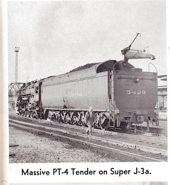
I was wondering if coupler lift bars ever pushed up the release pin from below rather than the more common lift up from above?  Reason I am asking is I am repairing a NYC PT tender and the brackets for the lift bar are below the coupler. I can't find any pics taken directly from the back of this tender and all the models I have have the bars cut short to allow movement of lobster claw couplers. I can imagine a bar being bent up and then over the coupler but would like to know for sure one way or the other.

Anyone with good pics of the rear of a PT tender would be appreciated.


Pete

Last edited by Norton
Original Post

Replies sorted oldest to newest

Originally Posted by Norton:

I was wondering if coupler lift bars ever pushed up the release pin from below rather than the more common lift up from above?


Virtually all passenger cars were bottom operated couplers, since the diaphragm and between-car striker/buffer plates, just above the couplers, interfered with top coupler lifting apparatus.


 Reason I am asking is I am repairing a NYC PT tender and the brackets for the lift bar are below the coupler. I can't find any pics taken directly from the back of this tender and all the models I have have the bars cut short to allow movement of lobster claw couplers. I can imagine a bar being bent up and then over the coupler but would like to know for sure one way or the other.

Anyone with good pics of the rear of a PT tender would be appreciated.


Try looking on the various books on NYC steam power, like Thoroughbreds, or "steam Locomotives of the NYC".


Pete


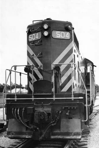
 I don't think I've ever seen a under-slung  operating lever on a steam or diesel engine.  Then again I haven't been on a diesel for over 20 years.   It's kind of hard to find pics of the rear of tenders when looking at engines. most of them  are side or front views. Most modern  rolling stock seems to have under -slung operating levers.

Thanks Hot. I did find a pic in Steam Power Vol 1 that is clear enough to show at least nothing above the coupler. The exact mechanism is not clear due to size of the photo but that will at least get me started. There are a few other pics in the other books mentioned that show 3/4 views of the rear or the shadows hide the mechanism.


Pete

Last edited by Norton
Originally Posted by Number 90:

Freight and passenger cars normally use the bottom lift uncoupling levers.


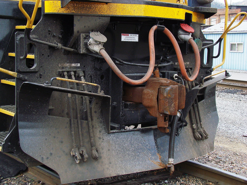
Diesel and electric ocomotives usually use top lift uncoupling levers, so that the coupler can be pinned from below to prevent the knuckles on couplers between m-ued locomotive units from being opened

Tom,

You sure you don't have that backwards? I've never seen a way to do that on the bottom of a top lift drawhead, while I have seen it done many many times on bottom lift drawheads in order to keep cars (such as ribbon rail cars) from coming uncoupled. 


I have never seen a top lift pin come up due to slack action, while a bottom lift is susceptible to lifting due to hard slack action causing the cut lever to swing up and lift the pin. 

I think Tom has it correct, There was a  clevis pin that was installed to keep the operating lever from operating.  For some reason I think it was on the bottom of the  drawbar that held the knuckle..  I was wrong about all diesel having top operating levers, F-3 were also under-slung.


Heavy snow banks could also uncouple a train with under-slung operating levers.


It's  hard to believe you've never had to switch out units on the road   and finding out you couldn't pull the pin because of the clevis, There are  usually hanging right there in plain view when not installed.


 Different railroads different strokes I guess . I've done it many many times. What would happen if someone accidently pull the pin ?  Jumper cable, walkway and chains ripped apart.

Last edited by Gregg
Originally Posted by Gregg:


It's  hard to believe you've never had to switch out units on the road   and finding out you couldn't pull the pin because of the clevis, There are  usually hanging right there in plain view when not installed.


 Different railroads different strokes I guess . I've done it many many times. What would happen if someone accidently pull the pin ?  Jumper cable, walkway and chains ripped apart.

As I said before...SHOW ME!

Last edited by Big Jim
Originally Posted by Big Jim:
Originally Posted by Gregg:


It's  hard to believe you've never had to switch out units on the road   and finding out you couldn't pull the pin because of the clevis, There are  usually hanging right there in plain view when not installed.


 Different railroads different strokes I guess . I've done it many many times. What would happen if someone accidently pull the pin ?  Jumper cable, walkway and chains ripped apart.

As I said before...SHOW ME!

It just dawned on me what he is apparently referring to. That little clevis & pin arrangement that physically connects the coupler lift pin bale, to the actual lift pin itself. Of course, this only applies to top lift coupler arrangements, as no such "lifting bale" is used in bottom operated couplers.

Originally Posted by Hot Water:
Originally Posted by Big Jim:
Originally Posted by Gregg:


It's  hard to believe you've never had to switch out units on the road   and finding out you couldn't pull the pin because of the clevis, There are  usually hanging right there in plain view when not installed.


 Different railroads different strokes I guess . I've done it many many times. What would happen if someone accidently pull the pin ?  Jumper cable, walkway and chains ripped apart.

As I said before...SHOW ME!

It just dawned on me what he is apparently referring to. That little clevis & pin arrangement that physically connects the coupler lift pin bale, to the actual lift pin itself. Of course, this only applies to top lift coupler arrangements, as no such "lifting bale" is used in bottom operated couplers.

But, he says..."There are  usually hanging right there in plain view when not installed." I've never seen anything like that. Besides, what you are referring to wouldn't prevent the pin from being pulled. It is required in order to pull the pin.


Last edited by Big Jim
Originally Posted by Hot Water:

If that clevis & pin arrangement is removed, then the cut lever arrangement is unable to lift the coupler pin. Now, it sure isn't easy to remove that cotter pin that retains the actual pin in the clevis, but once that little assembly is gone, or hanging loose, then the coupler pin can not be pulled up.

Well, that may be true. However, like I said before never, ever, have I seen that done. Nor have I ever seen a pin on any locomotive that had anything applied to it to keep the pin from being pulled. Nor, have I ever had a pin on a locomotive jump up and cause an un-dersired uncoupling.

Last edited by Big Jim
Originally Posted by Big Jim:
Originally Posted by Hot Water:

If that clevis & pin arrangement is removed, then the cut lever arrangement is unable to lift the coupler pin. Now, it sure isn't easy to remove that cotter pin that retains the actual pin in the clevis, but once that little assembly is gone, or hanging loose, then the coupler pin can not be pulled up.

Well, that may be true. However, like I said before never, ever, have I seen that done.


I have seen that done on only one occasion on a locomotive coupler, so that it could NOT be uncoupled from the special car it was attached to. Also, although I have never looked that close, I understand the CWR train sets have the clerics removed so that the couplers can NOT be uncoupled.


Nor have I ever seen a pin on any locomotive that had anything applied to it to keep the pin from being pulled.


I have never seen that set-up either.


Nor, have I ever had a pin on a locomotive jump up and cause an un-dersired uncoupling.


I have not witnessed, nor heard of, that either. I am aware of broken knuckles between units in an MU consist, but that is obviously a different subject.


I can't show you, (trust me I looked) and I also can't go back in time 60/70s.   This the best I can do. Read #5


Transport  Canada 

24. Draft Systems

24.1 A railway company shall not place or continue in service a locomotive with any of the following coupler related defects:

  1. a coupler shank that is bent out of alignment to the extent that the coupler will not couple automatically;
  2. a coupler knuckle that is broken or cracked on the inside pulling face of the knuckle, except that shrinkage cracks or hot tears that do not significantly reduce the strength of the knuckle shall not be considered cracked;
  3. a knuckle pin or thrower that is missing or inoperative;
  4. a coupler retaining pin lock that is missing or broken;
  5. a coupler with an inoperative lock lift or a coupler assembly that does not have anticreep protection to prevent unintentional unlocking of the coupler lock; locomotives in passenger service must be equipped with a device that locks the lock lift assembly to ensure prevention of unintentional uncoupling;
  6. a coupler lock that is missing, inoperative, bent, cracked or broken;
  7. a coupler not falling within the following heights above the rails, (except those by design and of which specifications will be filed with the Department):


Last edited by Gregg
Originally Posted by Big Jim:
Originally Posted by Gregg:

I can't show you, (trust me I looked) and I also can't go back in time 60/70s.   This the best I can do. Read #5


Transport  Canada 

Maybe you could draw a picture of this device that "Transport Canada" requires. I am curious as to what it looks like. 

 Sure thing , but later today... heading out  to work on a layout,

N&W marched to its own drum on mechanical details of its locomotives, and it would be no surprise if the Company used a different type of coupler than Santa Fe.  However, I can assure you that Santa fe and SP engines (other than cab and booster units) had top-lifting coupler pins and a hinged pin to insert through the bottom.  The pin, when fully inserted, became L-shaped as the hinged half dropped down, thereby requiring it to be manually removed rather than slipping out due to vibration.

Tom,

I don't think it is just an N&W thing. I have looked high and low and can't find a photo of any RR's couplers that shows a top lifting pin that has a part that goes through the bottom or something hanging down to put in said hole. The coupler section of my 1947 Loco Cyclopedia shows nothing of the kind. What kind of SF or SP units are you speaking of and what is the time frame?

Quanah, Acme & Pacific switch crews had rights to hostle locomotives.  That became necessary after the Frisco stopped basing a loco in Quanah...we would cut off the lead unit from the daily inbound, and use it to do our switching.  I say this only to prove that I have cut off locomotives every night I reported for duty.  We undid the chains and folded up the footplates, closed anglecocks for trainline, independent, main rez, and accuator...then pulled the jumper cable and finally the

pin.  Their was nothing special to unhook or remove on a Frisco set of loco s.  So yes, there was nothing that could prevent you from pulling the pin in the middle of a lashup, and tearing up a lot of stuff.

Last edited by Rob Leese

On a railroad I worked for many years ago we had a small series of rotary dump gondolas. These cars had a pin to prevent the coupler from uncoupling when the car was turned up side down.  It was pointed out that the Safety Appliance Act makes it against the law to have a coupler that requires someone to get in between the cars to uncouple it. We had to change out all the couplers in that series to more modern rotary dump car couplers that did not require anyone to get in between the cars to uncouple them.  I doubt very much that are any couplers in the US where a pin is placed in it to lock the pin from lifting. When we had trains, like welded rail, where we wanted to prevent unclouling, plastic tie wraps were used to secure the cut lever out at the side of the car.  The tie wraps could be cut without getting between the cars.  

Interesting info here guys. I appreciate it. Here is the reason for the original question. This is just part or an extensive repair required on a 3rd rail Super Hudson. All the unpainted brass is new. Replacement parts thanks to Precision Scale. More to follow on another forum when completed.

PT_repair1

Best prototype pic I could find.

NYC_J3_PT

Pete

Attachments

Images (2)
  • PT_repair1
  • NYC_J3_PT
Last edited by Norton
Originally Posted by Norton:

Interesting info here guys. I appreciate it. Here is the reason for the original question. This is just part or an extensive repair required on a 3rd rail Super Hudson. All the unpainted brass is new. Replacement parts thanks to Precision Scale. More to follow on another forum when completed.

PT_repair1

Best prototype pic I could find.

NYC_J3_PT

Pete

Nice Job Pete.  Under slung operating lever for sure on the tender.

Originally Posted by Gregg:
Originally Posted by Big Jim:

They don't look like top lift pins to me. The cut lever is on the bottom.

They are  are bottom lift.  I can't find a top operating lift but I'm sure they exist. .

Have you run across the bottom ones??  

No, all of our locos had top lift pins.

However, as I said before, I have seen many cars with the bottom lift pins "chocked" so they wouldn't lift. Even had to put a piece of wood in some problem pins on line of road to keep cars from uncoupling.

Last edited by Big Jim

Here you go Jim. You guys obviously aren't using the pins on freight. I know we did years ago but  I can't find any info on  our freight engines nowadays . (when I say ours I think Bill Gates owns them) It is  a must for  passenger trains  including Amtrak that enters Canada. Number 90 is also familiar with the pins . Having said that I can't find  a pic with the top operating lever and the pin in the bottom of the draw bar(that's where I remember it)  . On the other hand I guess we never stop learning things about railways even after we retire. I never realized how many different types of drawbars there were. Not a great pic but I don't know how to enlarge it. The pin is there near the top.

top operating lever

Attachments

Images (1)
  • top operating lever
Last edited by Gregg

 Derailment of  Amtrak train 188.... Did you notice the engine  had separated from the first car? The first car seems to have been ripped to pieces and I'm guessing  this is where  some of the fatal injuries occurred.   Do you think a  coupler locking pin might have helped keep the first car and engine coupled together?    Maybe there was one??


Originally Posted by Gregg:

 Derailment of  Amtrak train 188.... Did you notice the engine  had separated from the first car? The first car seems to have been ripped to pieces and I'm guessing  this is where  some of the fatal injuries occurred.   Do you think a  coupler locking pin might have helped keep the first car and engine coupled together?    Maybe there was one??


Just my opinion but, I really don't think any type of device would have kept that first car from being disconnected from the locomotive, after it was wrapped around that Catatinery support pole. 

Add Reply

Post

OGR Publishing, Inc., 1310 Eastside Centre Ct, Suite 6, Mountain Home, AR 72653
800-980-OGRR (6477)
www.ogaugerr.com

×
×
×
×
Link copied to your clipboard.
×
×