Recommended guidelines for retrofitting DCS to modular layouts.
THE PROBLEM
Most club standards involve some variation of a power buss daisy chained from one module to the next with one or more feeder sets (one wire per rail) on each module. The modules are also connected by the track itself. The buss is often connected into a complete circular path around the entire layout. All three of these features are problematic for DCS. Each connector between modules causes some portion of the signal to reflect back on itself. Go through too many connectors and there isn't enough signal for the engines to detect. Multiple feeder wires on the same length of track create looped paths that the DCS signal can travel for infinity. Looped signals can cause an engine to receive a command more than once or obliterate signal altogether. Looped paths are also created between modules via the track connection. Having the buss connected all the way around the layout creates the ultimate signal loop.
THE SOLUTIONS
1) Break the buss into groups of modules. The number of modules that each TIU can handle varies depending on your club's track configuration, wiring standards, and quality of construction. In the case of the Midwest Hi-Railers we found one TIU could handle up to about 12 of their modules with three mainlines and sidings. Each mainline gets powered by a separate TIU channel.
2) Locate the TIU near its group of modules. The chances of the DCS signal being degraded by reflections greatly increases when the total wire length from the TIU output to the track exceeds 16 feet. To get the most coverage out of each TIU they should be wired into the modules as close to the buss as possible. This has the added benefit of also putting the TIU's radio receiver near the controlled track. In public buildings with lots of wireless interference this can help a lot with remote/TIU communications. Power supply transformers can be located near each TIU or in one central location. Either way, the length of wire between the transformer(s) and TIU inputs has no effect on the DCS signal.
3) Isolate the center rail between modules. Some clubs use bridge track sections between modules. Others run the track to the edge and use pins to connect the sections. Whatever method your club uses, you should insulate the center rail(s) at each module. This will eliminate many if not all circular wiring paths.
4) Limit the feeders to one set per track per module. If your club uses more than one set of feeder wires on each module this creates a circular path for the DCS signal on each module. By limiting the feeders to one set per track per module in addition to insulation between modules you ensure that the DCS signal will have only one path from the TIU to the engine at any one time. Looped paths will still occur through the locomotive's internal wiring or through lighted cars that momentarily jump power between sections. However, these loops occur at or near the locomotive. The signal will be detected before it can degrade in the loop.
5) Add Deats filters. The signal filters developed by the son of forumite Susan Deats have proven highly effective at reducing interference with the DCS signal on buss wired layouts. You can find information about the filters, how to make them yourself, or purchase them
HERE. Ideally, one filter should be installed on each TIU output and one at the farthest point from the TIU. One way to achieve this configuration is to make a connector with a filter(s) that plugs into the buss at each end of a modular group. This makes it easy to install the filters at the farthest point from the TIU regardless of the modular configuration.
6) Change your remote and TIU settings. Because you will likely be using more than one TIU you will need to program each TIU into each remote. All TIU's will need to be set to "super mode" in each remote (MENU / SYSTEM / TIU SETUP / SUPER TIU). To maximizes the responsiveness of the remote you should also turn off remote messages (MENU / SYSTEM / REMOTE SETUP / REMOTE MESSAGES) and place the remote(s) in "speed mode" (MENU / SYSTEM / REMOTE SETUP / OPERATING MODE).
These next two obviously can't be applied in all circumstances. You can get good operation without them, but they do make things easier.
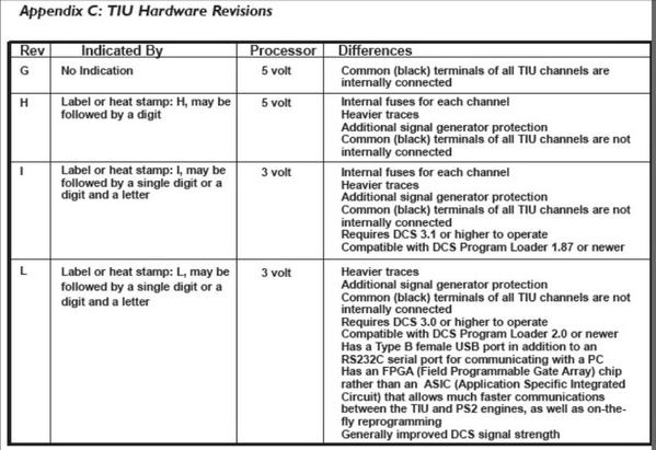
7) Use Rev. L TIU's when possible. The Rev. L TIU has stronger DCS signal generators than earlier revisions. If they are available to your club, you will get better results with Rev. L's.
8) Run PS3 engines when possible. PS3 engines have superior signal processors compared to PS2's. This allows them to accurately interpret a weaker DCS signal that has been greatly degraded. You will get more reliable operations with PS3.
![]()


