
It was 87 degrees in my office when I posted the prior pictures so I took the dog for a walk (it isn't any better outside!)and when I came back and looked in the barn, see (below) what had happened!  The left end platform top had been cut and installed and the 3rd level had been started on the right end.

Note that there's a pile of cork ready for installation and that Roy had painted the platform tops where the track goes and that the tape left a line for the cork and ultimately for the track.corner 2nd level piece cut and inplatform 1 level 23rd level started

Attachments

Images (3)
  • corner 2nd level piece cut and in
  • platform 1 level 2
  • 3rd level started

Some are. Some are kit bashed or simply adapted. When something is going to be historically accurate or site specific, the likelihood is that we'll create it from scratch or close to scratch. Although Fletcher is the primary person using his computer to draft 3-D images of the layouts to give clients a real feel for what there layouts will look like and how they'll fit into their space (and also to make adjustments if called for) and also does the drafting necessary for the CNC router, both he and Delia can create using the 3-D printer and the laser-cutter. (See bridge parts shown earlier on in this thread.) For our layout recreating the "el" and its elevated tracks as well as subway stations, a substantial number of historic buildings were created in the studio using research material rather than kits or kit bashes.

Dunham Studios posted:

Some are. Some are kit bashed or simply adapted. When something is going to be historically accurate or site specific, the likelihood is that we'll create it from scratch or close to scratch. Although Fletcher is the primary person using his computer to draft 3-D images of the layouts to give clients a real feel for what there layouts will look like and how they'll fit into their space (and also to make adjustments if called for) and also does the drafting necessary for the CNC router, both he and Delia can create using the 3-D printer and the laser-cutter. (See bridge parts shown earlier on in this thread.) For our layout recreating the "el" and its elevated tracks as well as subway stations, a substantial number of historic buildings were created in the studio using research material rather than kits or kit bashes.

Hi Barb, 

Thanks for all the great info. !!!

Alex 

This client originally requested Ross Custom track exclusively, which was fine with us as we have large stocks of both Ross and Gargraves on hand.  But on the previous job, "The Basic Layout", we discovered that the anodized center rail on Ross Track was resistant to reliable Digital Signal Transmission, resulting in the necessity of multiple routine cleanings with abrasive cleaning pads, over a period of weeks, actually months.  We have no assurance that this is not a continuing problem which will require constant reapplications of the same cleaning techniques.  This would, at minimum, be a decided pain in the derriere.  If anyone out there has any further information about this problem, which appears to worsen when both MTH and Lionel control systems are involved on the same layout (a more and more common thing), we would be more than happy to hear about it.  I must add that the problem does not exist with Gargraves Products.   We were planning to switch this track system to Gargraves Track.  However, the client has still insisted on Ross Track though I have opposed it.  However, as "The client is always right", he will get what he wishes, and perhaps deserves.

Clarke

All I can tell you you that the trains, yes, mostly MTH--the client owns mostly MTH trains--suffer substantially irregular Digital Reception unless heroic cleaning measures are taken on the center rail of Ross Custom trackage.  And this is the second project that we have noticed this phenomenon on.  Take away the digital requirement, the Ross product functions ably.  It's not the quality of the track's construction, it's this particular digital requirement.  I understand that the chemical process involves the material being dipped in a chemical solution.  But here, I have to say that I just design 'em, I'm not he guy who electrifies 'em.  Barb and I are just the guys who run the company.  And I'm certainly not the guy who understands why, when the rest of the world has only one Digital Standard---DCC---why we have two otherwise clever companies creating this dance of death for their customers.  I can also not tell you why Gargraves track products do not have this problem.

Clarke


Last edited by Dunham Studios
StPaul posted:

... track pin connections is another dcs signal killer when they loosen up due to expansion and contraction with climate change.


This past weekend I spoke to Mike Wolf during his visit to Nicholas Smith Trains, and I thanked him for following through on the delivery of MTH ScaleTrax #4 and #6 turnouts... and that I now had no excuses for not starting my layout!    Mike made a point of suggesting that ALL track joints be soldered when building a permanent layout.  ALL OF THEM!!!

David

P.S.  I also want to point out how impressed I was that Mike himself was doing the DCS 5.0 upgrades.  He upgraded my TIU and the remote to go along with it.  Then he showed me how to use my iPhone to control a small train on one of the display layouts via the DCS WiFi unit (which I purchased while I was there).  Really cool technology, that I had also seen at York.  But it was nice having Mike show me a few nuances to it.  How many CEO's know anything about their company's products nowadays?    Much less be able to actually roll up their sleeves and get their hands dirty with the actual products.  That goes a long way in my book.  And I'm glad our industry still has a guy like Mike Wolf at the head of the company he started.

Last edited by Rocky Mountaineer

A difficulty that I have had with Ross track is that it does not like vertical curves i.e. the top and bottom of grades. The rails exert a  force when bent vertically, that eventually causes the spikes to loosen, then uneven track and derailments. This is similar to to the forces when the track is bent into a curve however the spikes are positioned in the ties so as to resist a horizontal force but bending upwards or downwards will pull the spikes out of the ties.   

Dunham Studios posted:

This client originally requested Ross Custom track exclusively, which was fine with us as we have large stocks of both Ross and Gargraves on hand.  But on the previous job, "The Basic Layout", we discovered that the anodized center rail on Ross Track was resistant to reliable Digital Signal Transmission, resulting in the necessity of multiple routine cleanings with abrasive cleaning pads, over a period of weeks, actually months.  We have no assurance that this is not a continuing problem which will require constant reapplications of the same cleaning techniques.  This would, at minimum, be a decided pain in the derriere.  If anyone out there has any further information about this problem, which appears to worsen when both MTH and Lionel control systems are involved on the same layout (a more and more common thing), we would be more than happy to hear about it.  I must add that the problem does not exist with Gargraves Products.   We were planning to switch this track system to Gargraves Track.  However, the client has still insisted on Ross Track though I have opposed it.  However, as "The client is always right", he will get what he wishes, and perhaps deserves.

Clarke

Use a separate transformer for the switch power rather than the accessory port of the track transformer.(Z1000 brick) If you must use the same transformer, try a 22uh choke in series with the hot to each switch machine. Especially if you have DZ2500 switch machines. I assume that RCS switches are being used.


Thanks Carl,

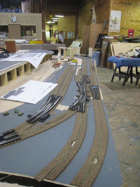
Been there, done that.  We use separate switch machine power and accessory power on all our layouts.  That's why we're surprised that the problem still exists.  The only thing that clears this problem is a thorough cleansing of the Ross center rail's coating.  The solution in this case is to be Gargraves track with wood ties (in view) and plastic ties in the tunnels which have recorded no such problems .  But always Ross Custom Turnouts and Z-Stuff Machines.  Since the first and primary object in my mind is to have the layout run properly, the fact that one product appears to have spikes and the other one doesn't (but runs better), you can only guess my preference.  After 25 years and literally millions of viewer/visitors (not to mention very vocal "advisors") at the Citigroup Layout, you learn to appreciate what's reliable--first!   After that, you can discuss the beauty of rail spikes with me.  Thanks for the ideas.

Rocky Mountaineer and St Paul: 

More good ideas!   Interesting hearing about Mike Wolf's unfailing personal connection to his products.  Makes you wonder about that "other" company out there.  But Mike's always been like that.  Years ago, we did a custom layout for Mike for OpryWorld in Nashville.  Mike was right there in the middle of the setup, programming locomotives.  That's just his very professional style.  After OpryWorld, the layout was at York for several seasons. 

Clarke

Last edited by Dunham Studios
Dunham Studios posted:

All I can tell you you that the trains, yes, mostly MTH--the client owns mostly MTH trains--suffer substantially irregular Digital Reception unless heroic cleaning measures are taken on the center rail of Ross Custom trackage.  And this is the second project that we have noticed this phenomenon on.  Take away the digital requirement, the Ross product functions ably.  It's not the quality of the track's construction, it's this particular digital requirement.  I understand that the chemical process involves the material being dipped in a chemical solution.  But here, I have to say that I just design 'em, I'm not he guy who electrifies 'em.  Barb and I are just the guys who run the company.  And I'm certainly not the guy who understands why, when the rest of the world has only one Digital Standard---DCC---why we have two otherwise clever companies creating this dance of death for their customers.  I can also not tell you why Gargraves track products do not have this problem.

Clarke


Clarke,

You might want to take a look at the real reason for this.  I would suspect other things such as wiring, outside rail to outside rail continuity etc.  It is common for owners of poor performing layouts to blame DCS.  I would be happy to offer assistance.

Dave

Thanks, Dave, but since this is something like our 58th layout, we're quite on top of our electronic abilities.  That's why Dunham Studios hires professionals in every department.  No it's not our wiring.

Carl, Glad you noticed the Farm Stand.  It's one of the very few Plasticville models that hold up in a realistic setting.  We've used it over and over again.

Clarke

Last edited by Dunham Studios

Delia's starting to build the skeleton for the right-hand mountain. She measures, marks, cuts and installs each piece out of Dow foam sheets. When the skeleton is complete, she will 'flesh it out' by overspraying with insulation foam. (Canisters thereof like they insulate your attic, not the little containers from the hardware store.) Note that what appears to be the top of the mountain is flat. That's because it's not the top which will be a separate piece so she can work on it on a table and not have to worry about hanging off a ladder. But that's still a ways off.

BarbDelia measuring mountain topbuilding skeletal structure for mountainopen view of mountain structural formskeletal mountain form with structural wing

Attachments

Images (4)
  • Delia measuring mountain top
  • building skeletal structure for mountain
  • open view of mountain structural form
  • skeletal mountain form with structural wing

Delia's added 'wings' to the mountain frame to broaden it. She reminded me that having the mountain top removable was not just so she could work on it on a table rather than hanging off a ladder but also and primarily so the piece could get through the client's door! (Oh yes, that. None of this "boat in the basement" for us at Dunham Studios.)

Barbadditional 'wings' to broaden mountainmountain frames

Attachments

Images (2)
  • additional 'wings' to broaden mountain
  • mountain frames
Dunham Studios posted:

Thanks, Dave, but since this is something like our 58th layout, we're quite on top of our electronic abilities.  That's why Dunham Studios hires professionals in every department.  No it's not our wiring.

Carl, Glad you noticed the Farm Stand.  It's one of the very few Plasticville models that hold up in a realistic setting.  We've used it over and over again.

Clarke

Clarke,

Since you mention the wiring, I was curious about the green wire down the center of the roadbed. What is the purpose of that wire?

Hi Carl,

It's a ground wire for the DCS transmission.  We just do it because when it's absolutely necessary, it's also too late if you haven't done it.  It appears to be especially necessary when you have, as in this layout, trains crossing on top of trains crossing on top of trains.

Clarke

PS: I've just been corrected by my Command Control Specialist--it's actually the "Ground Plane" for Lionel TMCC, not DCS.  And we put it there because it's required, though there are other methods of placing it.


Last edited by Dunham Studios
Dunham Studios posted:

Thanks, Dave, but since this is something like our 58th layout, we're quite on top of our electronic abilities.  That's why Dunham Studios hires professionals in every department.  No it's not our wiring.

Carl, Glad you noticed the Farm Stand.  It's one of the very few Plasticville models that hold up in a realistic setting.  We've used it over and over again.

Clarke

Clarke,

Hello, I didn't mean to offend you but if your DCS is not working correctly, something is wrong.  I cannot boast about building 58 layouts but I have put together quite a few and DCS works on them.    When your signal strength goes down, there is a reason for it and that reason is not DCS.

Dave

Here's a drawing of this part of the layout containing the stone arches and the trestle....and where Delia's put the parts temporarily into place to give her an overview so she can begin to shape the mountains from the front  She's cut 'wings' all around to give the right hand mountain dimension which you can see when you look at the photo of mountain from the back and the removable mountain top.

Barbdrawing of trestle and stone archesstone arches for bridgetrestle supportsthe mountain from the back sideremovable mountain top frame

Attachments

Images (5)
  • drawing of trestle and stone arches
  • stone arches for bridge
  • trestle supports
  • the mountain from the back side
  • removable mountain top frame

Tom and Mike are speedily laying track. The cork was just painted this morning by Delia who stopped her mountain work to paint cork and was working right in front of them. With the cork painted Delia needed to get back to her part of the layout, the scenic part, mountains and bridges and trestles, oh my. So she separated the trestle section from the rest of the layout in order to be able to work without either being under foot or having the guys under foot. Note that the mountain top is removable and the trestle section is removable.

BarbTom and Mike laying trackMike laying trackDelia measuring for trestle-2

Attachments

Images (3)
  • Tom and Mike laying track
  • Mike laying track
  • Delia measuring for trestle

Clark,


Is the cork road bed over the plywood really enough to take the sound out of the running trains without adding homasote or other sound deadending materials, for the gargraves track? Where can I purchase for ogauge track with 72 curves as well as STD gauge with 72 curves.

She is pretty talented with that foam. All of you do a nice job!!

JoeG

Roy is placing some of the arch tops he cast while Delia has returned the trestle section to its actual location. Notice how the curved wooden area seems to deadend at the trestle section? That's where the track will go onto the trestle...when the trestle is in place. As a bonus, we've put a couple of buildings roughly where they'll be installed.

BarbRoy placing tops of archesarch tops clamped in place Delia working on trestle areatrestle section back in placecurve going into trestlebuildings roughly placed

Attachments

Images (5)
  • Roy placing tops of arches
  • arch tops clamped in place Delia working on trestle area
  • trestle section back in place
  • curve going into trestle
  • buildings roughly placed

With three levels of track already laid, Tom and Mike continue with track and wiring while Roy gets his bridge arches installed in place. Take notice in the photo "bottoms up" that the trestle section of the layout has once again been removed. In the last photo in this series you'll see that section as a free-standing unit on the barn floor. Note that Delia has begun to place "rubble" around the trestle footings. This "rubble" will be covered over with blown foam which she will then carve, paint and scenic.

Barb3 finished levels of trackTom, Mike and Roy at workbottoms up!Mike Burke doing trackwork across from Roy's archesarches in place'rubble' filling in around trestle footings

Attachments

Images (6)
  • 3 finished levels of track
  • Tom, Mike and Roy at work
  • bottoms up!
  • Mike Burke doing trackwork across from Roy's arches
  • arches in place
  • 'rubble' filling in around trestle footings

Add Reply

Post

OGR Publishing, Inc., 1310 Eastside Centre Ct, Suite 6, Mountain Home, AR 72653
800-980-OGRR (6477)
www.ogaugerr.com

×
×
×
×
Link copied to your clipboard.
×
×