I have an MTH Galloping Goose PS1 that I would like to automate for our public display at the McCormick Stillman Park. The station stop action needs a three second DC negative on the power line.  I tried the suggested seven diodes in a series with one diode opposite and it worked but the Goose dropped its speed, as anticipated, during the three second period, then speed up for a second before stopping. Looked goofy!

Can anyone recommend an electronic method that works like the bell button on the Z4000.  That one is great, but we need to get the PS1 working with our track side control system, and for that we need to be able to send the pulse without reducing the speed significantly.

Essentially a microprocessor will be built into the engine to read a track side IR code transmitted at locations along the right-of-way. After reading the code the microprocessor can operate a relay to give the three second pulse. The missing link is a viable negative going DC on the power line.

Thanks,

Paul Boston

Original Post

Replies sorted oldest to newest

Thanks John.  

The P&P layout has a thousand feet of track and adding any separate transformers and segmenting several short track segments would be problematic. Our layout is open to the public for viewing and interaction and we have 60 members and park employees that can/may/will operate the layout, so everything must be easy to operate and transparent.

What I am hoping for is a "bell button" equivalent that we can mount inside the Goose and activate using our trackside codes.

Your response was appreciated.

Paul

Hi John,

Working from the inside the Goose is the go-forward plan.  The IR code generators and sensors are already in use with other engines and a streetcar, now it's just to find an elegant way of getting that negative DC pulse generated from inside the Goose.

Your response and comments have been appreciated and helpful.

Thanks,

Paul Boston

Thanks for the response and the diagram. I'll give it a try on my test loop where there is only one train, which will simulate an internal installation without using a screwdriver. What it lacks in elegance it makes up for in simplicity. ;-)

Thanks again.

These motors run well on low voltage so applying the typical 12VAC to the track should give adequate performance. The track voltage from 0 to 22VAC is available.

Considering your somewhat unusual situation of having the knowledge/ability to add custom programmable electronics to your engine, here's another idea.  Why not find out where the engine's stock electronics senses the DC offset for bell/whistle.  It probably uses an A/D converter or a DC offset comparator to measure a scaled-down version of the track voltage.  Then just inject what probably amounts to a milliamp or so of -DC offset into that node when you want to trip the bell.  The motor drive DC voltage would be derived from unaltered track voltage so the speed would not change...and there's no diode drops wasting power (not that anyone said wasting power is an issue).

The electronics in the engine are an unknown quantity with regard to how signals are processed. Suffice it to say that the heart of the control system is based on being able to detect positive going and negative going DC voltages sent as a series of pulses that are then processed by, as you suggest, a A/D converter, and the pulse chain uses a lookup to determine the action to be taken.  All of these actions take place when the engine is first powered up and the voltage has not been advanced beyond 10 VAC. After the 10VAC is applied the horn blows when a positive voltage is applied and the bell latches and unlatches with a negative pulse.  If the negative pulse is sustained for more than three seconds the flag-stop sounds begins and when the negative pulse ceases, the action begins. (letting go of the bell button)

A battery could supply the DC if it would be safe to momentarily apply the battery to the incoming AC power using a DPDT relay. I'm just not sure that's safe for the equipment.

Last edited by Just-a-Runner

I think the battery is safe for the several seconds of use.  Part of your description is wrong. None of this works until the engine leaves the first reset state. (first power up).  After the first direction cycle the engine is now permanently out of reset state until the next power down for 5 seconds or more.  So after that cycle the engine is in fwd, reverse or neutral and the offsets do various features depending on state, voltage and duration of pulse.  Also it is not series of pulses it is a constant offset for the period of holding down the button.

I do think using the diodes with a compensation voltage when Triggered would be the simplest method.  Or use a 2.4V battery source.   G

Thanks GGG for clearing up the reset state.  My confusion arose from using other MTH engines that used the bell and whistle buttons in the reset mode to change the programming. I appreciate the enlightenment.

I am leaning toward the 2.4V battery at the moment.

Thanks also to John for the input.  The reason for the internal modification is to make the Goose respond to trackside IR code transmitters. Because the layout operates for, and often by, the public as well as by members with their own trains, configuration of  the layout as a whole needs to be as generic as possible to provide access to all members. Each of the four loops of track is about 125 feet long and serviced in quadrants +1 by five TIUs, a TMCC, and Lionel Legacy control system.

The Goose will have to be isolated as much as possible from the rest of the layout, be set up for automatic running and be easy to start, stop and remove when its operation isn't desired or it needs service.

Thanks again for the feedback.

Paul 

Just-a-Runner posted:

The electronics in the engine are an unknown quantity with regard to how signals are processed....

Relay with diode string or battery are simplest.  I only suggest touching the PS1 electronics if dabbling with circuit design is what makes the hobby interesting to you.

Processor-based engines using A/D converters to detect DC track voltage offset might be functionally represented as follows:

Untitled

The AC track voltage which can swing 50 V peak-to-peak must be scaled down to, say, a 0-5V pk-to-pk to map into the range of the A/D.  A couple resistor can do the scaling.  Additionally, a small +DC bias must be inserted so that the A/D converter gets a mid-scale voltage when there is 0 track voltage.  A third resistor can supply this positive DC bias shown here coming from +5V.  This circuit is independent of the circuit that drives the motor.

To implement an electronic bell trigger, the custom IR microprocessor could drive a 25 cent optocoupler (instead of driving a relay).  The optocoupler output would sink current from the "magic node" where the A/D measures the track voltage.  Some 2 cent resistors aren't shown in the diagram but would be chosen based on how much the DC must be lowered at the magic node when the bell is activated.  When the -DC offset is triggered, the AC track voltage is not affected and the motor speed does not change.  So the new components to implement the bell trigger would be less than 50 cents. 

The same technique could be used to simulate a horn trigger by raising the voltage at the magic node with another optocoupler.  For example a trackside IR sender could trigger the onboard IR microprocessor to generate short-long horn sequences at grade crossings.

If you designed your IR microprocessor circuit and the PS1 electronics to run on the same DC power supply common, you don't need optocouplers and the added component cost would be a dime or so for a few resistors.

Attachments

Images (1)
  • Untitled
Last edited by stan2004

Hi Stan.  You have me salivating over the possibilities you described.  I have the opt-isolator and a gaggle of resistors at hand.  Your picture didn't come thru but I sure am interested!

I've used opt-isolator with Picaxe before so that part will be easy. The voltage scaling and +DC bias are things that are familiar so, with the diagram there can perhaps be a "magic node" soon inside the Goose.

Your patience is appreciated since all my electronic experience is self taught and I didn't get started until the age of 69. That jump start was at a Garden RR convention in Phoenix and was inspired be Dave Bodnar who has written for the Garden RR magazine. Consider your assistance as helping keep the old-age symptoms at bay.  ;-)

Thanks,

Paul

I reloaded the picture so hopefully it is now viewable.  Of course it was always viewable to me so who knows.

It is not a slam-dunk.  The trick is to find that magic node where the PS1 engine scales down the track voltage...then to inject a small (milliamp range) positive or negative current to fake the PS1 electronics into thinking there's a positive or negative DC offset on the track voltage.  As mentioned if your IR microprocessor is on a separate DC common as the PS1 electronics common, you should probably just use an opto-coupler.  I don't want to insult you if all this is old-hat, but the idea is to drive the opto-coupler LED from a digital output from the microprocessor...probably the same pin you were planning to use to drive the relay for the diode/battery method.  In general you need to drive the opto-coupler LED via a resistor.  Then use the CTR or current-transfer-ratio spec of whatever opto-coupler you have to estimate how much current the opto-coupler transistor will sink from the magic node.

Obviously the first step is to find that magic node (assuming it exists).  I'm not knowledgeable about how many different versions of PS1 boards exist.  Maybe one of the other guys knows.  But if you have the ability to post a photo of your PS1 board, I have a few PS1 boards in a box somewhere that I've since upgraded to PS2.  And I will see if I have a similar PS1 board and make a stab at finding that magic node.  I realize this is a one-off but it would make a good story!

Hi Stan,

The picture looks great and it makes the whole thing clear. The additional explanation is very valuable in that it defines the underlying characteristics of the circuit that need to be addressed. NONE of this is "old hat" for me and the explanations are much appreciated.

The idea that the magic could be injected with a positive pulse to sound the horn adds another possible action. Using a different Sony code for another IR transmitter and/or transmitting the code(s) from certain IR transmitters on an alternating basis would give boundless variety to the scene. I can't wait to see this expand! Between having varied codes from the fixed processors and sequencing (even randomly) the response to codes within the Goose would be delightful.

Now to get it going. I'll take this Goose apart and forward the circuit board photo.

Thanks a LOT!

Paul

Just-a-Runner posted:
...Attached are the photos showing the two boards...
I finally found my box of old PS1 boards and I think I have the same board as what you show.  I peeled the label off the large chip and it appears to be a NEC D7823 which indeed has A/D input capability (8-channel, 8-bit).  So that's a start. 
IMG_1153
My next step is to see if I can figure out (remember) how to power up the board with AC track voltage and see if it still works and the sound starts up!  If so, I can poke around to hunt for the magic-node.  The ideal result would be if the magic-node or proxy is one of the 2 x 8-pins that inter-connects the top and bottom board.  In any event, the objective is to inject a small negative current and trigger the bell, and/or inject a small positive current and trigger the horn.
 
Upon reflection, the code you need to write for your IR processor is the same whether you use the relay method (with diode string or battery) or the magic-node method.  That is, in both cases your IR processor activates a digital output to trigger the bell; and another output to trigger the horn.  In the relay case, the output drives a transistor which then drives a relay coil.  In the magic-node case, the output drives an opto-coupler.
 
If you've already gone the relay route, let me know and I'll cease and desist.


Attachments

Images (1)
  • IMG_1153

You guys are GREAT!  I am eager to see what Stan discovers regarding the ADC input pin. I wish I could help, but It's out of my league.

The microprocessor is a Picaxe (PIC chip) and the route of transistor to relay is one of my well trod paths. I use a 5VDC relay (DPDT cause that's what I have), a 2n2222 NPN transistor with protection diode. Not elegant, to be sure, but it works.

Experiments with diode arrays have pointed to using five diodes each way and a switch as in this diagram. This configuration causes the least speed change and operates the bell every time. Adding or removing diode pairs caused bot positive and negative speed changes. The Goose without diodes runs fine at 9+VDC and with the diodes it takes 12VDC, a very acceptable value, with a current draw of less than one amp. Since the diodes are internal to the engine and will only be handling the engine electronics and motor, low power diodes seem in order. I used 1 amp diodes 4001 and they seemed just warm after a half hour run. 

Finding room inside the Goose will be challenging but the added electronics are not too large. It will be close.

Attachments

Images (1)
  • Screen Shot 2016-08-24 at 7.58.45 PM

So here's my progress so far.

PS1 analog input pins

Based on the datasheet, I measured the A/D reference voltage on the D7823 chip (pin 77 or AVref1) and it is 5.0V DC...so I'm looking for an analog voltage in the 0-5V range that changes with DC offset on the track.  I could not find a 0-5 VDC signal on the 2x8 inter-connect headers that materially changed with a transformer Whistle or Bell button press.  But in examining two of the A/D input pins (AN0 and AN1) I found the following interesting results.  With 13.5V AC on the track using a Z-4000, I pressed Whistle and Bell buttons.  The Z-4000 put +2.27 V DC (Whistle) and -1.56V DC (Bell) offsets on the track.

AN1 measured: 4.01V, 3.88V, 3.78V for Whistle, none, Bell.

AN0 measured: 3.72V, 3.88V, 3.97V for Whistle, none, Bell.

These are DC voltages though the actual signals are clipped track voltage waveforms (confirmed by an oscilloscope).

So there's some kind of differential behavior with AN1 increasing and AN0 decreasing for a positive DC offset (Whistle button) on the track.  I suspect the processor chip might be measuring the delta between the two signals to decide if an offset is present.

The interesting result is I could trigger the Whistle or Bell by simply applying +5V DC or Ground via a 1K resistor to one of the pins.  More tests as time-permits...

----------------------

Edit: additional info:

With 13.5V AC on the track using a Z-750, I pressed Whistle and Bell buttons.  The Z-750 put +3.15 V DC (Whistle) and -3.33V DC (Bell) offsets on the track...substantially more DC offset than the Z-4000.

AN1 measured: 4.46V, 4.21V, 4.04V for Whistle, none, Bell.

AN0 measured: 4.06V, 4.21V, 4.45V for Whistle, none, Bell.

Again, I was able to trigger the audio by injecting a small current (well under 1 mA) into just one of the A/D pins.  The changes in A/D pin voltages in response to button presses increased with the larger track DC offsets; so it's a reasonable indicator that these pins might be the magic nodes.  Also the idle voltage (no button pressed) also changed which makes sense since the Z-750 and Z-4000 track voltage waveforms are materially different (chopped vs. smooth sinewave).

Attachments

Images (1)
  • PS1 analog input pins
Last edited by stan2004

ps1 bell whistle 3 wire connection

ps1 bell whistle opto hack

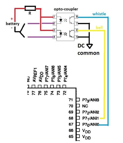
Based on previous post results, I concluded you can "pull-down" the ANI1 A/D input line to trigger the bell, and "pull-down" the ANI0 A/D input line to trigger the horn/whistle.  It appears you only need to pull it down by about 1/4V or so to trip each audio function.  From empirical data, this 1/4V drop can be induced with only about 500 uA (microAmps) which is easy to generate from virtually any opto-coupler in existence.

So I hooked up a dual opto-coupler (one for bell, one for horn/whistle).  I just used a 2.4V battery (2 x 1.2V AA rechargeables) to simulate the IR processor that would be generating the digital bell (and/or horn) triggers.  Since the opto-coupler outputs are less than 1 mA, the opto-coupler input drive to the LED is also trivially small (less than 1 mA) to it could even be directly driven (no buffer transistor or whatever) from any digital output pin of a microprocessor module.  In other words, the battery in the diagram would be replaced by digital outputs from the IR processor.

In the example, the resistor in series with the opto-coupler LEDs was 4.7k.  The forward voltage of an opto-coupler LED is about 1V.  So coming from a 2.4V battery, the LED current was only (2.4V-1V) / 4.7k = 300 uA.  And here's a video showing the bell and horn/whistle triggered by selectively driving the corresponding opto-coupler.

I found the DC common for the PS1 audio-board on the 3rd pin of one of the 8-pin headers as shown in above photo.  Obviously if you only want to trigger the bell, it could be just a 2-wire connection.  This does require some careful close-quarters soldering to attach the wires to the PS1 processor A/D input pin(s).  I'm sure the same nodes exist elsewhere on the board with potentially easier solder-ability but I didn't look. 

Since it appears you can fit the components for the relay/diode method in your engine, that is certainly the more straightforward method.  So this could be a potential back-up last resort option if plan A does not work out for whatever reason.

Attachments

Images (2)
  • ps1 bell whistle 3 wire connection
  • ps1 bell whistle opto hack
Last edited by stan2004

Add Reply

Post

OGR Publishing, Inc., 1310 Eastside Centre Ct, Suite 6, Mountain Home, AR 72653
800-980-OGRR (6477)
www.ogaugerr.com

×
×
×
×
Link copied to your clipboard.
×
×