I am attempting and upgrade to my Lionel Polar Express O Gauge Berkshire with an ERR Cruise Lite and Sound Converter Upgrades.  The locomotive is from set 6-31960 from around 2003 and I have The Polar Express™ Steam TrainSounds Tender 6-36847 (circa 2009) which includes steam chuffing, steam whistle, bell, squealing brakes, and operator-controlled multi-part crew dialog.

The whistle and bell do not function via the Cab-2.  The sound board is working as I hear chuff when moving.  I am able to trigger whistle and bell from the transformer through the locomotive to the tender via the red and black wires from the Converter to the Sound Board.   The sound board is not connected directly to rail power.  The tender sound board has the following markings:

691-ISNO-B

E159194

Sigs/3.3/Gnd/Chuff/S+/S-

However, according to Lionel it is currently listed as fitted with 691ISNDGST TRAINSOUNDS / GENERIC STEAM. 

I have tried programming the PE to Feature Code 0 (Steam w/Signal Sounds) but the engine rockets down the track when powered up.

I currently have it programmed for Code 4 (Steam w/Rail Sounds).  The loco does move forward and backwards using either Cab-2 or Cab-1. Could the issue be with the programming info on the Cab-2 Legacy controller?  I have tried TMCC, and CAB-1 settings.  I have tried NO RS, RS settings but nothing is allowing for remote bell and whistle. 

BTW, the front headlight seams to stay on in forward and reverse.  Not sure if that means anything.  I have the hot to lamp connected to terminal 4 but nothing connected to common terminal 5 since the bulb socket is grounded to the chassis. 

I am not sure how to "reset" the boards since that information is not included in the ERR instructions.

Original Post

Replies sorted oldest to newest

It sounds like you aren't getting it programmed properly.  Do this, this is the "reset" of the ERR Cruise Commander board.

  • RUN/PGM switch to PGM
  • ENG, ##, SET
  • AUX1, 4
  • RUN/PGM switch to RUN

FWIW, as a steamer, the headlight does stay on all the time.  The key test is does AUX2 toggle the headlight on and off?

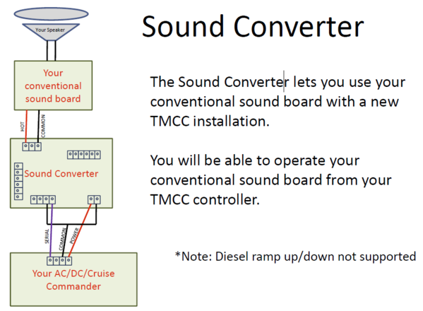
As far as the Sound Converter, how do you have it wired.  It should be supplying the power to the sound board, that's the way it controls the sounds.  The simple diagram they offer shows the wiring, if it's wired this way, it should be able to simulate the whistle and bell.  Note that any power to the sound board MUST go through the Sound Converter board.

ERR Sound Converter

Attachments

Images (1)
  • ERR Sound Converter

Well, there are some LED drivers on the Sound Converter as well, and those react to whistle commands.  The six pin connector has three LED's connected,

Here's a thread where I demo the LED connections for the sound converter.  If you just wire up one LED to the six-pin connector, you can see if it reacts to serial data.

https://ogrforum.ogaugerr.com/t...52#70974704561814252

Well, it appears the Sound Converter is actually providing the offset, I wonder if the voltage drop through the regulators is affecting the ability of the board to sense the whistle?  Have you tried upping the track voltage?

FWIW, when I tried one of these on the bench, it had no issue triggering the whistle or bell of a Lionel conventional sound board.

Well no luck with ERR.  Ken sent the board back stating it works as it should.  I turn back to the team here on OGR to try and solve this.   I have it installed as shown in the figure above.  My earlier reports for voltages were not corrected were RMS (I use Lionel CW-80s).  So the corrected numbers are:

Track voltage 18.4 AC

Sound Converter output (measured across red/black):

No whistle activation17.1 VAC, -0.07 VDC

CAB2 whistle 15.0 VAC, 2.3 VDC (not work)

Transformer whistle 16.8 VAC, 1.4 VDC (works)

Any ideas?


gunrunnerjohn posted:

It sounds like you aren't getting it programmed properly.  Do this, this is the "reset" of the ERR Cruise Commander board.

  • RUN/PGM switch to PGM
  • ENG, ##, SET
  • AUX1, 4
  • RUN/PGM switch to RUN

FWIW, as a steamer, the headlight does stay on all the time.  The key test is does AUX2 toggle the headlight on and off?

As far as the Sound Converter, how do you have it wired.  It should be supplying the power to the sound board, that's the way it controls the sounds.  The simple diagram they offer shows the wiring, if it's wired this way, it should be able to simulate the whistle and bell.  Note that any power to the sound board MUST go through the Sound Converter board.

ERR Sound Converter

John, went nuts with the program of a firecar... the bell was ringing random etc.

i went nuts with the cab 2 as there are no numbers on the keypad. Icon based. I know the area where the icons are  suppose to  correspond to numbers...But, programming seemed to be a issue this way.  When, I did get it workin ...here is the procedure. He can hit eng ID set. It will now be set to the I'd. Keep power on and touch nothing. 

Hit to the info key ..traverse to aux tab..enter the feature code 4... turn down power and set the switch to run...I never did get it to program the other way..


The horn sounded on the I'd set. Then again on the feature code...I was having the same problem..the horn would work ..not the bell..the horn would go off intermittent...threw me for a loop.

Last edited by shawn
Steims posted:

Actually that is full voltage from my CW-80...  

Is there some restriction about using chopped-sine track voltage into the Sound Converter.  Some member by the name of gunrunnerjohn posted CW-80 "full throttle" waveform photos a while back in another thread:

cw80 full throttle

Since the Sound Converter apparently inserts DC offset onto this waveform I suppose one could imagine how the results might vary depending on the shape of the incoming AC track voltage.  Presumably most guys using this Converter are operating in a command environment with 18V AC "pure" sine from a PH180, ZW, whatever.

Separately, when you corrected the voltage measurement numbers above, was this by using a different meter?  You mentioned RMS.  Depending on the meter, you can get confusing AC voltage readings with chopped sine and/or chopped sine with DC offset.

Attachments

Images (1)
  • cw80 full throttle
stan2004 posted:
Steims posted:

Actually that is full voltage from my CW-80...  

Is there some restriction about using chopped-sine track voltage into the Sound Converter.  Some member by the name of gunrunnerjohn posted CW-80 "full throttle" waveform photos a while back in another thread:

Since the Sound Converter apparently inserts DC offset onto this waveform I suppose one could imagine how the results might vary depending on the shape of the incoming AC track voltage.  Presumably most guys using this Converter are operating in a command environment with 18V AC "pure" sine from a PH180, ZW, whatever.

Separately, when you corrected the voltage measurement numbers above, was this by using a different meter?  You mentioned RMS.  Depending on the meter, you can get confusing AC voltage readings with chopped sine and/or chopped sine with DC offset.

Just for you, Stan!

Fed my CW-80 into a Legacy Powermaster. I have a Williams GP-9 that has a Cruise Lite, Sound Converter and Tru-Blast II.

Basically, everything works fine at full voltage, but the bell/whistle does not work when either the CW-80 or the Powermaster are set below about 60%.

FWIW, I tested all three ways to sound the bell/whistle. They work from the CW-80 buttons, they work via TMCC from the Cab-1L, and they work with the Cab-1L controlling the track voltage via the Powermaster.

Not sure that proved anything, but it is another point of reference.

stan2004 posted:
Steims posted:

Actually that is full voltage from my CW-80...  

Is there some restriction about using chopped-sine track voltage into the Sound Converter.  Some member by the name of gunrunnerjohn posted CW-80 "full throttle" waveform photos a while back in another thread:

cw80 full throttle

Since the Sound Converter apparently inserts DC offset onto this waveform I suppose one could imagine how the results might vary depending on the shape of the incoming AC track voltage.  Presumably most guys using this Converter are operating in a command environment with 18V AC "pure" sine from a PH180, ZW, whatever.

Separately, when you corrected the voltage measurement numbers above, was this by using a different meter?  You mentioned RMS.  Depending on the meter, you can get confusing AC voltage readings with chopped sine and/or chopped sine with DC offset.

Thanks guys for jumping in. The corrected AC voltages were based on another OGR thread that had a tabular conversion.  Simply measuring D.C. between  the converter and sound car I get 2.5vdc with the remotes but 1.9 with the transformer button.  When I first power up I having some success with the converter and remote on whistle only but it does not sustain after 10-12 blows.  

Steims posted:

I do have access to a Fluke 192 Scopemeter on Monday but I really don't know how to run it.  Advice on how to hook up and what to set on would be welcome.

I have watched a couple of O-scope reviews/tutorials on youtube. I don't feel I know how to use one, but it may help you in learning.

A real long shot here, but maybe we could get GRJ, Stan & PLCProf to start making youtube training videos!!  (Now ducking for cover...I'll be under my desk if anyone needs me.)  

Actually there is a youtube site EEVblog where they do have pretty good tutorials on electronics, using test equipment and many other related things. It's a good channel.

Last edited by rtr12
PLCProf posted:
...

Basically, everything works fine at full voltage, but the bell/whistle does not work when either the CW-80 or the Powermaster are set below about 60%.

...

This is useful info.  Did you happen to measure the DC voltage out of the Sound Converter? 

ERR site does not specify operating voltage range or whether chopped-sine voltages are supported.  In the absence of further info from ERR on compatibility with the CW-80, it does seem a scope would reveal all but not clear on best way to get there from here if you're not familiar with operation. 

That it works a dozen times or so upon initial power-up is curious.  Is that initial power-up of the CW or of the engine with the Sound Converter?  In other words, can you simply turn power off to one or the other and you then get another dozen successful whistles...or do you have to let it cool down or whatever.   If this power-up behavior is easily repeated, can you measure the AC/DC voltages when it's "working"?


 I have some data for us to mull over.  These AC  outages are raw from my meter and not converted to RMS.  It appears as the sound converter warms up the voltage level rises.  The whistle goes from working to not after approximately 15 blows every 30 seconds.  The blows only come out as short blast even when holding the remote button down for several seconds.  It appears that there is only a momentary time where the sound board sees the converted signal.  I confirmed the transformer voltage is steady and not the cause of the issue.  

Track @ 15.3 v

initial output from converter 14.0 v

blowing whistle initial output 11.7 v, 2.5 vdc

after several small blasts standby output from converter raises to 14.3 v

blowing whistle final output 12.0 v with no sound

the shift up in voltage goes from working to not working  


I'm trying to think of an engine or setup where I can't just hold the conventional controller whistle button down and have the whistle blow for as long as the button is down...1 second, 1 minute, 1 hour, whatever.

I'm having a hard time imagining this to be a (over) heating issue since the power levels involved have got to be quite modest - a few Watts into a sound module.

But there is scant technical info / electrical requirements of the converter on the ERR site.  I suggest you send the info along to ERR and see what they have to say. 


When I trigger the whistle from the transformer I can "pull the chain" as long as I want and let her blow.  Not the same with the CAB-1 and 2 since it seems like it just momentarily "catches" the signal.  I have fed Ken at ERR quite a bit of the earlier information but he did not seem interested to troubleshoot the issue.  He simply took the converter back and sent me a new board stating it was tested and "works as it should."

I'm going to get an o-scope going on this, snap some pics and feed that back on here for some more discussions.  I bought this darn thing and a Cruise Lite to make my Polar Express in line with all my TMCC and Legacy locos and I'm not going to give up easy.   

So to be clear, you pull the rope on the CAB2, you measure a steady 2.3V DC offset on the Sound Converter output going into your Sound Module, you get an intermittent or short whistle...but then whistle turns off even with the 2.3V DC offset.

Now I'm curious too. 

Do you happen to have a 10 uF bi-polar capacitor in your pocket?

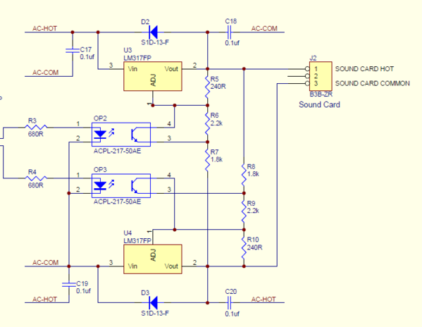
The current for the sound module has to pass through the two LM317 regulators on the sound converter, so there could be a sag based on how much current the sound board is drawing.  The two inputs to the opto-couplers are from the processor, one is the bell, the other is the horn, that's what drives the circuit.  I haven't popped a scope on this, but I suspect you may get some distortion of the waveform from the regulator and diode combo that is passing the AC. 

ERR Sound Converter Output Stage

There was a whole thread on this when we were initially discussing it, then Jon Z. whipped it out in a very short time.  I can't seem to find the thread on a search, but it should still be here.

Attachments

Images (1)
  • ERR Sound Converter Output Stage
gunrunnerjohn posted:

The current for the sound module has to pass through the two LM317 regulators on the sound converter, so there could be a sag based on how much current the sound board is drawing.  The two inputs to the opto-couplers are from the processor, one is the bell, the other is the horn, that's what drives the circuit.  I haven't popped a scope on this, but I suspect you may get some distortion of the waveform from the regulator and diode combo that is passing the AC. 

ERR Sound Converter Output Stage

There was a whole thread on this when we were initially discussing it, then Jon Z. whipped it out in a very short time.  I can't seem to find the thread on a search, but it should still be here.

Just worked through the math on this. With no bell/whistle, the circuit limits the output to a peak value of about 22 volts. Actuating the bell or whistle cuts the appropriate peak to about 10.5 volts.

As you point out, you are going to get some distortion because the regulator is working below dropout for most of the AC cycle. Taking the 22 volt peak and adding a estimated 2 volt dropout voltage plus the .6 volt drop on the other side corresponds to an RMS input of about 17 volts before the limiting takes place.

Because the circuit works by limiting the peak voltage, rather than by superimposing a DC signal, there is going to be a lower limit to the voltage at which it functions; below that point there is nothing to clip! Taking the 10.5 volt peak output limit under bell/whistle conditions and adding in the opposing diode drop and dropout voltage corresponds to an input peak of about 13.1, which is the peak of a 9 volt sine wave.

Having said all that, the intent is that the device be used in a command environment, so little of that should matter.

Just sayin'

Steims posted:

...

Stan, you have the scenario right and no that is not a 10 uF bi-polar capacitor in my pocket. 

I will look for one today and then you can tell me where to stick it.  I will try and get the scope on this tonight.  

I didn't realize there were schematics floating around and this has been a topic of previous discussion.  There is another product (no names mentioned to protect the innocent) that inserts DC offset onto incoming AC using a processor.  It does so by chopping the AC signal in time using transistors (rather than chopping the AC signal in amplitude using a voltage regulator as the Sound Converter.  Anyway, a 10uF bi-polar capacitor placed directly across the AC voltage eliminated a similar phenomenon.

So since they are different methods, the 10uF bi-polar cap shows less promise; I figured it was time for a Hail Mary pass.  Anyway, don't run around looking for one if not convenient.  If you have 2 regular caps of similar value...say two 22uF polarized you can place them back-to-back in series and "make" an effective bi-polar cap.

I'm wondering if there is an accidental connection to ground somewhere in the sound card. Seeing that ERR has replaced the Sound Converter, and this problem is previously unreported, I think we might be looking in the wrong place.

As an example, if the "common" input terminal to the sound card were accidentally grounded, the bell and whistle would work normally from the transformer but the bell would not work from the Sound Converter, because the accidental short would bypass the negative limiter. If there were a short from a speaker lead to ground lots of things could happen depending on the topology of the amplifier. 

If I were king, I'd unhook the Sound Converter from the sound card and check for continuity from any point on the sound card to ground. I would be highly suspicious of any continuity at all.

Last edited by PLCProf

Stan, I posted the complete schematics and the code for the Sound Converter in the TMCC Documentation thread, it was released by Lionel under the GNU.  Here's a link to that post: ERR Sound Converter Schematic and Source Code.

This project was actually the one that pushed me over the edge and got me using the PIC instead of using the Arduino.  I realized that I needed really small processors for what I wanted to do at times.

Last edited by gunrunnerjohn

Oh my.   There's terminology I don't understand and schematics I can't read.  What have I done?  I truly appreciate all of the support to address my little problem but hopefully this will help me and others with same or similar issues.

I will check the Sound Board for grounding.  As I remember, the board has no power/common (black red) to it other than from the Sound Converter.  It does have a volume knob, speaker and a chuff switch wired to it.

I do have Fluke Scopemeter in hand I am ready to use it.  I won't be home for a while yet but will update later tonight.

Thanks.

Another idea.  Presumably whatever other background/chuffing sounds play without incident (for example, don't distort) when you pull the rope.  I didn't realize the Sound Board had volume control...so if you turn the volume way down to just audible so as to reduce current draw through the Sound Converter, does the behavior change?  My understanding is the Whistle is the most power-demanding sound in most engines - maybe this affects the AC voltage/offset in some unfriendly manner.

Here's the 'scope pictures under discussion.  It's interesting that the Sound Converter and the transformer do the offsets in a totally different way.  I'm guessing the chopped waveform has something to do with the difficulties here.

Sound Converter Bell

Cab2 Bell

Sound Converter Whistle

Cab2 Whistle Scope

No Whistle or Bell

No Whistle or Bell Signal

Transformer Whistle

Transfomer Whistle

Transformer Bell

Transformer Bell

Attachments

Images (5)
  • Cab2 Bell
  • Cab2 Whistle Scope
  • No Whistle or Bell Signal
  • Transfomer Whistle
  • Transformer Bell

Add Reply

Post

OGR Publishing, Inc., 1310 Eastside Centre Ct, Suite 6, Mountain Home, AR 72653
800-980-OGRR (6477)
www.ogaugerr.com

×
×
×
×
Link copied to your clipboard.
×
×