One of my FT Remote Switches causes a short, your help in resolving this problem will be appreciated. Six of my seven remote switches work fine with auxiliary power, only the seventh remote switch causes a short when other track is connected to it. By itself the seventh switch works fine with auxiliary power without being connect to other track that includes the other six switches. Concurrently the other six switches that are connected to each other through the track linking them and they work fine with auxiliary power, all Switch Controllers light and are functional. However, when the seventh switch is connected to the track and other switches the short occurs; lights on all switches and controllers are out and the transformer’s green light flashes, indicating a short is occurring. What do you suggest I do to correct the short?

Background: I bought all seven FT Remote Switches (O72, O60, & O36) used and they all seemed to work fine when I used track power. However, for various reasons all seven switches to function on the auxiliary power 10 VAC side of my CW80 transformer.

My Procedure: If there is not a change to correct the short in the seventh switch, then maybe an error can be identified in how I supplied auxiliary power to my switches.

  1. Removed the Jumper clip from each switch’s Aux In and Track Jumper.
  2. Wired all the switches to receive power from the CW80’s Red Accessory B terminal post to the AUX IN, and the Black U terminal post (below the Accessory post) is wired to the AUX GND of every switch.
  3. A Lionel Switch Controller was wired to control each switch (green to Thru, black to GND, red to Out, and yellow to RSC Lights).
  4. When not shorted the red Accessory B terminal post and the black U terminal post on the CW80 measures to be 10 VAC and the same voltage is at the AUX IN and the GND IN of each switch.

My apologies if this problem has been posted and resolved already on OGR Form; if so, please direct me to the Post. I’ve search OGR Forum for “FasTrack Remote Switch Problem” and read at least 80 Posts and their Replies, so far I didn’t find a similar problem with a resolution.

Thanks!!!!

Last edited by IcyTrains
Original Post

Replies sorted oldest to newest

Hey Icy,

Check out the attached Lionel bulletin regarding FasTrack switches from a certain production run. It describes this exact problem and the fix.

I hope that's it and the switch works properly. So, don't question your wiring logic, etc. until you check this out. The worst part is taking out the 14 or 16 little screws and not losing them.

Good luck!

Attachments

Hi Carl, That was it! I followed the directions in the bulletin and corrected the wiring in that switch.  Works fine now!

Regarding the CW80 accessory voltage, the info that accompanied the switches provides a range to operate. 10 VAC is within that range. Recently I reviewed a Lionel video that explains how to change the voltage, so I will increase the voltage to the optimum for switches. I'll also check the date code on the CW80. Thanks again!

Moonman posted:

Oh, I almost forgot- did you check the date code on your CW80?  If it has a G, no problem. You can also adjust the ACC output if the 10v seems a little low, as in the switches aren't snappy. If they work ok, no problem.

Yes, it is a G code followed by 6 numbers is stamp into the plastic bottom of my CW80. Following G is 12, I suppose it was manufactured in 2012; I purchased it in 2013 at our hobby shop, our local Lionel dealer. This evening I was enjoying running a train and all 7 switches (hooray!) so much I have not tried to increase the voltage on the accessory side.

I have a 2nd CW80 I'll need to check it's code. This transformer was purchased used;  and I intend to use it on my inter-ovals of track  as a block. It is at  the hobby shop; I'll explain why in another post.

Moonman posted:

Hey Icy,

Check out the attached Lionel bulletin regarding FasTrack switches from a certain production run. It describes this exact problem and the fix.

I hope that's it and the switch works properly. So, don't question your wiring logic, etc. until you check this out. The worst part is taking out the 14 or 16 little screws and not losing them.

Good luck!

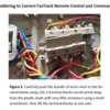
SUPPLEMENT TO THE BULLETIN - I found a shortcut to supplement the bulletin! Instead of unsoldering and re-soldering the wires to the correct terminal blocks. This would be useful for others who may hesitate on soldering in the confines of the switch and near plastic. The terminal blocks can be lifted as a unit, disassembled from each other like puzzle pieces, then reassemble according to Steps 2-4 of the bulletin in the correct order and replaced in the switch. Actually I did need to unsolder and re-solder to create a little slack for the jumper wire, I just moved the other end of the wire to the same piece just closer to the terminal blocks.

Solderless_Correction_For_FasTrack_Terminal_Blocks

Thanks again Carl for providing the bulletin. 

Attachments

Images (1)
  • Solderless_Correction_For_FasTrack_Terminal_Blocks

Add Reply

Post

OGR Publishing, Inc., 1310 Eastside Centre Ct, Suite 6, Mountain Home, AR 72653
800-980-OGRR (6477)
www.ogaugerr.com

×
×
×
×
Link copied to your clipboard.
×
×