Originally Posted by rrman:
Originally Posted by Dale H:
Each ITAD has SPDT contacts. The gates are always powered. Wire them so that the down is in parallel so that either relay will put it down but that the up is in series,where both relays have to be off to power the gates up.
Dale H
Problem is I don't see how to series wire the up line, and yet paralell the down lines with SPDT contacts. Or am I missing something. I posted what I think is a possible solution.
Hi Sam
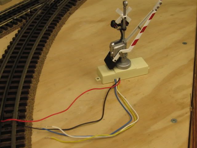
I run mine not using the blue wire as that was the direction on the pack I had. However I will use all 5 as explained in the below post by Mike CT. Blue and white down,blue and yellow up. red and black gate power. First I assume the ITADs have 2 circuits,1 for the relay coils, and another leaving 2 SPDT sets of contacts unencumbered.I assume the coil circuits work properly either connected to track power or to a separate source..
Red and black to the power source, whatever used AC current so polarity should not matter.
As for the contact sets
relay has 1 common, NC and NO.
Relay 2 has common, NC,NO
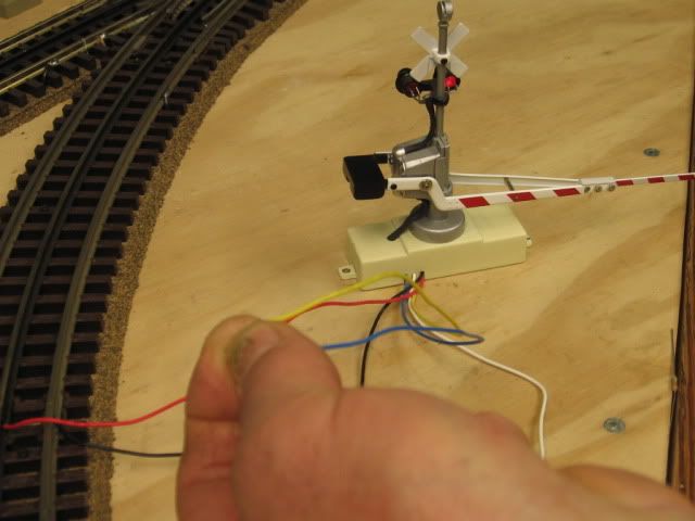
Blue wire goes to common of relay 1
A jumper wire goes from NC of relay 1 to the common of relay 2
Yellow wire goes to the NC of relay 2
If both relay coils are off the blue and yellow wires are connected, If either relay 1 or 2 or both are energized,they are disconnected.
White wire goes to the NO of relay 1 and also relay 2
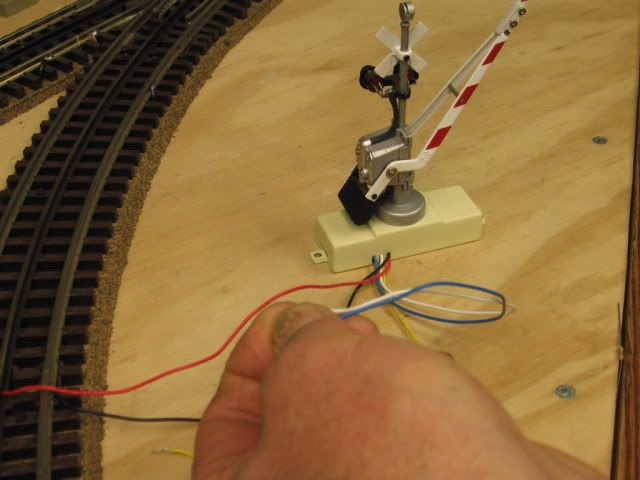
If relay 1 only is down blue and white are connected
If relay 2 only is down blue and white are connected
If both relay 1 and relay 2 are down blue and white are connected
Please trace this on a piece of paper,I think it works. Right now I do not have access to a pen and paper..
I also went to the MTH site,they list 2 ITADs. Both have 5 terminal screws,I think. Why they would tie the commons,relay-coil circuit together is incomprehensible to me. Easy way to find out is with a meter.
Dale H