But I'm a bit fuzzy on the effects of a double header with a heavy load pulling, say, 4 amps of current through the battery. I know all batteries have an internal resistance, and I assume if you are pushing/pulling 4 amps through that D cell, there might be (heat) consequences. Most of the time the duration is quite short, so noticeable effects aren't obvious.
So can you do the same with a hefty wall wart? I have a couple of old laptop charger/supplies capable of delivering 4.5 amps - not that the bell circuit needs that much oomph, but rather it would probably have a fairly low internal resistance.
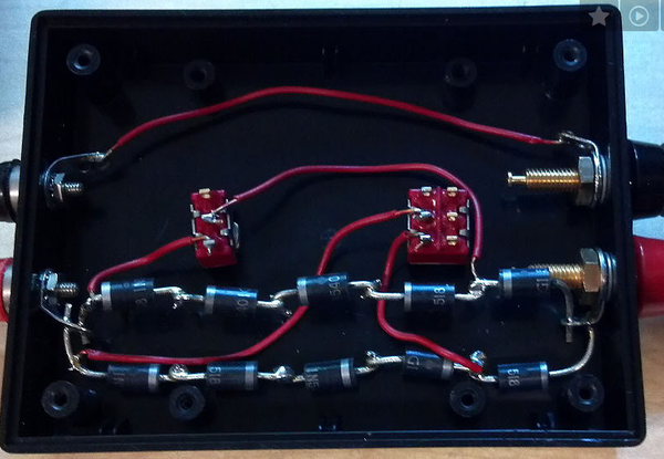
Why couldn't you add an adjustable 3 terminal regulator to regulate the output of a laptop supply down to a couple of volts and switch that in and out of the AC output from a ZW to drive the bell circuit? Fireworks?
The issue with using any DC power supply, battery or wall wart or what have you, is that, when placed in series with the AC track voltage, current will be forced backwards through the DC supply during half cycles when the button is depressed. Depending on the design of the power supply it might be damaged or it might just not work.
Lionel indeed made a whistle control that put batteries in series with the track, I think it was the 147. Worked fine, but the switch in that unit was flimsier than flimsy.
Someone will warn of the danger of catastrophic explosion if you put current backward through an alkaline D cell. I am sure that can happen if you continue it long enough, but I seriously doubt any ill effects in the normal short, intermittent use that a bell button gets.
Nevertheless, I did some research today and found that Eveready still makes the old Carbon-Zinc cells for which the Lionel 147 was designed. They are called "Super Heavy Duty," and they were on the shelf in my grocery store. The data sheet has no warning about explosion; it does say that trying to recharge them (which is what a reverse current does) may result in leakage. When I was a kid, you could buy ersatz battery chargers for carbon-zinc cells, they sorta worked, but the batteries grew weaker with each recharge.
I personally would have no reservation about trying/using the carbon-zinc cells in this application if that is your plan; as you point out it works, is inexpensive and is easily understood.


")
")
")
")
")
")


")
")
")
")
")
")
