It looks like I've misunderstood the purpose.
I know yours works with an insulated rail, but to put this in Lionel contactor terms, it seems like your device would be a substitute for a 145C contactor where the passing train completes a circuit (e.g., to activate a gateman). This would be versus a 153C contactor where the passing train either interrupts a circuit and/or diverts the current from one circuit to another (e.g., from the green bulb to the red bulb on a 153 signal).
Or am I completely misunderstanding and your device can do both?
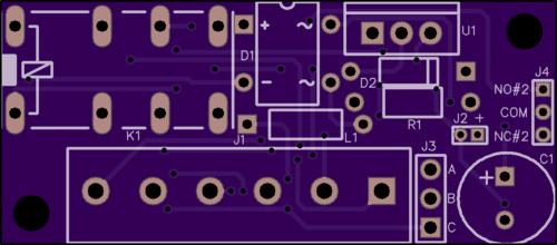
It will certainly replace the 153C contactor, it has both a normally-open and normally-closed set of contacts. In point of fact, there is actually another set of contact on the board to a second header so you get even more functionality. Also, there is a jumper option to allow you to apply either power or ground to the center common contact, or you can isolate it and connect your own. It more than replaces the 153C.
Well, as long as you didn't choke on the regulator idea.....
I didn't work the math all the way through, but if you were to use a 6 volt relay and 6 volt regulator, or a 5 volt pair, you would have a truly universal design that would work on 6 - 24 vac, both conventional and command. You would need to go bigger than a TO-92 regulator to handle the dissipation at the higher end of the voltage range. I would expect a TO-220 package would handle it without a heatsink, you need about 1 W rating for continuous operation of a 6 volt 180 ohm relay with 24 VAC in.
How does this look? I took it a step farther. Since I already have the components for the first run, I left the TO-92 regulator in place, but I put a TO220 regulator in parallel with it. I can use either one, so if I find the 5V relays, I can drop them in, all other functionality remains the same. The only thing that changes is the regulator and the rating on the relay coil.


Looks good, but I found an envelope with a clean back, so I did some more figuring.
Because the load current on the regulator is fixed, we can cheat a little. Keep the 6 volt TO-92, but shunt it with a 910 ohm 1 watt resistor.
6 volt 180 ohm coil draws 33 mA. Because the voltage is fixed the current is fixed.
Let's say the DC supply is worst case 36 VDC, the voltage across the regulator and resistor will be 30 volts, but 30/910 = about 32 mA, so the resistor will handle almost all the current, the regulator will do nothing, hence, no dissipation. Resistor will dissipate about 1 watt
At say 24 VDC, the drop across the regulator and resistor will be 18 VDC, so the resistor will pass about 20 ma, the regulator will make up the 13 mA difference and dissipate about 230 mW.
Worst case will be at 21 VDC, the regulator dissipation will be about 250 mW at that point.
This all assumes that resistors are less expensive than regulators.
Or so the henscratch sez.....