In the first iteration of this post (https://ogrforum.ogaugerr.com/t...from-the-pros?page=1) I requested and received excellent advice.  I started this new thread/post because the space available to me in my basement really doubled (after fixing some flood water damage) and thus it's like a whole new layout.  


With design help from several individuals (Moonman and especially Todd S. who shared MANY iterations of an rrt plan with me) I have been able to achieve many of my original goals for the layout which were:

*  run at least 2 trains on separate main lines, *  sidings to park trains,  *  capability to reverse both mainlines, *   yard for storage, *  track to run some switching ops or puzzle.  I'll put in a short video that actually shows 3 trains running at once.


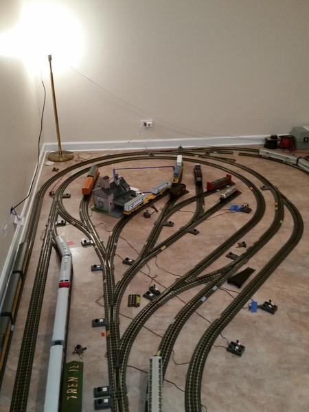
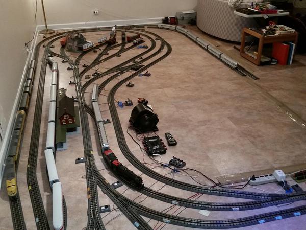
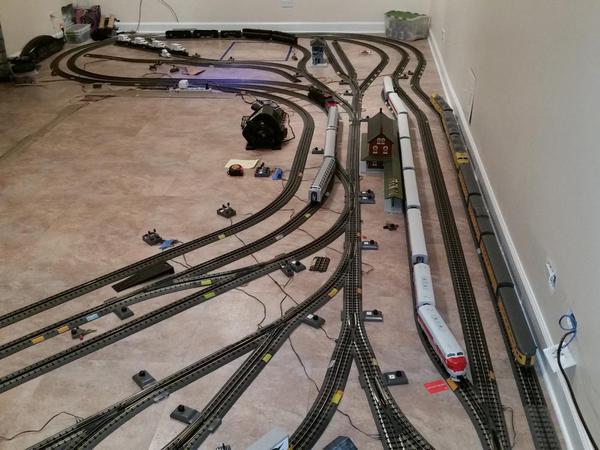
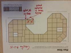
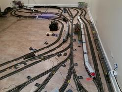
Right now, I'm looking for some help/suggestions re switching operation possibilities in the dogbone ends (South dogbone area especially).  Most of the rrt's until recently have shown a turntable in that area but I don't see having $1500 available for one of those any time soon.  So. I've been playing with different track arrangements around the access openings which are now fixed in size and location (because I will use Mianne benchwork and that layout is set.)  Any suggestions here would be appreciated.  I'll include a few photos of where things stand as of today (not exactly as either of the attached rrts are drawn). 


The photos show that I took out some of the yard tracks (shown on the rrts) to facilitate moving around the layout; the length and number of the yard tracks will be determined to some extent after and as I see how the room looks and feels when the bench work starts to go up.


2 other questions:  does anyone see any need for any other connection between outer and inner main lines and if so, where?  Any tricks I should know about for turnouts in the type of "yard" I'm contemplating for this layout?  Oh, and has anyone ever seen any kind of a lazy susan adapted for use as a round table for manual turning of locos??


Thanks to all for considering the above questions.


north end portrait

north end

south end ls

south end portrait

view to north

view to south

r6 Curtin with cut off yard [56)

Revised Curtin plan view

Attachments

Original Post

Replies sorted oldest to newest

Abuel, Home Depot OR Lowes has precut round  circles and layzy susan devices so you can make your own custom turntable. It sure looks like you are cramming too many switches in your dog-legs, I would get rid of some,looks like you are cramming too much into a small layout. On the right side I would get rid of the switching tracks-too many and no where for buildings. Mike

here's r6 with an Atlas turntable and Roundhouse. Next to it is diesel fueling, sanding  water, and a fuel tank. Moved the hatch a little and made those spurs steamer service with a water tank, water standpipe and room for a coal tower.


use the RealTrack to O adapter track to and from the TT whiskers.


It the spur close to the room could fit a single diesel shed.


Added a switch\yard tower.


3D'd the furniture. I don't know how to get the table (base poly) to 30", s0 it's on the floor. LOL.


I saw a vendor with the Atlas TT in stock. No hole, easy hookup, works mostly ok.


The spurs in the other loop could be reduce to one or two to have a business to deliver goods. or eliminate them for a small town or suburban neighborhood to some more scenery on the layout. It has a high percentage of track, so that would help the overlook look and appeal.

Attachments

Nice job guys helping him out!

Moonman or anyone, any way I can get some design help with a simpler more beginner layout?  My twin boys and I like to run three trains. I have 2) 4x8 Tables layed out as an L, 12' x 8' x 4' I have a bunch of tubular rail 027 and 034, also some older 042 curves, many 027 switches, and a couple crossovers. (don't really like the 027, the 034 is better for the trains) I currently can't really afford to buy all new gargraves or ross track and switches like I'd like to, but I realize I may need to at least get a few of the ross tinplate ones to get mainlines closer etc..Just want to make it fun! so we can start working on making it look good.  I've looked at a lot of layout plans but haven't really hit on the right one, my 6-year old sons thank you for any assistance in advance!!

THX

Dave

Attachments

Images (2)
  • 1
  • 2

Hello all--finally some progress to report and with that new questions arise.

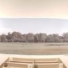
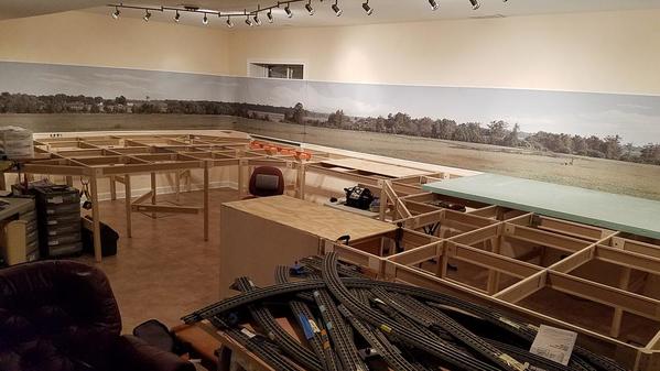
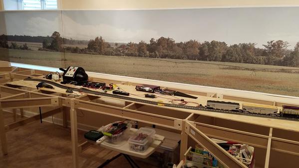
I used a nifty adapter to change the recessed ceiling light can fixtures so that any fixture could be attached and I chose  6-lamp fixtures which permit me to direct illumination wherever I want it--on walls (backdrops) or the layout.  The backgrounds are from BackDrop Warehouse.  I had many feet of wall to cover so I picked these particular agricultural scenes because it was the only one which had 5 segments (A to E) available in sizes up to 12 feet long so I could get a continuous scene across the 4 walls (or segments of wall) that surround and border on the layout benchwork.  (Panorama shot attached)

(Mounting the backgrounds is a whole other story for another day--all I can say is that a self-leveling cross line laser was a huge help.)

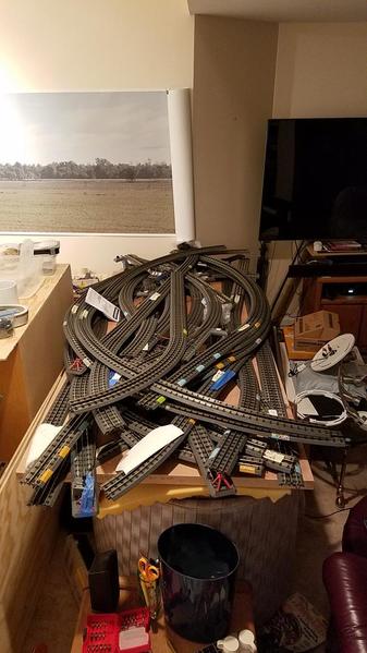
Next I've been working the past few evenings getting the Mianne benchwork assembled (photos and drawings attached).  Which means I'll soon start wiring before any plywood or styrofoam goes on top of the bench work.

To reiterate:  the layout was designed in RR-track, uses MTH RealTrax and I'll be wiring for their DCS system.  I actually assembled the whole layout (or 90% of it) on the basement floor last winter and wired it up using a terminal strip which fed several MTH power lockons.  Interestingly, even though this "resembled" a star or homerun scheme I never actually isolated any of the track segments from one another.  (Track power supplied the many switches).  The video, seen in one of my earlier posts in this thread, actually shows that I got 3 trains running at once.

Well, I'm really a novice at this wiring part (as you can see, I didn't and don't know the best way to isolate segments of RealTrax track).  I've read in the DCS O Gauge Companion that a star wiring scheme is recommended and I'm beginning to understand the reasons.

SO my questions:

1.  Could someone who has wired something similar to my layout perhaps describe in words (or markup the RR layout plan) to indicate where to breakup the track into segments (? every ten feet or so?).  I know that I should probably have the two long passing sidings be isolated so I can park a train there and not keep it running.  Similarly, I assume one would do the same for the yard that I have.

2.  When I did the trial layout on the floor, I used track power for the switches--as you can see, there are a lot of them!  However, should those now be powered from the 10 or 14 volt output (which?) of my Z-4000 transformer?  Should each switch be wired back to a terminal strip as well?  I have one AIU but I don't think it can handle 20+ switches.  Moreover, I think at least at the outset, I would just find a location near the middle of the layout, where I could set up in a bank all the MTH switch controllers so I could route the trains manually--or maybe two banks, one for the left half of the layout and one for the right half. 

3.  I'll have 3/8" plywood and 2" styrofoam over the benchwork.  Any tips on making the holes to thread the wires from the switches and the power lock-ons to the under side of the layout and thence on to the terminal strip?  Drill and then use a large straw??  The Miane bench work cross members beams do have small holes every foot or so depending on the length of the beam--the part of the beam that has the holes is Masonite so I think any of the holes could easily be enlarged from their present size of 7 and 4 mm. respectively.

4. 4.  Thanks to Carl (Moonman) for the RRT and the ideas about buildings--as I get to re-laying the track on the actual benchwork and not the floor, I'll incorporate those ideas.

5.  If someone were to mark-up an RRT with wiring suggestions, either my R7 version or Moonman's R6 variant would work.

Many thanks for reviewing the current progress and considering my questions.


20160914_16595420160914_18325120160911_193615

Attachments

Images (3)
  • 20160914_165954: shows where I thought I might locate the transformer
  • 20160911_193615: panorama shot
  • 20160914_183251: the RealTrax track sections piled up waiting to be relaid on the benchwork but wiring is yet to be done as well as cut and mount all the plywood and styrofoam.

Hi,

Good to hear from. The train room area looks great.

Some cut the center rail connectors to isolate the blocks. I flattened them on the museum layout and placed 3M Professional Electric tape (Home Depot, Lowes)over it to isolate the center rail. I would say about every 12-15 track sections would work.

I use a piece of coat hanger or 10 or 12 gauge wire for a fish and masking tape to hold the wire. Get a long drill bit or speed bore for the holes. 5/16" or 3/8". messing with small holes stinks.

Plan the wiring now and pull as much as you can before you put the deck on. You'll need to decide if you want holes in the cross pieces for wire feeds or if you want to attach the wires later.

I'll mark up the plan later. I have some stuff to do. How many terminal boards do you have? Which number of terminals?

Definitely decide where you want the transformer. Which viewpoint did you like the best when it was on the floor? I would consider the end near the people area. You won't have to turn your head to see the whole layout when trains are running. Visitors will be able to be inside without blocking your view.

Talk to you later.

Abuelo,

I marked up the layout plan that I had. Just make the inside tracks one DCS block instead of the roundhouse. Keep in mind that these are DCS blocks. On the sidings that you want to be able to kill power for parking trains, you'll just have to add an isolation joint. The siding near the big station is already marked that way. The sidings near the people end, desk side, (north end) are marked that way also. The others you'll have to decide.

It looks like two terminal boards, located on each end near the center should do it. The 12 position should be good. 3 if you use accessory power for the switches.

The track connections should be at the end of a block and then repeat the pattern in a clock-wise or counter-clockwise direction. Don't place two next to one another.

You'll need a Z-1000 brick if you want to power the switches separately. Use the fixed 14VAC out terminals. Don't use the ACC from the Z-4000. Most will say do it, but if you had no issues with track power on the floor mock-up, I see no problem using track power. I watched the video as the trains ran around and didn't see any flickers on the switch motor lights when a train passed or in the car lights.

it may also be a good idea to get a Z-500 brick to power the TIU.

This view to south photo is an example of why I suggest operating from this end. No head turn and the whole layout can be seen.

view_to_south

I would recommend 14 gauge wire for all of the track power wiring. You can use 4 conductor phone cable (solid 22awg) for the switches if you track power them.

You can only put 10 switches on an AIU. So, you will another or two.  You'll need some toggle or button switches for the siding kill switches.

You'll also need a multi-meter for testing and confirming wiring connections, block isolation and such. Harbor Freight if you don't have one. probe leads and alligator clip jumpers.

Track plan and layout print attached.

Attachments

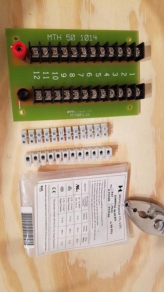
Thanks, Carl for your always thorough and prompt reply.  Been very busy today with grandchild over.  Will study your recommendations in detail tomorrow and over the week-end.  Enclosed are some pix of finished assembly of the sub-structure and of the terminal blocks I have:  1 MTH terminal block and 10 of the white ones.

The cabinet (with plywood on it) attached to the yard end of the Mianne benchwork is an old one I had stored for years and it works just fine and saved me a few $ on Mianne parts.

Will write soon.  Thanks


20160915_23191720160915_23282420160915_232902

Attachments

Images (3)
  • 20160915_231917
  • 20160915_232824
  • 20160915_232902

Ok, now that I see that you have the power table centered, I added the Z-4000 graphic to the rrt file and numbered the connection points for the blocks. The 12 port MTH will work fine for the track power connections. Center that with the TIU centered also. The TIU out to MTH board, MTH terminal board to track connection points.

I actually soldered the power feeds to the end of the track clips underneath on the museum layout to avoid using the lock-ons. We made it a two person job to make it move faster to have hands to hold the wires. I also soldered a jumper wire to connect both outside rails.

Now you should have a map to pull the wires to the approximate locations. yeah, it uses some extra and wastes some, but it's better than spending more time under the layout.

I got an automotive creeper at Harbor Freight to get around under the layout. Use a coupon or look for a nice sale and a coupon. The multi-meter is free this month when you buy another item.

Attachments

Appreciate the additional tips:  today it was hard to work in the basement since it was 85 degrees, sunny and not humid here in the Chicago metro area. 


20160918_20025120160918_20040520160919_170330

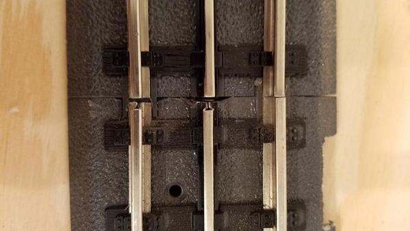
Yesterday I assembled several sections of Realtrax and experimented with getting them isolated.  I flattened all the contacts and then filed down the center rail and one of the other two rails with the Dremel tool so they wouldn't touch the rails of a section piece powered by the other lock-on (pix attached).  It happened to be the outer rail I filed; should I file both of the non-powered rails?  If not, as I go around the layout and back and forth does it have to be the same non-powered rail that I file?

I also powered the turnout from a different output from the track power as I think I want to do this for the layout.  Just for this exercise I went from the 10 volt output of the Z4000.  (The switch manual says it operates on 10 volts and 1.25 amps.)  However, I think in a post above you said not to use the ACC on the Z-4000; is the 10 volt the same as ACC?  I don't see those letters on the back of my Z-4000.  You mentioned using a Z-1000 to power the switches, I think.

I will have over 20 switches.  Should I use additional terminal strips near the Z-4000 or a Z1000 and then send wires from those out to all the switches much as one sends the wires out to each power lock-on?  

Obviously, since I want to "bank" the MTH switch controllers in groupings on a fascia or small shelf at the front of the layout, I will need to lengthen the 3 cables  (green-red-black) that go from the gray lighted controller switch to the turnout itself--do you know what gauge these wires are?

P.S. do you have a website for the museum layout you refer to?  or pictures?
Thanks, Michael


Attachments

Images (3)
  • isolate: flattened connectors and filed rails
  • snapped together: with filed rails and flattened connectors
  • isolation test

Hi,

I was watching the Bears sweat, too, from the Eagles battling them. Ever since the fog game, I don't like it when the Eagles play in Chicago.

First, there's no need to cut an outer rail or isolate  it, unless you have that as recommendation from another source. Only the center rail. That's where the DCS signal travels, on the hot or the center rail. I think you could keep the gap smaller between the rails. A business card should be enough gap. You don't want big gaps messing with center rollers. Test for lack of continuity using the Ohms setting on your meter to confirm isolation.

Secondly, use the 14v ACC terminal on the Z-4000 to power the switches if you are not going to get a Z1000brick. I would create/use a terminal block for the switch power. Makes the wiring easier. Locate it close to wear switch terminal bank is located.

I use solid wire telephone cable, which is 4 conductor, 22 awg. 3 for the switch controllers and one for switch hot power. The switch gets it's common from track outer rails, one reason to not isolate them or cut the track contacts. Cut the sheathing and pull it off long enough to reach the switch power terminals and the switch controllers. Remove the stock cable and save.

The museum is called the InfoAge Science Museum. We are restoring a child's layout for a memorial and an attraction display at the museum. Eagle Scout project.

I hope that helps.

Add Reply

Post
The Track Planning and Layout Design Forum is sponsored by

AN OGR FORUM CHARTER SPONSOR

OGR Publishing, Inc., 1310 Eastside Centre Ct, Suite 6, Mountain Home, AR 72653
800-980-OGRR (6477)
www.ogaugerr.com

×
×
×
×
Link copied to your clipboard.
×
×