
Actually, the Super-Chuffer has it's own 5V supply from track power. Some folks use the Chuff-Generator without the Super-Chuffer, in that case you do need a source of 5VDC.

Hancock52 posted:

GRJ, do you sell these? I think I could do with some!

I have sold a few, but since they're not a production item, I have to hand assemble them, so you can guess that I don't sell a lot of them.   It was one of a number of boards that I really did for my own internal use.

John,

For the older MTH 70 Foot Scale Madison  cars, think the numbers are MT-4005, I want to take out the old lights and add LED's that are DCS friendly. I think at one time you indicated that the cost for the complete 2 car set was $25 or $30. Can you confirm and share a picture of the board and LED's.

 Good to see you at Trainstock.

kevin

Kevin,

The LED Lighting Regulator and the LED strips are all you really need if you don't mind soldering a few wires.  I stick the regulator board up to the ceiling of the passenger car with double-sided foam tape and just wire track power and the LED strip to the four connections on the left.  The MTH cars are really easy, I usually have the lights in far faster than adding the passengers.  I buy the LED reels on eBay.

https://st.hzcdn.com/simgs/c561f0a30268772a_4-1929/contemporary-undercabinet-lighting.jpg

Attachments

Images (1)
  • mceclip0

The output of the LED regulator board is actually constant current, the voltage will vary as required to maintain the regulated current.  This provides a steady unchanging light intensity, the capacitor stops the flicker from intermittent roller connections.  The small pot on the board adjusts the current from around 5ma to around 45ma.  At 45ma, the strip of LEDs in a car are way brighter than most people would want them, so the adjustment range usually works for anyone, no complaints so far.  I have a bunch of little 1" x .5" double-sided foam strips that I bought on eBay that are the perfect size for the lighting modules, that's what comes in the full lighting kits.  You can use pretty much any double-sided foam tape and just cut it to size, most big box building supply stores have plenty of choices.

BWRR posted:

Is the output of your board 12V DC?
So the reel is 12VDC LED's?

Yes, the reel is the bog standard 12V LED reel.  You can use white, warm white, or yellow, depending on the effect you're trying to achieve.

BWRR posted:
Is the power supply in 20100, the same as 20110?

The power module is exactly the same, the kit just includes all the parts you need for a solderless installation.  Obviously, it's considerably cheaper to do a little soldering and just use the regulator modules.

GRJ

To be very clear, no complaints at all.  I am planning on using your LED kits for my passenger cars, but am thinking of using the LEDs in some other uses and trying to figure the Electrical part.

So the LED's supplied in the kits are 12V correct?

What does bog standard mean?

What color are they?  I have a kit, can I tell by looking at them?

I was thinking that if I have a couple of smaller cars, caboose for instance I could buy a lighting kit, and a couple extra power supplies.  That I could shorten one of the LED strips from the kit, then use it with an extra power supply.  This works, correct?

Finally if you would not mind a little electrical lesson.  Part of what brought me back to the hobby is I am very interested in learning about the electrical workings of things.  I am a electronics packing guy (so mechanical professionally), I can solder and all that, but never had an opportunity to understand well enough to figure it out myself the electrical bits.  Trains are good for this, they are fun, I understand the very basics of how the motors & simple electric things work, however the command & LED stuff adds just the right complexity for me to be able to learn some.  Finally if I smoke one learning, it is only a toy in the end.

I thought that LED's were purchased by voltage.  I think that LED's are usually 3V devices, when you buy for instance 12V, they are 3V LED's with resistors added.

Is this wrong and they are current devices?  Is there a simple way to explain this relation ship? 

Or maybe I just understand it all wrong

First off, LED's are current mode devices.  They have a typical operating voltage for maximum rated output, for the LED's on the strips, that is almost always 20ma maximum.  Here's a chart that shows the relationship of voltage to current on a typical white LED.  Notice that at 2.8 volts there is no current (and no light), and when you reach 3.3 volts you are at maximum rated current of 20ma.  At just .1 volts more at 3.4 volts, you're already at twice the rated current for the LED!  Note that by the time you get to 3.6 volts you're at triple the rated current, it rises very quickly.  This is the reason that using constant voltage control is more touchy than using constant current.  With constant current control, you can simply set the current at what you'd like for the light level desired and let the voltage take care of itself.  I could have designed the LED lighting controllers to do either method, but IMO using constant current is a much better method for this application, and it also allows a much finer adjustment of the intensity with a single turn adjustment pot.

The two lines on the chart are for white or blue LED's, they have similar characteristics.  Red, yellow, and green LED's would have a similar curve, but at lower voltages.

"Bog Standard" is my term for the generic 20ma LED, the vast majority of LEDs you see used in model trains will be the 20ma versions.  There are lower and higher current models, but they're far less common.

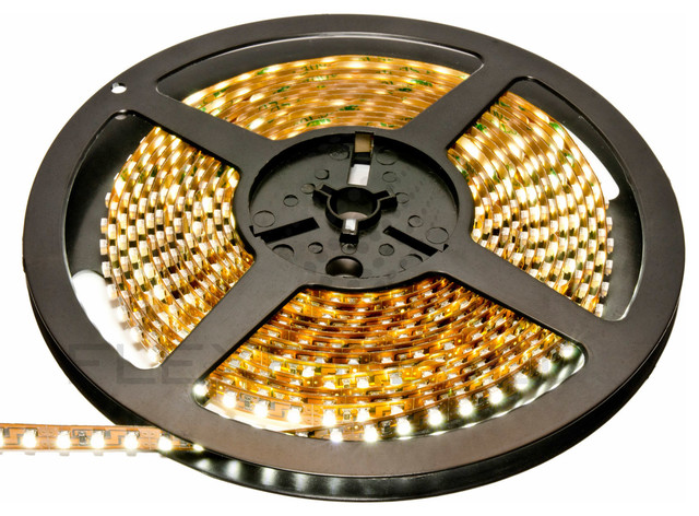
The LED strips in the kits are the strips that are rated at 12VDC, that's the typical operating voltage.  At that voltage, most of the full 5 meter strips are drawing about 1.5 to 1.7 amps, somewhat short of their maximum rating of 2.0 amps for 100 sets of three LED's in series/parallel connection with 150 ohm resistors for each set of 3.

The resistor is what limits the current when you buy a plain LED and want to connect it to a higher voltage.  A simple rule of thumb is for every volt you want to drop for a 20ma LED, you need 50 ohms.  So, if I had 12 VDC and wanted to power one 3V white LED, I'd need a 450 ohm resistor for full intensity and the full 20ma rated current.  Since the 470 ohm standard value resistor is only slightly higher, it's typically the choice for that use.  You can always use more than 50 ohms/volt for current limiting and have reduced light output, but you should not use less than 50 ohms/volt for a 20ma LED, they die pretty quickly with excess current.

I hope that answers your question.

oh perfect, a clear answer that just confuses me even more.  I actually did laugh right out loud at myself.  For some reason I am really struggling to grasp what must be a simple answer.

Let me see if I understand what you mean.

The LED is a voltage device, so for instance the 3V LED should run at 3Volts.  This is a problem to set however because the total circuit (including the LED) has to obey ohms law V=IR, and small changes in voltage make big changes in current.  So to get the 3V it is better to control and vary the current.  I am guessing this is the case becasue while the LED is a voltage device, it fails due to over current.

Is this correct?

Wow, maybe I even sort of have it.  The combination of CJACK, giving me an answer which made me think, then the detail that GRJ added is pretty cool.  

I believe that GRJ, has confirmed my understanding of the LED.  I think I understand enough to feel satisfied for at least a while.

Thank you VERY much for your patience and willingness to teach.


I do have a couple more GRJ lighting module/PS specific questions.

What color are the lights supplied in the kit, warm or bright white?

The power supply in the kit is constant current.  Does this mean that if I reduce the number of LED it is driving by shortening the length, it still delivers the same current?  Or is it once there is a load, and the pot is set, the current is constant?

Or for instance if I wanted to add a RED LED to the back of a passenger car, can I add it and the power supply still delivers the same current?  If I were to do this, would I need to add a resistor to this one LED?

The LED's I supply with the kits are all warm white.  They're the most commonly requested, and trying to have multiple colors really complicates a low volume operation like mine.   If you really want bright white or yellow, I suggest the regulator modules and just buying the reels of LED's.  For instance, I'm using red in a couple of the Hogwart's cars.

If you want marker lights or drumhead LEDs on your passenger cars, you can indeed add those.  What I do is string them in series, then adjust the resistance in series to get the proper intensity balance between them and the strip lighting.  It's somewhat of a balancing act as you'd probably either be using different color LED's and/or different numbers of LED's, so the resistor value is not a fixed and known quantity.  For a single red LED, for instance, I've used a 2K resistor in series, that gives me about 5ma through the single LED and lights it plenty bright enough for the rear facing LED on the observation cars.

OK, that is exactly what I am thinking of doing.  So what I am doing by changing the resistor is changing the current thru that one part of the circuit?

When you hook to the power supply do you connect the lighting from the strip, and the circuit which has the extra lighting in parallel? 

How do you get all of these currents while you are working, measure it or are you really just looking at the LED then back calculating the current? 

Yes, the resistor is changing the balance of currents to the coach light strip and the markers. 

So, let's say for example, if I have the regulator set to supply 30ma, I'm going to share it between the LED strip LED's and the markers.  Given that scenario, I probably want the lion's share of the current to go to light the coach.  I would probably select a resistor in the 1500-2500 ohm range for the markers.

As far as how I do it, I'm doing it by experience.  However, when I'm picking the resistor for a new configuration, I just try a couple with a temporary connection until I like the intensity.  It usually ends up being only a few milliamps to the markers or rear warning light.  I keep a stock of resistors of various values so that I have the flexibility to select the proper one for the light levels I'd like to achieve.

If you want an assortment of resistors for tasks like this, I'd start here at Digikey 1/4W 5% Resistors Qty 25 Each Value.  To start, I'd consider an assortment something like this.

47, 100, 150, 220, 330, 470, 680, 1000, 1200, 1500, and 2000 ohms.  Those are a decent range of useful values for most lighting needs.  The whole list will set you back less than $10 + $4 shipping for 25 each.

OK great.

When I would try and figure out what to use, I should start with a high value and work down, correct?  I think if I were to start to high, it would just not light, but if I start to low it would burn up the LED.  am I understanding this correctly?

Also, since I am doing an order any way, I notice for other applications you often suggest adding a diode to "protect the LED" from the backwards part of the AC.  Which of these would be good to have as generally good for this?

I notice that a cap is nice sometimes to help with flickering.  I was thinking of also ordering some 50v 470microfarad caps.  Sound like a good choice, or would I need various values?

Yes, higher won't hurt anything too low and you risk over current and failure. 

I use 35V caps, they're good for anything you'll encounter running from 18-20 VAC track power, they're a bit smaller and cheaper as a rule.  For a single LED, I use a 100uf cap.  For heavier loads, make the cap larger.  I use a 330uf 35V cap on my lighting modules. 

For diodes, I keep a big bag of 1N4003 diodes around, they're a good general purpose diode that works for most things you need a diode for.  Obviously, for my circuit boards, many of the diodes are surface mount and are selected a bit less generically.  

Another thing I like to keep around in quantity is 22uh RF chokes, they are good to prevent DCS problems if you use capacitors across the track feeds after a diode or bridge rectifier.

I will add all of these, so I have them for messing with.

Is there a product that is good for making little circuits on?  I remember the guys used to use something I think was called perf board, but I may be mistaken.  What I am looking for is a way o have some thru hole things neatly held in place.  You must use something for breadboarding? 

I think at least for now I am going to stay away from SMT stuff at least for now.  My SnPb skills are more with larger things and thru hole. 


GRJ,

What current rating chokes do you stock and out of those which do you use the most of? I presume there are a few different ones? Also, are there any other specs for the 22uh chokes that need to be considered?

Any way to tell what the current rating is on some you already have? I got some on ebay quite a while ago and I don't know what the current rating is. (Not that I know what I am doing now, but that was back when I knew even less .) 

BWRR posted:

Is there a product that is good for making little circuits on?  

Just do an eBay search for Prototyping Board, you'll have lots of choices.

rtr12 posted:

GRJ,

What current rating chokes do you stock and out of those which do you use the most of? I presume there are a few different ones? Also, are there any other specs for the 22uh chokes that need to be considered?

Any way to tell what the current rating is on some you already have? I got some on ebay quite a while ago and I don't know what the current rating is. (Not that I know what I am doing now, but that was back when I knew even less .) 

I use them in the 250ma range for most of my stuff like lighting and low current power supplies.  I have a number of sizes for SMT parts as I use them on a variety of boards.  I also have some 11A ones for isolating yard tracks.  You want to look at the rated current and the saturation current.

There's no easy way to determine the specifications of existing ones with no ID.  You can kinda' guess from the size.

Ok, thanks, GRJ. That helps with what to look for. When I looked at Digikey earlier they had frequency and a few other things in the specs. I wasn't sure what was needed for all the extra choices like that.

Seems like the ones I have are in the mA range somewhere, but I don't know exactly what? I can't find the info I printed out from the ebay seller...or I forgot to print it? 


BWRR,

Just a thought here, and if you are interested? There are also breadboards for fiddling with the circuits before making them permanent on the perf board. You can easily experiment with different things and see what happens with the changes. An ebay search would probably be good for those too. Many times they come with the jumper wires and things you need to start fiddling.

GRJ
Thank you very much for being patient.  I am sure this all seems so simple, but I was just stuck, not really understanding and having so many choices that I could not get started.  Next step for me is to order some parts then make smoke..................er no of course not I will be making little LED circuits, at least for an instant

RTR12
Yes I have stumbled on those, and had even found prototyping boards.  I actually search on "bread board"  I think I got 9254 hits.  I was hoping for a little bit more guidance about what to chose, but I am just going to jump right in.  What I am thinking I will do is buy some resistors and caps, then make up a board with varying resistors so that I can connect the LED easy to each one and see what happens.  I am sure after a few tries it will make much more sense to me.  I am actually very excited to give it a try. I am interested in trying to understand some of this rather than just copy what some one else does. 


Thanks again everybody

I'm not the expert here, but I know of at least two types of prototyping boards. One has no copper traces on it and you use wires to connect things (this may be the 'perf board'?). The others have copper traces. Some of the traces are laid out for certain tasks. I believe they have some that duplicate the bread boards (in the way the holes are connected), in addition to several other types. I know a couple, but there are more than that available. Some have traces to fit IC chips and other things like that.

I think the main differences in the bread boards are size. Here's one that comes with jumper wires and will be more than large enough to get you started and also accommodate larger projects as you learn more. This one came up in a search, but there are tons of them out there to choose from. Included in the search there were also lots of bread boards with a starter pack of parts, like resistors, caps, LEDs, etc. It might pay to do some looking around.

Digikey is one of my favorite places to order and I might just order some things from GRJ's list above for myself. I didn't know about their packs of 25 until looking at GRJ's link. Very good place to order, fast and very reasonable shipping charges using first class USPS. There are also lots of multi-value packs of resistors, caps, etc. available from ebay, Amazon and other places. Digikey probably has better quality parts, but some of the Asian suppliers prices are very low.

I have been fiddling with this stuff for a few years now and am just now starting to get a pretty good supply of parts on hand. It will take a while to build up your supplies. I enjoy the electronics, following GRJ, Stan2004, PLCProf, JGL, and all the other electronics folks around here just as much as I do the trains. There are some very good folks to learn from here! Good luck and have fun.

GRJ,

I have one of those for Arduino. I also have interest in the PIC chips, but there are so many of them!

They also have a PIC Basic programming language, do you have any information about that? I thought they used C, which I don't know? But back in the '80s-early '90s I used Microsoft QuickBasic and Basic PDS to do some stuff. Some we used at work, it was pretty easy. Had an add on library in ASM for the harder stuff.  

The top board in your post looks pretty neat. I would probably the start with the smaller chips, like the 8 pin or something like that, maybe a little bigger. I didn't read the specs on that board, but I have seen some that do several (maybe all?) different PIC chips.

Anyway, I was more curious about the PIC Basic and if that could be used with anything you know of? I will stop pestering right after this...

The Arduino and the PIC family really target different audiences IMO.  While there are PIC based products similar to the Arduino, my interest in the PIC was for embedded processing on custom boards where the size is key. There are a bewildering array of PIC processors with a lot of overlapping capabilities.  I suspect that many in the PIC lineup are there for historical reasons, they were used by enough customers that they simply keep making them.  Most folks that use the PIC will pick a handful of processors and stick to those for their projects.  I've used three or four so far, and I suspect I won't expand that too much without a good reason.

Consider something like the small Arduino boards next to something like my Super-Chuffer.

Similar board area, but totally different characteristics.  For the Super-Chuffer, I picked a chip that had a limited number of I/O pins, but the board also has all of the I/O conditioning and a fairly hefty power supply as well.  With the Arduino board, you have tons of digital I/O pins and the USB interface, but any signal conditioning and power are add-ons. 

I view the PIC family as building blocks for small custom products, and the Arduino boards as building blocks for more plug-together kinds of projects.  Obviously, they have a lot of overlap, but at least in my mind, there is a logical difference that makes the selection fairly easy for me between the two.  I can't visualize trying to use the Arduino for my Super-Chuffer, or for the Chuff-Generator, it's a round peg in a square hole, it just doesn't fit.

Attachments

Images (2)
  • mceclip0
  • mceclip1
rtr12 posted:

GRJ,

I have one of those for Arduino. I also have interest in the PIC chips, but there are so many of them!

They also have a PIC Basic programming language, do you have any information about that? I thought they used C, which I don't know? But back in the '80s-early '90s I used Microsoft QuickBasic and Basic PDS to do some stuff. Some we used at work, it was pretty easy. Had an add on library in ASM for the harder stuff.  

The top board in your post looks pretty neat. I would probably the start with the smaller chips, like the 8 pin or something like that, maybe a little bigger. I didn't read the specs on that board, but I have seen some that do several (maybe all?) different PIC chips.

Anyway, I was more curious about the PIC Basic and if that could be used with anything you know of? I will stop pestering right after this...

Microchip has free PIC development software called MPLAB. Along with that is their version of C called C-Lite that you can also download free.

I'm not really a basic kind of guy, I use the C compiler.  It's their standard compiler, it just doesn't have optimization enabled in free mode.  It actually has three modes, free, low cost, and pro, each have greater levels of optimization of the code.  With the fairly small projects I do with it, I haven't felt any limitations with the free version so far.

 MPLAB® XC Compilers

When you install an MPLAB® XC C compiler, you are installing an unlicensed compiler. This means that you are running under a FREE license and you have access to the minimum amount of code optimization and support. For greater optimization and support, jump to the licensing sites that are listed near the end of the installation. Acquire a regular or evaluation license, and activate the license.

Last edited by gunrunnerjohn

GRJ & Gary E,

Thanks for all the info. I just don't like C, but I guess I may have to work on that part. I've seen the PIC Basic advertised, but I can't seem to find out much about it other than I don't think it's free. Was hoping you or someone here may have tried it. Oh, well, I'll give the MPLAB a try and see what happens.

GRJ, 

Yes, I see where an Arduino would not work for the boards you make. Too big! Which PIC chips do you use, probably more important is what is the 8 pin PIC in your Supper Chuffer? And are there similar ones with more pins, which I am guessing would provide more IOs? I have looked at the PICAXE and thought about trying a few of those, but they seem kind of hard to get. There was a person distributing them here in the US, but I think he died and I'm not sure what is going on with them currently? Anyway I was thinking of starting out small, like the 8 pin chip and then see where that goes from there.

Thanks again for all the info.

There is a free PIC basic, Great Cow BASIC.  I hasten to add, it won't have the polish of the excellent MPLAB-X IDE and all the debug tools.  I'd strongly recommend you really consider giving C a shot, a lot of the tools with MPLAB-X are based on using C.  One of the tricky parts of the PIC is all the variations and setting up the I/O ports.  There is a slick plug-in for MPLAB-X that automates this process and turns it into a GUI exercise.  This makes it much easier than when I did the Super-Chuffer and had to pour through the data sheets to figure out all the bits.

There are literally 100's of PIC processor variations in all sorts of different families.  I recommend the "enhanced midrange" processors in the 12F and 16F families, they have a good mix of capabilities and aren't over the top as far as price.  You shouldn't have to spend much more than a dollar on a processor in the PIC family for the kinds of projects you'd probably be doing.

I use the PIC12F1501 in the Super-Chuffer.  It was picked because it had a number of PWM channels, the timers I needed, etc.  I used the thru-hole version so it could be updated in the field by just replacing the socketed chip.  I use the same part in the Chuff-Generator, but I used the small-outline SMT version because it needed to be low-profile.  That one is programmed on-board using the standard 5-pin debug interface.  Since I didn't need more than six I/O pins, I wanted to stick with the 8-pin parts for size.

I use the PIC16F1825-I/SL on my prototype MP3 sound board, I needed more than six I/O pins.  I use the PIC16F1829_SO for the "deluxe" sound board as I needed even more I/O pins.

Thanks for more info. I downloaded all the programming tools, including the Cow Basic (good name!) and I think I will get a couple of the PIC chips you listed above to fiddle with. That should be enough to get me in trouble for now. I will see what I can (or can't) do with them.  

I gather from your post that when picking a new PIC chip you just go through the data sheets until you find something suitable that does what you want and that's the choice you go with. I think I am still a way off from that part.

Thanks again for the added information. I really appreciate all the help.

Yep, decide what you want to do, then what I/O pins and what functions you'll need.  The number of I/O pins determines the package size. Next you need to know what kind of timers and what functions each I/O pin will need to perform, input, output, special function, etc.  I try to stick with the Enhanced Mid-range Core as they have additional capabilities that I think are worth the few pennies more.

There is a somewhat cryptic MAPS Selection Tool on the Microchip website.  They used to have a nicer way to select features, don't know what happened to that page, but I can't find it anymore.

So for a 35V 100uf cap at digi, I chose this:
http://www.digikey.com/scripts...q=636207071295045030

Seem OK?

When I type in 1N4003 diode I only get hits with more in the part number.  They are a little differnt for instance being 1N4003G or 1N4003-B Does this matter?  I selected this one,
hthttp://www.digikey.com/scripts/DkSearch/dksus.dll?Detail&itemSeq=216994235&uq=636207074581368865tp://www.digikey.com/scripts/DkSearch/dksus.dll?Detail&itemSeq=216994235&uq=636207074581368865
Seem right?  


Finally I went looking for the 22uh 250ma RF chokes, all I am finding is SMT parts.  Is this correct or am I missing something?

Add Reply

Post

OGR Publishing, Inc., 1310 Eastside Centre Ct, Suite 6, Mountain Home, AR 72653
800-980-OGRR (6477)
www.ogaugerr.com

×
×
×
×
Link copied to your clipboard.
×
×