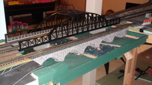
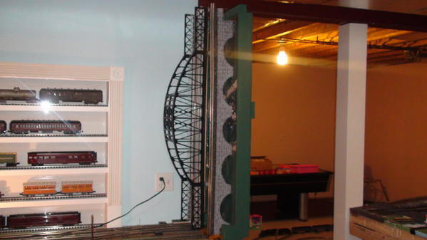
Is there a formula or guide on how long the dead track should be when the lift bridge is open?  I finally got around to wiring up this safety feature tonight.  I have a 36" section of track that dies when the bridge opens.  If I have a train doing 40 SMPH or less, it stops.  If a train is doing 50 SMPH or more before the engine can stop the 1st coach car reaches the dead track and the rear pickup roller on that coach bridges the gap in the rail and electrifies the 36" dead track... so the engine continues to run off the edge.


Thanks for your thoughts.

Ron


Original Post

Replies sorted oldest to newest

Arthur... Of your 3 suggestions, I only really understand your 3rd.


Kill the outside rails, too.

Won't I have the same problem?  The lighting in the coaches uses the outside rail too.


Open the inside rail, and short it to the outside rails, through a 100 Watt light bulb.

 I may need a better understanding of this one.  Maybe a picture or a drawing.
 
Thanks for the thoughts.
Ron


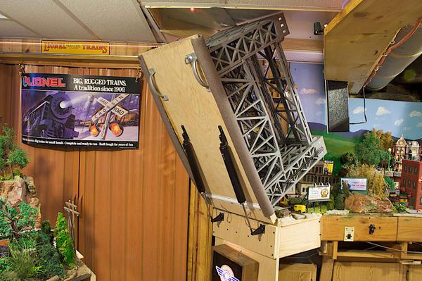
Create a block with your outside rails, the length of you average train size (remember trains go forward and reverse) approaching the open side of the lift bridge section and connect the ground of the rail to a latch on underside of the lift bridge section which then connects thru the other portion of the latch to the ground or outside rails on the lift bridge section. And remember trains can run into the upright portion of the lift section soo you may choose to connect that block thru the outside rails to the latch as well to protect traffic going both ways.In photo note the latch up by the handle its metal an wire is wrapped around the screw holding it in place soldered to rail of bridge.And I operate DCS and Legacy with zero signal issues in setup. Hope I am clear!


liftbr 001


liftbr 002

Attachments

Images (2)
  • liftbr  001
  • liftbr  002
Last edited by dk122trains

Ron, because of your thread, I went to LIONEL's website for a quick read the instructions for the lift bridge--didn't see any mention of the length of the isolated track sections on the bridge approaches which is surprising.  The instructions do say to isolate the center rail.


I went to LIONEL's website also to check the instructions for the LTI bascule bridge of 1997.  Those instructions say to use 4 track sections on each side of the bascule bridge for the isolated track sections; again, isolating the center rail.  HTH.


Last edited by Pingman

This may seem backwards but here goes.... The dead section would have to be long enough to hold the complete pass train. To prevent the power from flowing through the pass car, a relay (controlled from an outside insulated rails prior to the dead section. would keep the dead section "hot" until the train leaves the outside rail insulated section.    The insulated section would only come into play when the bridge is open.  How would you wire  it??? not really sure.  This may be the same as Don's post above.

How would you wire  it??? not really sure.

Currently I have a wire from the center rail of the bridge track soldered to a piece of metal on the bridge.


On the blocked section I have a wire from that center rail soldered to a piece of metal on the end of the bench work.


When the bridge is closed the two pieces of metal are touching and the block is energized.  When the bridge is open, nothing can flow to the center rail.


I selected the center rail just so I would not have to wire this twice by using the two outside rails.


I'm still confused on why some of you recommend isolating the outside rails.  Does it really make a difference of isolating the center rail vs. outside rail?  It seems to me either way you are killing power.   Can anyone explain that to me?


I'm thinking now that we are talking wiring and electricity vs the length of a track block that this is now technically in the wrong forum.


Thanks!

Ron


Originally Posted by Gregg:

This may seem backwards but here goes.... The dead section would have to be long enough to hold the complete pass train. To prevent the power from flowing through the pass car, a relay (controlled from an outside insulated rails prior to the dead section. would keep the dead section "hot" until the train leaves the outside rail insulated section.    The insulated section would only come into play when the bridge is open.  How would you wire  it??? not really sure.  This may be the same as Don's post above.

Greg, the isolated bridge approaches and the bridge track are separately powered using a lock-on (or alternate method).  The controls inside the lift bridge and bascule bridge shuts off power in the isolated track section with the lock-on (and the bridge track and other approach track due to loss of contact by the bridge track to the approach track with the lock-on) when the bridge is lifted, and restores power when the bridge is fully lowered.

Originally Posted by Ron045:

(remember trains go forward and reverse)

Duh... I did not even think of that.  We run some passenger trains backwards.  I need to move that block much further back.  Thank You!


I isolated the center rail.  Why are the outside rails the optimal rails to isolate?


Thanks!

Ron


Ron You can use either inside or outside rail for isolation and follow what I suggested, I use the outside rails because the wheel sets can pass electricity form one outer rail to the other thru the axle and I isolate them both to protect the block, I do not use the block protection setup for the LLC bridges I use, I have active the lighting and sounds only in each one and depend on the latch and outside rail for protection. Also i have found in the command world of DCS which communicates thru the center rail and TMCC/Legacy which communicates thru the outer rail I have had zero signal problems and engines quickly recognize their respective signal quickly. Hope I am clear.

Originally Posted by Ron045:

How would you wire  it??? not really sure.

Currently I have a wire from the center rail of the bridge track soldered to a piece of metal on the bridge.  What piece of metal?  And why do it; it's not mentioned in the bridge's instructions.


On the blocked section I have a wire from that center rail soldered to a piece of metal on the end of the bench work.  Again, why?  No additional wiring is mentioned in the instructions.


When the bridge is closed the two pieces of metal are touching and the block is energized.  When the bridge is open, nothing can flow to the center rail.


I selected the center rail just so I would not have to wire this twice by using the two outside rails.


I'm still confused on why some of you recommend isolating the outside rails.  Does it really make a difference of isolating the center rail vs. outside rail?  It seems to me either way you are killing power.   Can anyone explain that to me?


I'm thinking now that we are talking wiring and electricity vs the length of a track block that this is now technically in the wrong forum.


Thanks!

Ron


I confess that I am utterly confused by the statement in your original post that the slower train can stop without going off the table with the bridge up; but, a train traveling faster won't stop because a lead passenger car spans the center rail connecting the isolated track section and the non-isolated track section.  Wouldn't the slower train also fail to "clear" the non-isolated track approach to the isolated section?


As for isolating the outside rails rather than the center rail, my only response would be that the instructions say to isolate the inside, not the outside, rail.


Question for Ron:  What passenger cars are you using?  I'm not familiar with the wiring of the various mfgr's wiring; but, a PW Lionel passenger car and LIONEL's early '90's cars used separately wired incandescent bulbs.  In other words, such a car could straddle the isolated and non-isolated trackage and one bulb would be lit and the other dark if the isolated section was w/o power. 


Suggestion:  Wire the approach tracks and bridge per LIONEL's instructions that are linked above; and, lengthen the isolated track section if necessary.

Last edited by Pingman
Originally Posted by gunrunnerjohn:

We use a minimum of 4 feet for our modular club layout lift bridge.  I have some relay controls that kills the power to the adjacent sections when the bridge is up.  The size of our modules is either 4 foot or 8 foot, that's the dead track with the bridge is up.


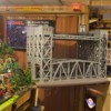
Lift Bridge Closed

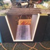
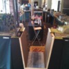
Lift Bridge Open

Nice, that block length works well?


Pictures of the corner modules possible?

Pingman... What Bridge and instructions are you talking about?  We are not on the same page here.  I do not have a Lionel bridge.  I built my own lift bridge and put an MTH Trestle on top of it. 


For my test last night I was using Atlas Comet II cars because they are my longest passenger cars.  The reason the faster train could not stop is because of momentum. 


At 40 SMPH when the engine his the dead block it rolls a little before it comes to a dead stop... long enough for the 1st coach pickup roller to cross into the dead block, which then instantly re-energizes the track and the train continues.  Then the 2nd pickup roller on the 1st passenger car hits the dead block and because the train is going slower, power is cut and the 2nd coach car can not cross into the dead zone.


However at 50 SMPH the train takes a little longer to stop, so there is just enough speed for that 2nd coach pickup roller to hit the dead block, thus again energizing that block and powering the engine again.  That is when it reaches the point where it would run off the table.


So from all I've heard so far, I need to lengthen my dead block at least the length of my longest passenger train running backwards.


I'll try to take a video tonight to show everyone my set up.


Ron


Originally Posted by Lima:
Originally Posted by gunrunnerjohn:

We use a minimum of 4 feet for our modular club layout lift bridge.  I have some relay controls that kills the power to the adjacent sections when the bridge is up.  The size of our modules is either 4 foot or 8 foot, that's the dead track with the bridge is up.


Nice, that block length works well?


Pictures of the corner modules possible?

So far it has worked.  Of course, we also like people to keep an eye on what they're running, so most of the time the power control doesn't really get tested.  The modules that are adjacent aren't necessarily corner modules, they can be any of our modules.  This layout was at the TCA National Convention last year, and the area was pretty narrow, so we ended up going with the narrower setup with just one 4-foot section on the ends.

Ron, apologies for cluttering up your thread with what turns out to be useless/unhelpful posts.  My impression (which is obviously wrong since I'm the only one who made this mistake) is that "lift bridge" is used here in reference to the LIONEL lift bridge, and what you have is a "lift out bridge" meaning one that is physically removed from the layout.


Good luck with finding a satisfactory solution.


Last edited by Pingman
shut Originally Posted by Pingman:

Ron, apologies for cluttering up your thread with what turns out to be useless/unhelpful posts.  My impression (which is obviously wrong since I'm the only one who made this mistake) is that "lift bridge" is used here in reference to the LIONEL lift bridge, and what you have is a "lift out bridge" meaning one that is physically removed from the layout.


Good luck with finding a satisfactory solution.


No No  we need all the help we can get on this one. You're not getting out of here that easily. It's those darn passenger cars with  both rollers  connected to each other  that make this so difficult. The current just keeps flowing through the cars as the engine jerks ahead. It s probably not too healthy for the cars as well or even worse the   engines.  You may have to resort to shut  the whole line down if the bridge is up.   (safety first)

Here we go , no relays , no insulated sections.   The bridge becomes the power supply for the  tracks in either direction. power from the transformer goes to the bridge tracks  (hidden at the hinged end underneath) Each track in both directions would have a plug  that you would have to manually hook up each time you lowered the bridge . The existing feeders would have to be removed.   Pain the butt to hook up??  Yes but it might just save a engine from hitting the floor.. 

The bridge becomes the power supply for the  tracks in either direction.

Ordinarily I'd say that would be the way to go.  We have a larger layout however and a user can open the bridge walk through and close the bridge before a train even get's close.  So we could be shutting down trains a lot for no good reason.


My son and I have this procedure.  Approach the bridge... Look both ways to determine if the bridge can be opened.  Announce, "Bridge Up", then walk through and close the bridge.  Then announce, "Bridge down and secure".


This also warns the operator to pay attention and possibly slow down if they are anywhere close.


Ron

A point about worrying about the passenger cars spanning the gap and keeping the locomotive running.  That's only a problem with DCS, when TMCC/Legacy has a power outage of more than a fraction of a second, they stop until they get another command.  This could be long before a passenger car got up there and spanned the gap in the track.  If DCS gets powered again, even after a couple of seconds, it will take off at it's previous speed again.

Originally Posted by gunrunnerjohn:

A point about worrying about the passenger cars spanning the gap and keeping the locomotive running.  That's only a problem with DCS, when TMCC/Legacy has a power outage of more than a fraction of a second, they stop until they get another command.  This could be long before a passenger car got up there and spanned the gap in the track.  If DCS gets powered again, even after a couple of seconds, it will take off at it's previous speed again.

It still a power surge through the rollers on passenger trains each time. Yes dcs locos carry on with the last command give but in short spurts.    It look bad as well, the lights dim and come on brightly each time a car spans the gap.


 Ron.. As Jon pointed out the bridge protecst the train from the hinged end when it is up.At the other end your pic shows how you fed the center rail.(neat) I'm curious which end of the bridge is the power supply.   Hinged end or pull up end? Are there other feeders at the pull up end?


Ron.. As Jon pointed out the bridge protecst the train from the hinged end when it is up.At the other end your pic shows how you fed the center rail.(neat) I'm curious which end of the bridge is the power supply.   Hinged end or pull up end? Are there other feeders at the pull up end?

There is a power drop at the hinged end.  Then the wire and metal square at the open end powers the dead track (about 36 inches) when the bridge is closed.  In that one pic where you can see the BEEP engine is were the next drop is on the other side of the cut rail.


Ron


 What would happen if you made the dead section longer.  ? You still would have the rollers supplying power problem until the whole train is on the dead section.  (Disconnect a couple of rollers on the head end cars.) You may have to hired a Bridge tender and put a slow order on the track. We have a big Bascule bridge (2 tracks)on our layout that's always up until a train enters the insulated track sections. Then dpwn she goes. One of the insulated sections is about 35 feet. 

Good luck with your project.  Maybe the 110 volt light bulb is the answer , I didn't understand where it would go .

The simplest solution seems to be making sure your cut off section of track is longer than the longest train you plan to run, plus the length needed to stop from speed.  This does have the side effect of having possibly a very long section of track out while the bridge is up, which may not be desired if you are running a different set of cars that do not cause any problems, or if moving slow enough for someone to have the bridge back in place before it would get to the bridge.  


While slightly more complex, my suggestion would be to use an insulated section on either side of the bridge, long enough for your train to coast to a stop from speed,, and use this insulated rail as you would to connect any accessory, only to operate a relay that will cut power to the entire loop of track.  This would let your locomotive continue as normal until it got close to the bridge, then enter a 'danger' mode stopping all traffic.   You would need a contact of some sort on the bridge to keep the relay from being tripped when the bridge is in place.  You could also build a device to simply trigger a halt command if you're running tmcc or such, but that gets beyond the scope of what I would call simple wiring.  


"--What you're doing is a violation of human rights. You can't force men to go out and get killed--when that bridge collapses just to make money for you."


She searched for a sheet of blank paper and handed it to him. "Put it down in writing," she said,"and we'll sign a contract to that effect."


"What contract?"


"That no member of your union will ever be employed to run an engine on the John Galt Line."


"Why . . . wait a minute . . . I haven't said--" . . .
A.S., p. 216-217

I agree with previous posters that the two best options on the electrical side to keep your favorite trains from plunging to the floor due to an open lift bridge are (a) make the dead safety block(s) longer than the longest passenger train with illuminated cars that you plan to run, or (b) totally kill the power to whatever tracks pass over your lift bridge or lift-out section. A mechanical safety feature you may want to consider is a pop-up barrier that would act as a catcher's mitt for any train that might attempt a kamikaze dive off the benchwork. For example, a double layer of drawer liner foam stretched across a rectangular wood/metal frame and sprung at the sides so when the bridge goes up the barrier rises and stops the train if for any reason the safety block fails to do so. I figure folks who've been clever enough to build their own lift bridges should already have an idea of how that barrier would look and work, but if not and you're interested I'll come up with a sketch. 

I greatly appreciate all of the ideas you all have provided.  I did re-visit Susan's Run Room (Where I got the inspiration for the bridge).  Based on her setup and from the recommendation of others, I will have to read up more on relays.  I have little to no knowledge of how they work.


I did some tests last night with a longer dead block.  Here are the results.


Ron


If this is really an issue, it appears that lighted passenger cars are really the primery offender.  Why not simply do a minor mod to the lead passenger car or two?  If you install LED lighting with a decent sized filter cap, you can remove one roller, which stops the issue of bridging the gaps.  You'll still have flicker-free lighting, and you don't need to power half the layout down to open a bridge. 


Another easy mod for passenger cars with LED lighting is to use a low value PTC between the pickups, say a 60-100 milliamp trip model.  If the rollers try to carry the power for the locomotive, the PTC will open within a second or two with that much overload.  Since these are self-resetting, they do this job with no damage, and no intervention on your part to reset.


IMO, you're making this too difficult.


Add Reply

Post

OGR Publishing, Inc., 1310 Eastside Centre Ct, Suite 6, Mountain Home, AR 72653
800-980-OGRR (6477)
www.ogaugerr.com

×
×
×
×
Link copied to your clipboard.
×
×