I am finally starting to use SCARM.  I have the measured outline of my room, 136" x 138" almost a perfect square.  I have practiced making a couple loops of track, and that seems easy to do.  What I have not been able to find is how to draw in my 2 doors and 2 windows on my room perimeter.  I looked over all Mixy's tutorials, but didn't see it.  

I know; it has probably been staring me right in the face, but I need some help seeing it.  Could be my cataracts are giving me more trouble than I thought.    I'm going to stick with that excuse, until I get them removed next year.  

Thank you in advance for helping the blind!!

Last edited by Mark Boyce
Original Post

Replies sorted oldest to newest

Ok then. If you scroll down the list of track libraries, at the bottom you will find one titled "Figures". In there you will see Rectangle, Polygon, Circle, etc. Select Rectangle and then click where you want the window to start and drag how wide & deep you want it to be. On a layout your size, it might help to zoom in where you want the window to go to make sizing and placing it easier. When you get the first window done, you can them highlight it, right-click and select Copy, then Paste, then Move to place it in the next location. For the doors, you do the same thing, but then you highlight it, right-click and select Rotate to get the angle to show which direction the door opens.

Always glad to help and I've had many "duh" moments while learning both SCARM and RR-Track. I'm sure you know that the more you play with this stuff the easier it gets and the more you retain. I hate having to retrain myself after I've been away for awhile. I also learn by looking at the many sample layouts on the SCARM website. In your case, a good sample to review is this one. Even though it's HO and 3D, the basic figures are all there, just with entries for Vertical and Height. You can see he did folding doors. If you really want to make your head swim, check out this one. It's a large N scale and scrolling around the layout is slow. In both cases, many of the figures are grouped, so they have to be Ungrouped in order to look deeper at how they were done. I'm still trying to figure out parts of the last one.

The interesting thing about the 2nd plan is that I can't edit or select anything without first deleting the baseboard or moving it to another layer. If I click anywhere, it always selects the baseboard. From what I see, everything is on the same layer and that's not a good habit to get into. I always use multiple layers; 1 for track, another for tabletop, another for buildings and so on. If I have multiple levels, I use separate layers for each of those elements. That way I can turn the layers on/off depending on what I'm working on.

In this case, I renamed Layer 1 to Baseboard and used cut/paste to move the baseboard to the new layer. Now I can turn it off and select all the other elements in Layer 0 to see how each "group" was assembled. Since you're in the learning stage, it's a good time for you to develop a habit to use different layers. My current layout plan has 4-5 different track designs, all on separate layers.

BTW, how did you define your 136x138 room? Did you define it as a baseboard? A large rectangle? 4 individual lines?

Dave,

Thank you for all the information.  Sorry to take a while to get back to you.  Last evening I did get windows and doors onto my room outline using rectangle figures just as you described.  I was looking at layers.  Right now I just have an outline of the room, windows and doors, and a couple loops of track I was practicing with.  Yes, I agree, I need to learn use the layers.  

On to your questions.

How did I define my room? I don't remember what I selected to draw the outline, but I know it wasn't figures-rectangle.  Last evening, when I selected one side, all 4 highlighted, which makes me think they are not 4 individual lines.  Is that good or bad?  

I got the idea that you use the baseboard to define the edges of the layout.  Other than the room walls, that hasn't been totally determined yet.  I want to get a little more done, before posting, so I don't have to type out a total explanation of my ideas, but let the picture speak 1000 words.  I use the computer all day at work these days, and my eyes and hands are tired and sore once I get home, so design may be a little slow.  

Thank you!

Mark, no need to apologize, I just hope I can help. To that end, here are a few thoughts about Figures and the Baseboard that might help understand how they relate to each other, particularly when designing a complete room and not just a layout.

In this photo, it appears to contain a brown filled rectangle inside a green filed rectangle inside an unfilled rectangle. The unfilled rectangle is made from 4 lines. Please note that there really are no lines in the Figures library, they are made with thin black filled rectangles.

mark01

Now you see what's beneath the green rectangle when Layer 2 is unchecked.

mark02

But wait, now you see what's really beneath all the rectangles when Layer 1 is also unchecked.
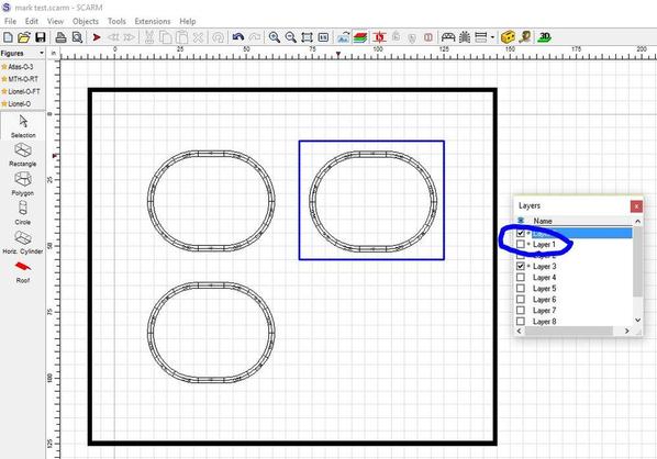
mark03

Now, you may ask yourself why does the track show in one brown rectangle, but not the other in the previous photo. The answer is the Vertical Position for the top rectangle is "6.5" while the Vertical Position for the bottom rectangle is "-6.5". This places the bottom rectangle below the baseboard whose Vertical Position is "0".

mark04

If you change the Vertical Position of the green rectangle to "-51", you can see the other things are now visible (except for the tracks below the upper brown rectangle).
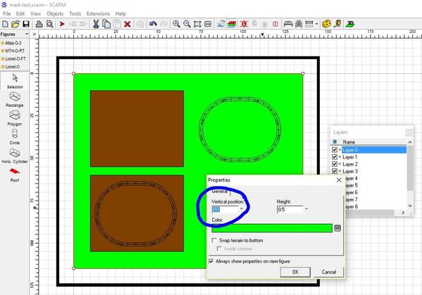
mark05

Now, you might think that you can simply change the Vertical Position of the rectangle to get them to display the way you want, but that's not the case. I changed the Vertical Position of the green rectangle to "12" which should have placed it over the brown rectangle with a Vertical Position of only "6.5". I found that what also comes into play is in what sequence the rectangles were added, the last being on top.

mark06

So, I did a cut&paste of the green rectangle and now it covers everything inside it. Cut&paste is just like adding a new rectangle, so it goes to the top of the display sequence.
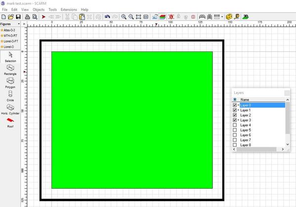
mark07

Unfortunately, it's even more complicated because the rules differ when the rectangle are below the baseboard. This photo shows a green Vertical Position of "-51" and a brown Vertical Position of "-6.5". That should have placed the brown rectangle on top of the green one, but it doesn't. I believe SCARM ignores the "-".
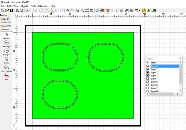
mark08

And lastly, look back at the 2nd photo and note where the blue Baseboard outline is in the upper right. Here's what happens when you try the center the layout in the work space by clicking the "Fit To Window button". SCARM only looks at the Baseboard and anything that extends beyond that gets hidden until you zoom out and center things manually. That's not a criticism, just an observation I noted when I tried creating the room where my layout will go.

mark09

In closing, I apologize for the lengthy post, but it's hard to explain without the photos.

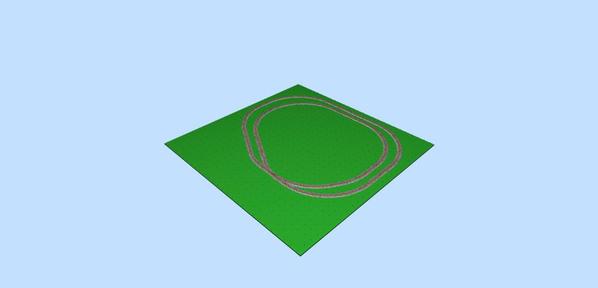
EDIT: I forgot to add the 3D view to show how all these pieces relate to each other.
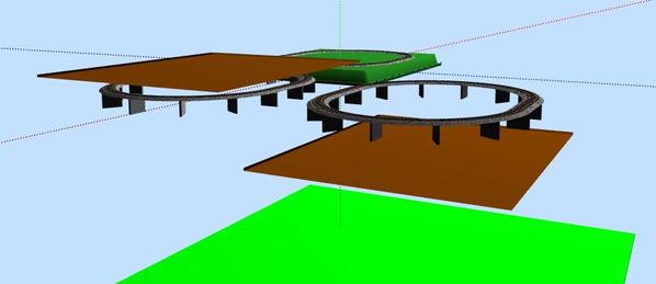
mark10


Attachments

Images (10)
  • mark01
  • mark02
  • mark03
  • mark04
  • mark05
  • mark06
  • mark07
  • mark08
  • mark09
  • mark10
Last edited by DoubleDAZ
Mark Boyce posted:

How did I define my room? I don't remember what I selected to draw the outline, but I know it wasn't figures-rectangle.  Last evening, when I selected one side, all 4 highlighted, which makes me think they are not 4 individual lines.  Is that good or bad?  

I got the idea that you use the baseboard to define the edges of the layout.  Other than the room walls, that hasn't been totally determined yet.  I want to get a little more done, before posting, so I don't have to type out a total explanation of my ideas, but let the picture speak 1000 words.  I use the computer all day at work these days, and my eyes and hands are tired and sore once I get home, so design may be a little slow.  

Thank you!

If you didn't use Figures, then I can only assume you created a baseboard. Does it basically look like these in 2D and 3D? The blue rectangle is a Baseboard and what it looks like in 3D.mark11mark12


Attachments

Images (2)
  • mark11
  • mark12

Dave,

Yes, I think I get it on what shows when certain layers are un/selected.  The difference of what you see when items are at different elevations makes some sense too.  I haven't tried any different elevations yet.

Yes, I made a baseboard of the room, since the 3D view looks like your last image.  

snapshot Draft 1

I will start another one and see what I can do.  Thank you!!

Attachments

Images (1)
  • snapshot Draft 1

Add Reply

Post
The Track Planning and Layout Design Forum is sponsored by

AN OGR FORUM CHARTER SPONSOR

OGR Publishing, Inc., 1310 Eastside Centre Ct, Suite 6, Mountain Home, AR 72653
800-980-OGRR (6477)
www.ogaugerr.com

×
×
×
×
Link copied to your clipboard.
×
×