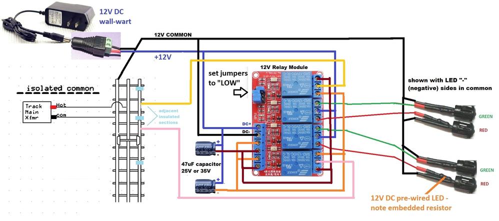
Consolidated Leo posted:

Lets give this a try. The 12 volt common power connects to the outside rail so that the wheels will act as a switch to complete the circuit with the insulated rail sections. The 12 volt power feeds the relay board at DC plus and minus. The 12 volt plus also goes to the COM inputs of relays 2 and 3 which are switched to display either RED or GREEN LEDs. The GREEN connects to the normally closed (NC) outputs and the red to the normally open (NO) outputs. So the aspects will both show GREEN with no relays activated.

A northbound train hits the first insulated rail which connects 12v common (yellow) to the COM input of relay 4 (the one at the bottom). That routes through the NC output (orange) where the capacitor cleans up the signal and activates relays 1 and 3. That changes the southbound aspect to RED but leaves the other GREEN.

When the train hits the second insulated rail, the connection to COM at relay 1 (which is already activated) is routed through the NO connection to the orange trigger input. Relays 1 and 3 stay activated so the signals stay the same. When the first block is vacated, relay 1 continues to hold relay 3 at RED. And when the second block is vacated, the relays all turn off and the aspects return to both GREEN.

The same occurs in the opposite direction. Only the names have changed to protect the innocent. Nicely done, Stan!450 Signal Bridge Circuit

Hi Stan, Just wanted to get your opinion on how far I might want to put the isolated sections from the signal bridge? Just waiting on the capacitors, got the 8 block relay module 2 days ago.

Not sure I understand the question.  Note that the two isolated sections must be close enough to guarantee that both are active as the consist passes thru.  Obviously the simplest way is to have the break between the two sections be just the width of a gap or cut in the rail.  But presumably you want the action to start a good distance (many feet) from the signal bridge (which is presumably centered between the two isolated sections).  So if you only have short insulated sections, then you must insure that any consist is long enough to straddle both insulated sections.

Stated differently.  If we call your two isolated sections 1 and 2, they must be activated as neither, then 1, then 1&2, then 2, then neither.  And going the other direction, they must be activated as neither, then 2, then 2&1, then 1, then neither.

Not sure this answer this is what you're asking though!

Here is what I was thinking, in your wire diagram it shows 3 blue marks as isolated  sections. My thought is that the center one could represent the signal bridge location and the 2 outer ones would be 3 feet on each side. I have no trains that I think I will be running that will be smaller the 6 feet long.

Does this help with my question? Or do you think I should move them in closer together? I really trust your thoughts!

Ahh!  I get your question!

The 3 blue marks in the photo represent gaps in the rail between only 2 isolated sections.  Note how the yellow and pink "wires" are electrically attached between the blue marks suggesting it's the length between the blue marks that is the isolated section.

Perhaps that makes my previous answer more sensible?

stan2004 posted:

Electrically/functionally the length of each isolated section does not matter.  3 foot sections on either side with a tiny gap centered at the signal bridge sounds good to me.  Then you can run, say, just an engine and get your special signaling behavior.

Thanks Stan, Heading to the shop to get wire and get started. Might take a little bit as I go really slow with eletronic's.

mike g. posted:

....Side note, I just got the capacitors in the mail. Is the long end the + or the -?

Seems I missed this question.

Long end is + but if you got these on eBay anything goes and only the shadow knows! 

The sure way to know is it should have a vertical stripe the length of one side of the can with dashes or "-" symbols.  That's obviously the - side.

OK everyone, I got it hooked up correctly on my test track. I want to give big thanks out to everyone who helped. special thanks to Stan2004 for the diagram and arts numbers and a lot more help! John H. for helping figure things out, Elliot for the 2 signal heads, Gunrunnerjohn, Consolidated Leo for telling me we could figure it out.

So here are some crappy pictures and one bad video. but it shows it works!20170302_15450920170302_154834

Attachments

Images (2)
  • 20170302_154509
  • 20170302_154834
Videos (1)
20170302_155433

Thanks RTR, I am so happy it works, when I first started I thought people thought I was crazy. LOL

Yep that's Tank, he is the formen and doesn't like people loafing! so he has to come a check every now and then. He is the reason it took me so long, he kept picking up the signal bridge trying to tell me it doesn't go there!

mike g. posted:

Thanks RTR, I am so happy it works, when I first started I thought people thought I was crazy. LOL

Yep that's Tank, he is the formen and doesn't like people loafing! so he has to come a check every now and then. He is the reason it took me so long, he kept picking up the signal bridge trying to tell me it doesn't go there!

Glad you finally got it placed properly to satisfy the foremen!! He probably knew from experience that it would only work in that one specific spot. Even more satisfying when the foreman is happy and it also works!! 

Add Reply

Post

OGR Publishing, Inc., 1310 Eastside Centre Ct, Suite 6, Mountain Home, AR 72653
800-980-OGRR (6477)
www.ogaugerr.com

×
×
×
×
Link copied to your clipboard.
×
×