
I am looking for a Clear EASY to understand diagram for wiring my Double Signal Bridge by Lionel.

I have (1) Lionel Double Signal Bridge #452

The bridge goes over 2 sets of tracks. Two Independent Tracks running conventional. Two separate trains going in same direction. Two separate transformers Z-1000 and Controllers.
Under the Bridge it has 3 connectors 1) Green Bulb 2) Red Bulb 3) Common

I have (2) sets of Lionel 6-12029 Activator packs that I will install before the Bridge.
I will also extend the length of the tracks by removing the small piece of metal under the tracks to keep the isolated section longer.

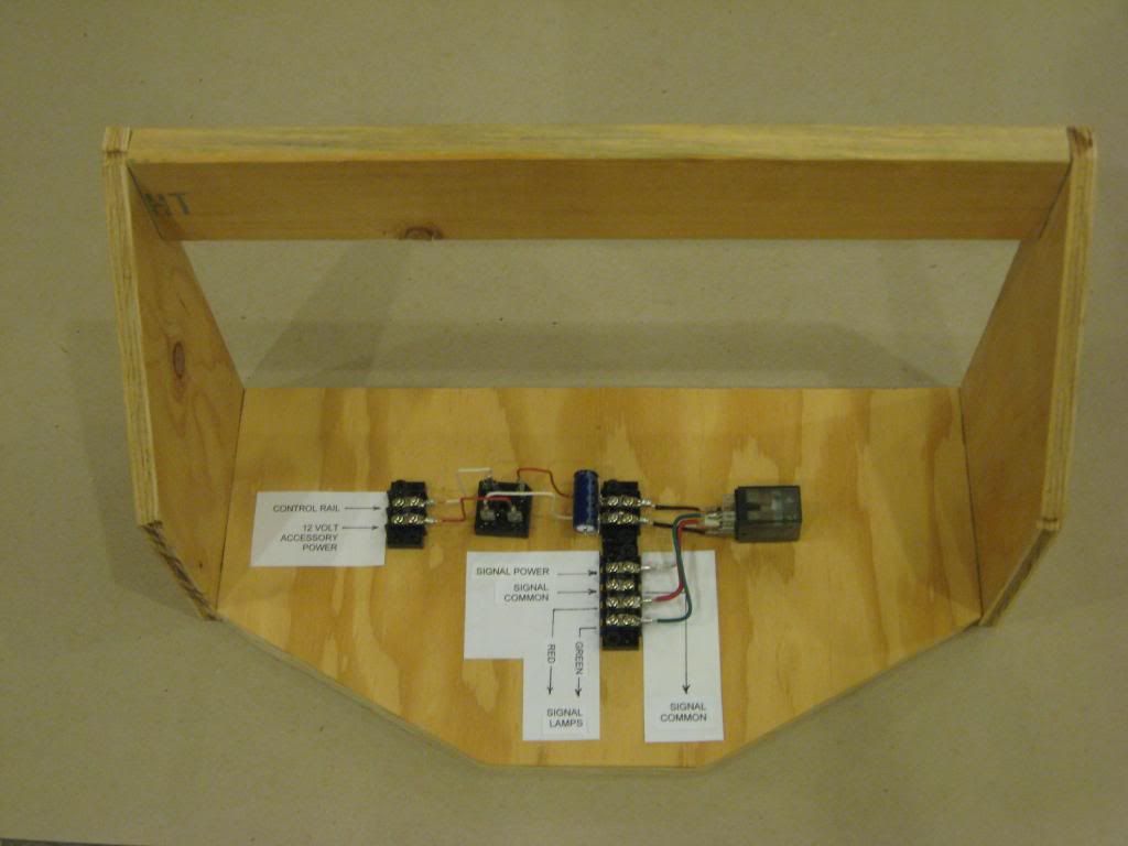
I was told to purchase relays to achieve this so I purchased several SONGLE SRD-12VDC Relays. They each have 3-pins (IN-GND-VCC) and NO-Common-NC Connectors.
Under the relay it says "high level trigger"

I was planning on using the 14V Accessory screws on the Z-1000 for power. I also have several Wall Warts that have 10 and 12V power if I need to use those instead.

What I am looking for is an easy to understand diagram to hook this up so the GREEN Lights are always on and the RED Lights light up when the train is in the Block.

I have a diagram from Dale but it is not clear enough to understand and I DON'T understand fully all the lingo you guys talk about.
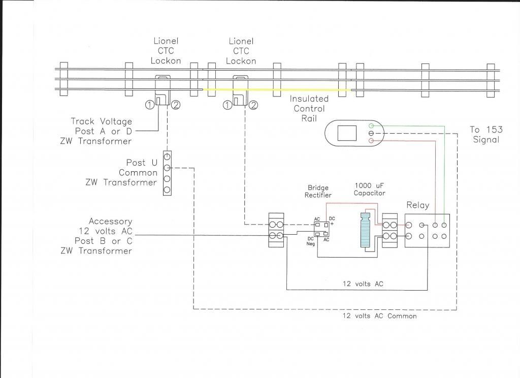
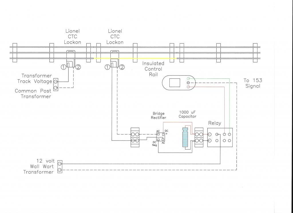
I also have a diagram another forum member sent me but that one uses things like Capacitor and a Bridge rectifier and even that is not clear as to where the wires all go.

I am looking for ":wiring for dummies" kind of diagram.

This wire goes here and that wire goes there etc...

So as always any help is good help.

Thank You in advance


Original Post

Replies sorted oldest to newest

This should work for your 452 signal bridge.  ( 452 same as the 450 ? )

I show a Lionel 153 Block signal, but would be the same for one green/red lamp on the signal bridge.  A second relay set up would be needed for the green/red lamp for other track.  I show the insulated rail as one track length, but you could make the control rail as long as you need for your block.


The following is a list of Radio Shack part numbers that I have used:

Relay  .......................... # 275-0218

Bridge Rectifier ............. # 276-1185

1000 uF Capacitor ........ # 272-1019


The capacitor helps prevent relay chatter due to dirty wheels.

I use 2 post Barrier Strips from Radio Shack for the connections at the bridge rectifier, capacitor and relay.  Radio Shack also has female connectors that will fit onto the contact tabs on the bridge rectifier and the relay.


You could use your 12V wall warts instead of the 12 AC Accessory power from your transformer if you choose to power the signal lamps.  But you do need to use the transformer circuit for track power to operate the relay.


Right click on picture and pick "view image" to get a better view.


Steve

Last edited by Steve24944

Steve,

Thanks so much for your help here.

I have a few questions still..

I use the MTH Z1000 Controller and 100w Brick with Fastrack.

My track power comes from the Controller to the fastrack via the (2) wires hooked up under the track to the middle and the outer rail.
1) Should I attach a second wire from the Black (ground) from my Controller to the 1st Barrier Strip ? I could then follow your diagram leading to the Center Hub on the Bridge Signal Ground.

2) I see where the (1) wire you show coming off the Insulated Track Section goes to the 2nd Barrier Strip and then to the AC+ side of the Rectifier. Do I NOT use the 2nd wire from the Insulated track section ? You do not show this in the diagram.

3) The 12v wall wart has 2 wires (+ - ) You show one going to the barrier strip, does the ground go to the other barrier strip with the POST U Commons or someplace else ?

This is the Closest Diagram I have seen for Dummies..

I will purchase these parts tomorrow at my local radio shack. Then I can purchase a larger quantity from Digikey probably for a lot less and get more of them.

I will await your reply.

Thank You for your patience

I am a good student once I understand the concept.


Brian -

I'm am not familiar with the MTH Z1000 or the bricks.  I have a good old Lionel ZW transformer.


1)  I think what you are referring to as the first barrier strip on my drawing is not a barrier strip but is a representation of the U posts on a ZW transformer.

( the ground or common posts )


2)  The wire from the control rail to the bridge rectifier is the ground for the relay circuit.  When the train is in the block - the control rail closes the circuit and energizes the relay.  Think of it as an off / off toggle switch.  I looked up the MTH Z1000 and it looks like it does not have accessory voltage option.   So if that is the case - yes connect the #1 lock-on connection from the control rail to the connection to the bridge rectifier.  You will be using track voltage for the relay.  If you stop your train in the block, there will be no track voltage to close the relay and the signal will show green even though there is a train in the block.  Also - when you start the train the relay will not close until the track voltage is enough to energize the relay coil.


If you are going to build a layout with accessories you should look into a transformer that  posts for track power and a second set of posts for accessory power.   If you can get your hands on a good old used Lionel ZW you will be a happy railroader.  The ZW has 4 sets of posts for power out put.  A+D are used for track power.  Post C+B are used for accessory power such as signals.   You could also look for an old Lionel KW transformer. 


Other readers out there - add your suggestions for transformer options.


3) In your case you might want to use the wall wart to power the signal lamps. Which would be better in that your transformer has no accessory posts ( that I can see ).


See attached drawing


As far as cost  - I think Radio Shack is fairly priced - and no shipping or waiting

( as long as they have it in stock )

Capacitor ............ $ 2 bucks

Bridge Rectifier .... $ 5 bucks

Relay  ................. $ 3 bucks


Hope this helps

Steve

Hi Steve,

The Z1000 Controller and the 100w power brick are 2 separate items that make up my Conventional System. The brick does have a accessory output with 2 screws with 14v fixed power. I was not sure if I should use that as it's 14v Fixed and not 12v as is the relay. I did not want to fry it. I can get my hands on a few Regulator Boards and tune down the power if needed, but I don't mind for now to use the 12v wall wart. It actually puts out about 9.6v.

I am very thankful for the both diagrams. This helps 100% for me to grasp what is needed to get the job done. I am picking up 2 sets of everything you listed tomorrow morning at radio shack.

I will keep you posted once it is all hooked up and working.

I also plan on using my relays to see if all is OK using them as well.

I have quite a few Dwarf Signals to hook up also. Same theory RED/Green Bulbs.

Thank you a Million times for your help.


NOTE: for now I will continue to use my conventional setup. Once I expand the layout into 2 more sections of my basement then I will go all out on power and DCS all the way. That's another day and a few more dollars down the Tracks..

I do have a Lionel TW175 so I understand what you are referring to about having Power for the track and accessories on the same unit. For now I use that transformer on my test track. I have to get a better fuse to put "in-line" before I use that on my layout.


Last edited by BrianEso

Steve,

Thank You so much. It works 100% and the relay makes almost NO noise at all when the train crosses over the tracks. I have the Insulated track extended by 4 10" straights by taking out that piece of metal which goes across the bottom of the Fastrack.

Completely Happy

Thank You.

Today I hooked up all the pieces as you stated in your Diagram.

What I did was use my test track which is hooked up to my TW175 Transformer.

So I ran test clips to the rails and then used the B & C terminals 10V to the bridge rectifier. At first I just got a Green Light and Humming when I applied power to the track. After every possible switching of wires and rechecking over and over I thought "Maybe" I have the Bridge Rectifier plugs in wrong. And they were. I was one pin off all the way around because I did not understand the Symbols on the side of the Rectifier. Now I just have to make it neat and install everything on the Real layout.

I am going to hook everything up to my 14V Accessory Terminals on my Z1000 Brick but I will hook up a Voltage Regulator 1st and drop the power down to about 10.5 volts just like the TW175 was putting out. I am thinking if I put the Regulator into a Barrier Strip I can use the barrier strip as the power source for a few other accessories that I want to keep below 14V.


I am Completely Happy

Thank You.

Brian -

Glad to see you got you signal block up and running.  Now that you have one done, you can get motivated to add additional blocks.   I find railroad signals an interesting part of the hobby.  To watch the train enter the block and see that signal drop from green to red just like the real thing.  I have one Lionel 153 Block Signal, one MTH RailKing 30-11025 signal (  great looking signal - but I don't think it is made anymore ) I have also been working on scratch building some searchlight signals.


Good Luck

Steve

Steve,

Once I was able to get it working I took it apart and put it back together again. It still works. I am a good student. Once I can see the diagram I am good to go. I had to do some surgery on a few Fastrack turns as I do not have any straights where the block is going to start. I pulled a few pins out of 3 tracks, removed the cross bar under the tracks and then filed down just a bit of track on each side so they would not make contact and I am up and running on the Outer Loop. Tomorrow I will do the same thing on the Inner Loop where the signal is located. When I am done I will post a picture.

Thank you once again.


IMG_0026

Attachments

Images (1)
  • IMG_0026
Last edited by BrianEso

For tonite ONLY I just hung it under the layout to test all the cutting I did on the turns. I was thinking of Hot Glueing the pieces to a small 3/16 luan piece and putting 2 screws to hold it under the layout. I could also secure the setup to the 1x4 sideways. I will shorten all the wires to keep it compact. Tomorrow is a new day and a clear head.

Thank You so much. I did the Happy Dance when the Green Light Turned on the first time. I was wondering if there is a way to hook up more than one light to each Bridge Rectifier, but I think not because you have to hook up the 2 wires from the insulated track to the rectifier for it to work properly. Dale said something in a earlier post about only using ONE Bridge Rectifier on almost 100 relays. I'm scratching me head for sure.


Dale -

Im lost or not understanding something.  Brian was setting up signal blocks for a signal bridge so lamps would change from green to red as train entered block. Two tracks, each track controlling one of the signal lamps on the signal bridge.  I did not see a mention of crossing gates.  If more that one relay is connected to one bridge rectifier - when current flows through the bridge rectifier, all relays will be energized.


What am I missing ?

Steve

OK  - Looking at that last drawing I think I get it.  You run the DC neg off the bridge rectifier to the outside rail of the track, so when the train crosses the control rail that closes the Negative side of the DC circuit to the relay energizing the coil. 

I think a lot of people - including me - don't think about running DC with AC on the track circuit.


Steve

Steve and Dale,

Thank you both for your individual Help in getting me on the Right & Left Track...LOL

The job is done.

The lights go from Green to Red as I wanted.

Picture of finished product under the layout.

The only thing I did in addition to what you explained was to modify my Fastracks by taking a few Pins out, Filing down the Rails just a bit and removing a few of those cross bands and It works 100%.

I watched a guy on YouTube show how to remove the pins instead of buying isolated track packs.

Next project is easy.

I am installing RED Led lights on my bumpers. This I can do..

Thanks again..


IMG_0039

Attachments

Images (1)
  • IMG_0039: Double Light Bridge

Great thread and thanks to all who contributed the excellent information. I have my accessories on a 14vac loop (off a KW) so I assume once I run that through a bridge rectifier I will get 14x2^0.5 =about 20vDC.  I see 12vdc and I see 24vDC relays. The 18vdc relays all seem to be for PC board installation.  20 VDC is too much for the 12vdc coils but has anyone tried a lower voltage (like 18vdc) on the 24 VDC coils?  I guess I could figure the coil resistance and drop the voltage across the relay with a resistor but I would prefer not to.  any ideas on whether this will work? 

I was just checking the voltage through my relay set up I have described above. I have the AC accessory voltage to the relay set at 12 volts, the DC current out of the bridge rectifier is around 15 volts to the relay.  The 12 volt DC Radio Shack Relay I use works fine - I have a couple in operation for a couple years now - no problems at all.


Steve

pandw,

If you scroll up about 24 replies to April 7th You will see the exact blueprint-Diagram I used from Steve24944.

Everything was purchased at Radio Shack for about $9.00 per setup.

Since then I searched for better prices and found DigiKey had the best price for the Bridge Rectifiers, China for the Capacitors, and Radio Shack for the Relays.

I am planning on extending my layout someday so I purchased 25 of each piece shown above.

I printed the diagram from Steve and followed that for 100% working and smiling.


IMG_0036

IMG_0038

IMG_0039

Attachments

Images (3)
  • IMG_0036
  • IMG_0038
  • IMG_0039
Post

OGR Publishing, Inc., 1310 Eastside Centre Ct, Suite 6, Mountain Home, AR 72653
800-980-OGRR (6477)
www.ogaugerr.com

×
×
×
×
Link copied to your clipboard.
×
×