Hi All,
As many of you know, MTH ScaleTrax #4 and #6 switches have been out of stock for quite some time. Some have questioned MTH’s commitment to a product line aimed at Hi-Rail and 3RS modelers when the most realistic switches in the line were no where to be found. However, it’s precisely MTH’s commitment to ScaleTrax that lead to the long production delay. And, to tell the truth, as MTH pointed out on the new Manufacturer’s Forum, it’s partly my fault.![]()
Several years ago when the stock of original production ScaleTrax #4 and #6 switches started to run low, MTH asked me to catalog all the quality control and design issues that my crew and I had encountered. I don’t think Mike Wolf was expecting the length or level of detail of the problems we documented in our 13 page presentation. To his credit, Mike gave the entire document to the production team and instructed them to fix everything!
My crew and I have built several ScaleTrax layouts with hundreds of #4 and #6 switches. I’ve shared with all of you both the advantages of ScaleTrax and the problems we’ve found here on the forum, in an article in run 251 of OGR, and in clinics I have given in the MTH booth at the York Meet. Now that we have new production switches I thought it would be interesting to take a look at the changes that were made.
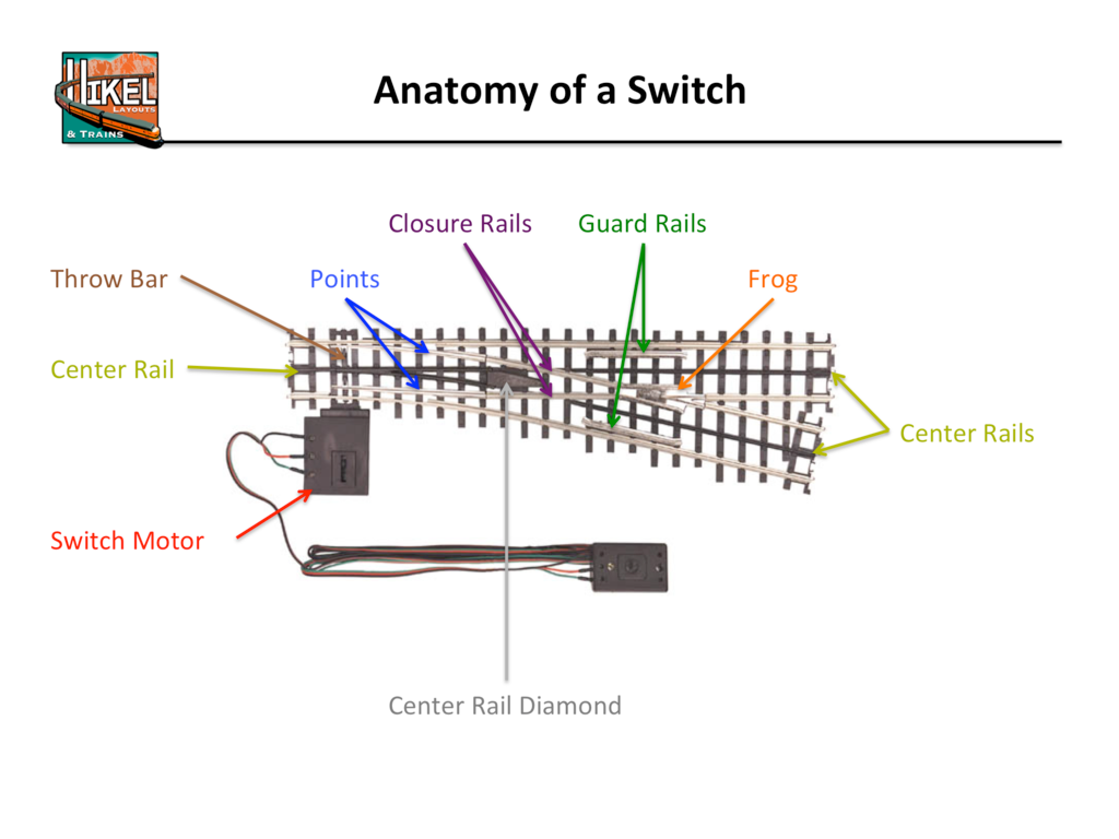
This discussion will use several terms to describe particular switch components that may be unfamiliar to some. Here’s a little switch anatomy diagram I made a few years back…
The most common problem with first generation ScaleTrax switches was a loss of insulation between the metal frog and the adjacent rails; potentially leading to short circuits when a train traversed the switch. The quality control on the first generation ScaleTrax switches left a lot to be desired. Often one or both of the closure rails made contact with the frog. Additionally, the stock rails leading out of the frog were never designed to be insulated. Insulating the stock rails from the frog is not necessary for safe operation through the switch, but it is a convenience for adding electric non-derailing or signaling. On original switches we added thin styrene shims between the frog and the four adjacent rails, and recommended MTH alter the mold to inject plastic to hold the gap. The new batch of switches does not have plastic in the gaps, but the quality control has been greatly improved. I inspected a dozen of the new switches and did not find a single offending gap.
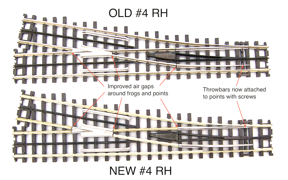
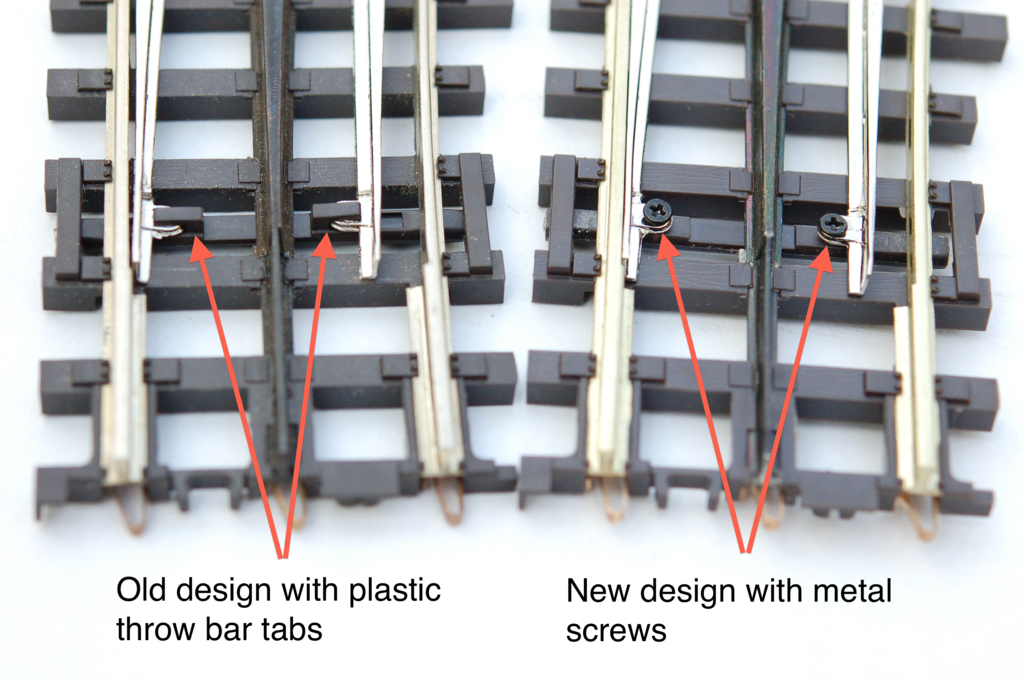
A literal weak point of all original ScaleTrax switches was the throw bar. The bar design included two plastic tabs that clipped on to the points. It was not uncommon to damage one or more of these tabs if you tried to drill the throw bars for Tortoise switch machines or handled a switch without care. As we recommended, MTH has redesigned the throw bar, replacing the plastic tabs with metal machine screws.
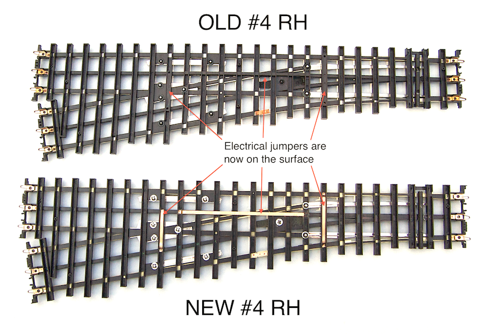
The process of applying electrical jumpers has also been changed. Some, though not all, electrical jumpers on first generation switches were applied to the rails before the plastic was injected into the mold for the ties. The idea was that the bare jumper wires would become encapsulated in plastic and would therefore be insulated from other switch components. Atlas attempted a similar design when they first introduced their 3-Rail O “21st Century” track in 1997. Both manufacturers encountered shorting problems when the bare wires would “float” to the surface. Approximately 2% of original #4 ScaleTrax switches had a jumper failure that connected center rail power to the frog, and 1% of original #6 switches failed when the center rail jumper contacted the diverging route closure rail.
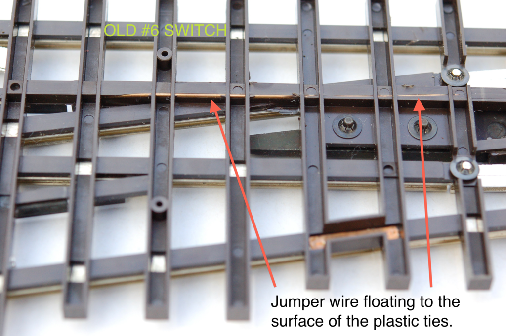
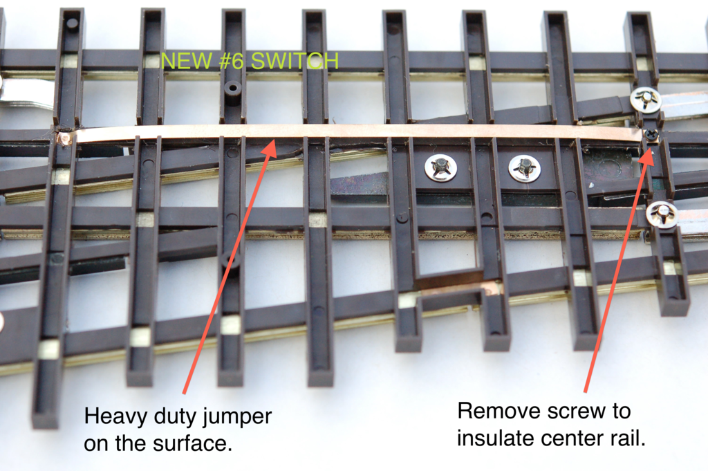
The new design installs all the jumpers after the plastic is in place. This ensures proper insulation in every switch and makes it easier to remove a jumper when you want to isolate track power. The long center rail jumper on the through route even has a small screw so you can easily break the center rail connection. Most importantly, the jumpers are a nice heavy gauge strip that can safely carry a LOT of current.
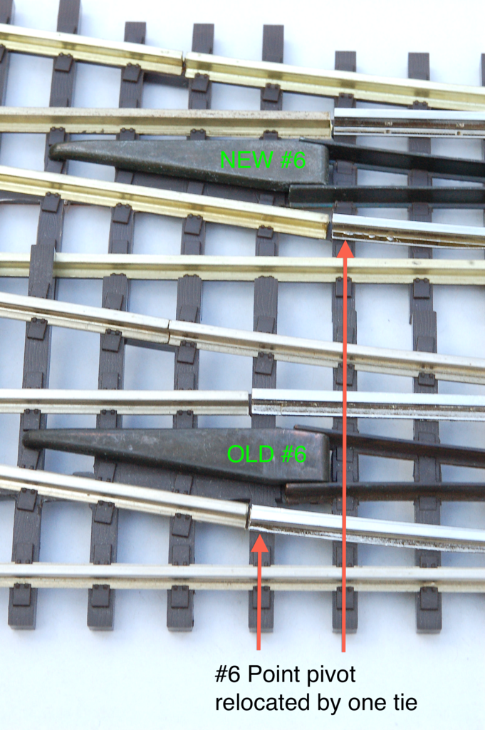
The most radical change of the new production run applies only to the #6 switches. The original switches had a design error that was only noticeable when running a few select locomotives. The pivot of the switch points on original #6’s was very close to the pickup roller path. Locomotives or cars with extra-wide rollers could contact the point and momentarily energize the point with center rail power. A direct short resulted if that moment of contact coincided with the back of a wheel rubbing against the point. The only locomotives I have found to date with exactly the wrong geometry to induce this problem are Atlas FM Erie Builts and Atlas C-628/630’s.
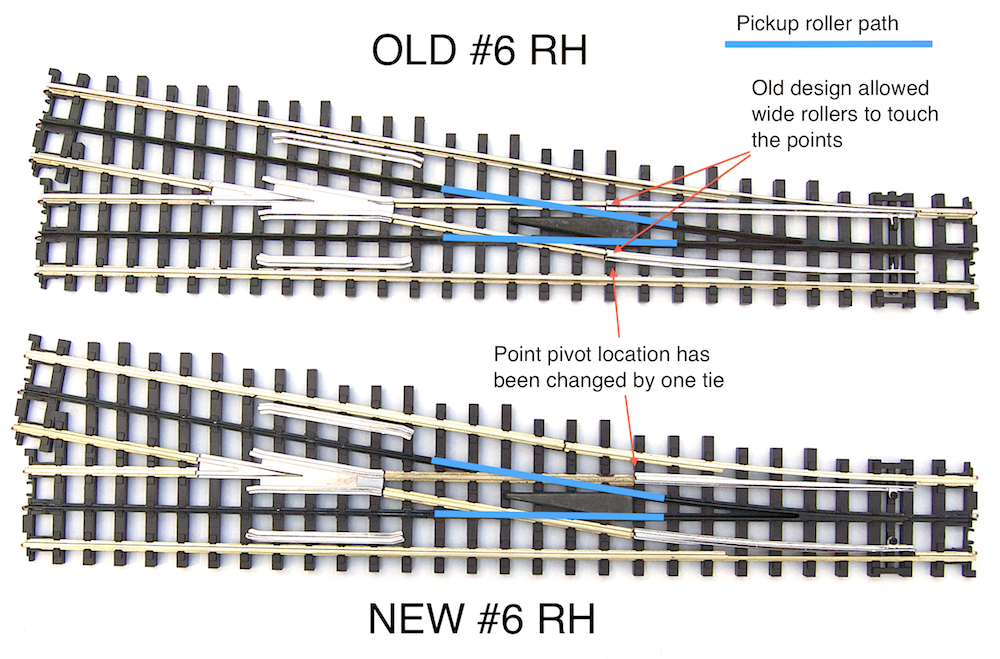
MTH has corrected this rare problem by shortening the points on the #6 switches and re-locating the pivot point away from the pickup roller path by one tie.
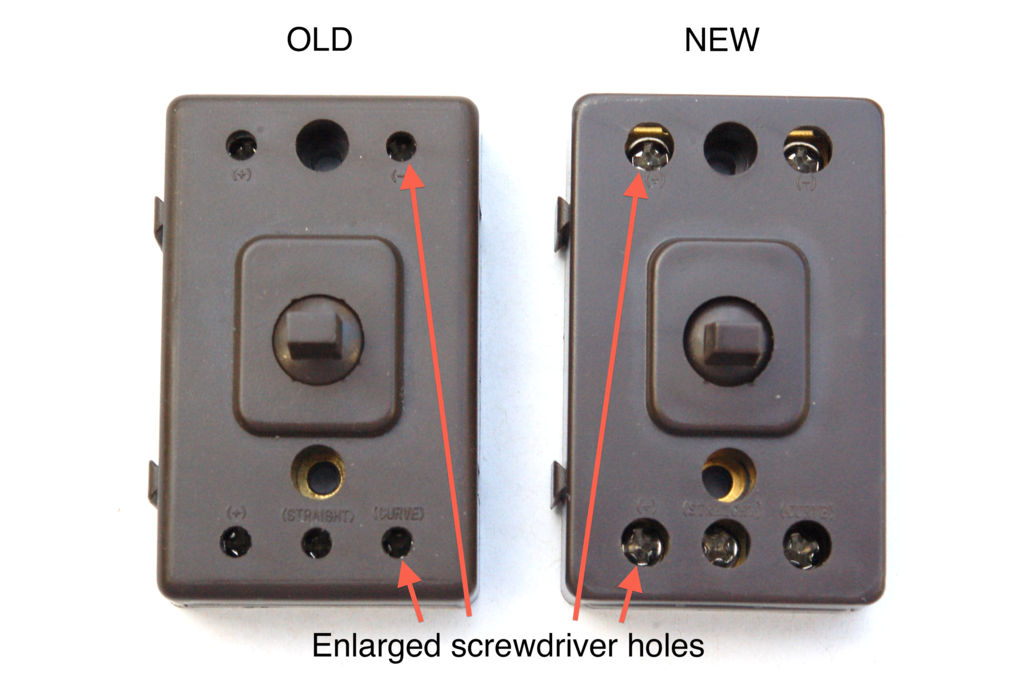
Improvements have also been made to the activation buttons and switch motors. ScaleTrax switches come with an excellent set of wires for hooking up to accessory power. The wire sets are pre-terminated with spade connectors that fit nicely under the mounting screws on both the switch motor and activation button. Each contact is held by a #2 phillips head screw inside the plastic case of the button or motor. However, the holes in the original case designs were only large enough for #1 or #0 screwdrivers. The holes have now been enlarged to accommodate #2 phillips screw drivers. Not all of the buttons and switch motors in my new shipment have the enlarged holes, so it appears that MTH is working through old stock of button and motor cases.
Probably the single most important improvement MTH has made is something you’ll never see. Inside each switch motor is a tiny little device that adds a LOT of safety. Each motor now has an automatic re-settable circuit breaker attached to the (+) terminal.
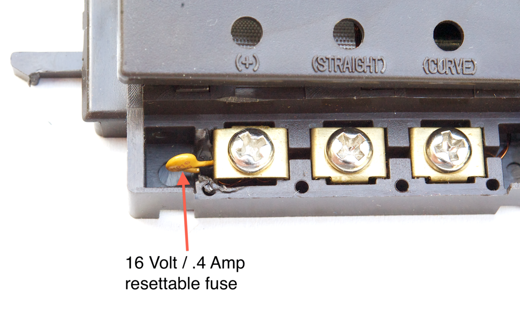
With original ScaleTrax switch motors it was important add electrical protection against a stuck activation button or inattentively leaning against your control panel. If power was applied to an original ScaleTrax switch motor continuously it generally didn’t draw enough current to trip the circuit breaker on a typical accessory power supply, but it did generate enough heat to melt the plastic case and/or burn surrounding scenery. With the addition of the resettable breaker, the motors are now protected from activation failures. It also allows you to safely add electric non-derailing without additional control hardware. One point of caution is still in order. The breaker is only rated for 16 volts. Higher voltage could cause the breaker to fail with repeated tripping. If you run your switches off of track power and you run command control with 18 to 20 volts constantly on the track, you could wear out the breakers. Use an accessory power supply, such as the 14 volt accessory output on a Z-4000 or Z-1000, and you’ll be fine. The breaker will trip after roughly 5 seconds of continuous draw at 14 volts. The breaker will remain tripped until the short circuit is removed. After the short is removed, the breaker will reset in 3 seconds.
Hope some of you will find this information useful.