Good news -


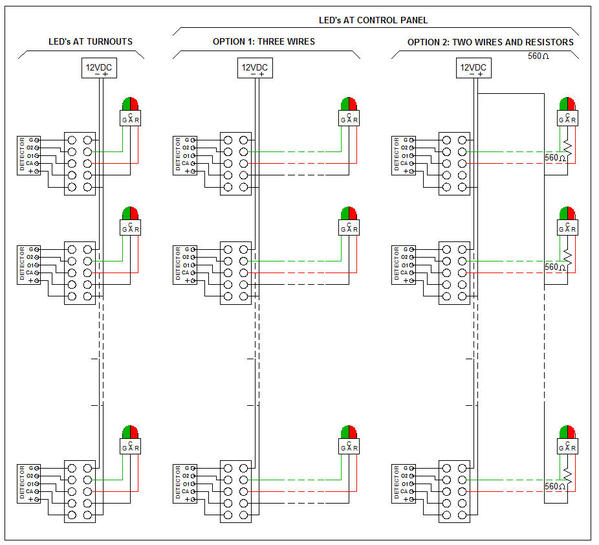
I found a way to incorporate the resistor I mentioned (R1, above) within the detector PCB, so the end-user will not have to mess with it.


Now all the connections for the LED's will be available at the detector PCB or at terminal strip connected to the detector PCB.


I'll keep you posted regarding timing.


Alex


PS. Terry, I too am rather excited now as I can see the light a the end of the tunnel, and it is not an oncoming train, but an LED!

Last edited by Ingeniero No1

I am ready to place an order for the Points Position Non-Contact Detectors, and would like to know in what type of sensor(s) and how many you would like to try this first go around.


In trying to keep within the forum rules and guidelines, I am not posting any specific descriptions or prices here, but have instead started a thread in the For Sale or Trade forum with all the details.


Please visit that thread here Detector Details


Thank you for your time and help.


Alex

Originally Posted by EastonO:

Thanks for the update. Regardless of timing, I'm excited about this product! It's moving forward!  Terry

Terry,

I tried to email you twice earlier this evening, but both emails bounced even though the address was the same as I successfully used a couple of weeks ago. Please, email me again and maybe I can connect.


Thx!


Alex

LED's IN PARALLEL


Another unexpected benefit from the new detector design is that it does allow some LED combinations to be used in parallel, as brought up by RTR12 on August 2.


While with the previous design I couldn’t get any combination of LED’s to light up properly when connected in parallel, I have tried several combinations with the new design, and some combinations work just fine. Do keep in mind that the total current is limited, which means that the current for each of the LED’s connected in parallel is less than if the LED’s were alone without a ‘sibling’, so they will light up, but not quite as brightly.


Some examples:

(1) A bi-color (green & red) LED close to the detector (at the turnout) and another bi-color LED at the end of a 20-foot. 26AWG wire (such as at the control panel) = OK, they light up just fine.


(2) Individual green and red LED’s close to the detector and a similar pair of individual LED’s at the end of the long wires = OK, they light up just fine.


(3) A bi-color LED close to the detector and individual green and red LED’s at the end the long wires = OK, they light up just fine.


(4) Individual green and red LED’s close to the detector and a bi-color LED at the end of the long wires = NOT OK, the bi-color LED barely lights up.


Bottom line: The type of LED’s used will determine how well they can be used in parallel, such as one (or a pair) close to the detector on the turnout, and the other LED or LED’s at the control panel.


Just thought you may like to know.


Alex


PS. Terry, I emailed you a while ago and so far it has not bounced.

Last edited by Ingeniero No1
Originally Posted by gunrunnerjohn:

I would point out that when paralleling LED's, you shoulduse the identical makes and types for best results.  Different LED brands have subtly different operating voltages, and in some cases only one of them will work, or they'll have vastly different intensities.


No question about it, John. Even though I was able to get some dissimilar types to work together, the light output of one of the LED's usually was barely acceptable. Only the same types lit up equally.


I recommend that anyone who wants to use the LED's at the turnout in parallel with LED's at the control panel, should test several combinations with the actual wiring to see what LED's work best. 


Thanks!


Alex

Several of you guys have expressed an interest in a yellow light to indicate the points out of position, so I gave it more thought and more testing (see below for work leading to this). With the present detector design, all it takes is a common-cathode, bicolor (red-green) LED, and one more resistor to make the points out-of-position signal appear yellow.


But how good is it? I personally prefer the no-color or white option to indicate the out-of-position points, but this undoubtedly is a question of taste and preference. Here is the present design detector PCB, with a common cathode bicolor LED using a 560Ω resistor (as will be built in the next batch of detectors) and a 1.5KΩ resistor. This combination of resistors gave the best yellow color. Ambient lighting will affect how the colors look.


Signal GrnYelRed


Here is the common-anode bicolor LED I am using, which is off and appears white when the points are out-of-position. The required resistor for this approach will be included in the detector PCB. (Please refer to my post yesterday for wiring diagrams.)


Signal GrnWhtRed


Previous work:


When I started this project a couple of years ago and after deciding to pursue the approach that eventually became the simplest and least expensive, the points indicator signal was indeed Red-Yellow-Green. I used the more readily available common-cathode bicolor LED, and it required a bit more circuitry than the current design, but it was not too bad.


By the way, although it is possible to have three individual LED’s; namely a red, a yellow, and a green, the circuitry involved would make the cost too high, in my opinion.


The biggest problem was to make the bicolor Red-Green LED appear orange or yellow when both segments were on – it just did not look right at all. It did not look right when placed by the turnout, so I decided that at least for signals that would be near the turnout, the yellow-orange option was out. However, maybe it would be OK at the control panel.


After a number of trials, I still could not easily discern whether the lit LED was yellow/orange, or pale green or pale red. The actual color, when both segments were on, depended a lot on the LED itself, on the ambient light, and on the current flowing through each color segment. I played with this for a while but never reached an acceptable (to me) solution, so I pursued the next option; i.e., the Green-White(off)-Red approach.


Alex

Attachments

Images (2)
  • Signal GrnYelRed
  • Signal GrnWhtRed
Last edited by Ingeniero No1

Alex, I agree that having the yellow/orange is probably not the ideal situation, it could easily be overlooked.  However, as I said before, if you have a lot of switches, the absence of a single LED indicator is also easily overlooked.


I'd like to see a flashing LED that monitors all the points sensors and let's you know that one has taken too long to transition and is probably stuck.  This could be an add-on module that just senses whether either of the LED's are lit for the two positions.  Also, one LED (or even a beeper) would be far more recognizable as an error annunciation.


I know this doesn't fit into the existing circuit, and I'm not suggesting you add it.   I'm just suggesting as a future add-on, it might be popular.  If all the LED's were paralleled on a panel, you'd have a common connection point to add the monitoring without a lot of long wire runs.


Here is a very short video of the Non-Contact Point True Position Detector on an RCS Turnout. Note that the RCS/DZ signal does not always indicate correctly the position of the points.


The Detector Evaluation Kits I made up with existing parts appear to be working well for the guys who have had the chance to install them already. The kits are a great way to become familiar with the detectors. Production detectors should be available in about three weeks, but I have a few parts left to make evaluation kits. I have listed these in the FOR SALE forum.


Alex

Last edited by Ingeniero No1

A few days ago I received the first batch of production units, have been testing them, and they work great!


The new detectors allow the LED's to be connected directly to them, if you want. This is best when the signal (LED's) will be mounted close to the turnout.


The LED's can also be mounted at the control panel. I just tested several at the end of an 80-ft long, three wire cable (24AWG), and it worked fine. However, if you have many (what is many?) turnouts, you may elect to run only two wires from the detectors to the LES's at the control panel as long as you add a 560Ω resistor in series with each LED common anode. The resistor will then be connected to the (+) of the 12VDC supply.


ALSO, as many of you had desired, you can have an LED at the turnout and another at the control panel for the same turnout! This can be done by adding a 430Ω resistor in series with the common anode of the LED at the turnout, and 1KΩ to the LED at the control panel. The 430Ω resistor will be in series with the detector 560Ω resistor, for a total of 990Ω, which is pretty close to the 1K (1000)Ω resistor at the control panel. These will limit the total current of both LED's so the detectors can light them both.


Some configurations:

 For Single LED's

Detector LED connections - single LEDs


For Dual LED's


Detector LED connections - dual LEDs


I just posted a thread at the For Sale section of the forum with pricing for the components.


Please, bear with me while I get all this listed properly. If you have any questions, I will be checking the forum regularly, so you can ask here, or email me.


Thank you for your patience!


Alex

Attachments

Images (2)
  • Detector LED connections - single LEDs
  • Detector LED connections - dual LEDs
Last edited by Ingeniero No1

Joe, Chad, Choo-Choo Kenny -


I now know that I did not order enough detectors to meet the demand, so I will be ordering again. Fortunately, it takes my supplier (in the USA!) only about three to four weeks to ship the detectors after I place the order.


I would really appreciate if you would be so kind to email me with the quantity you want, Atlas or Ross, and I will place another order in a couple of days. PLEASE, check the pricing in the For Sale forum.


Joe, no; unfortunately I will not be able to make it to York this year.


Thank!


Alex


Add Reply

Post

OGR Publishing, Inc., 1310 Eastside Centre Ct, Suite 6, Mountain Home, AR 72653
800-980-OGRR (6477)
www.ogaugerr.com

×
×
×
×
Link copied to your clipboard.
×
×