Hi:

I believe I have finally perfected my switch technique to produce a very acceptable switch and it only took till switch #5.  My first 4 were good, but finally I feel comfortable with the most difficult part, the frog.

The quality is determined by how quietly a metal wheel truck moves through the frog assembly.  The  key is to use an NMRA wheel and flange /track gauge.  Also, work from the straight stock rail and make all radius modifications from there.  Be sure the truck wheels are gauged as well.

Make your own simple frog alignment/soldering tool or jig.  This helps with belt sanding the angles.  Also, the rail can be pinned down to ensure flatness and stability by inserting pins thru short pieces of tie cut-off pieces while soldering.

The frog takes a lot of solder and after use a saber saw blade held by vice grips to obtain the correct flange depth.

Note that the Flange opening follows a straight line from the heel to the toe.

Note also a scrap piece of aluminum nailed where the frog is soldered to keep from burning up your jig.

Thanks for looking....


Attachments

Images (5)
  • P1070458: #5 Switch Frog
  • P1070459: #5 Switch Frog
  • P1070460: Alignment and soldering jig
  • P1070462: Completed #5 Switch
  • P1070463: Completed #5 Switch
Last edited by Tom Burke
Original Post

Replies sorted oldest to newest

IC EC:

I am using Alhpa Metals SN62 PB36 AG2 .020" Dia. Solder with P2 Tin Lead Silver Rosin.  But, I do a very light coating of plumbers flux on the parts to be soldered.  This is the flux sold for Lead-free solder.

Because I am using electronics solder that is only .020" in diameter I sometimes take about 6 strands and twist them together because of the huge amount of solder required on the frog.

After completion, but while the frog is still warm I scrub with a toothbrush, brass wire brush it and then scrub it in hot water with cleanser using a toothbrush.  Then clear water rinse.  This is mostly to rid it of excess rosin from the Alpha, which can be considerable.  

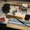
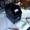
I  use a standard electronics adjustable soldering iron to flow the solder, but use a resistance soldering rig (home-made) to attach the 90 degree holding rails.  Using the relatively thin rails allows less cleanup after the rail is spiked down.  Having the aluminum plate under the frog allows plenty of heat to flow the solder and drive away the rosin during joining.

My home-made resistance soldering unit uses a huge 3V transformer controlled by a variac set at 90VAC.  

Tom


Attachments

Images (2)
  • X-M Tul Jel Sold 014: Bench Test Res. Soldering Unit
  • 20130213_193707: Encased Res. sold. Unit

IC EC:

Maybe this will help:

I was where you are about a few months ago.  I watched every u-tube I could on building switches and laying track.  I even watched an old how-to program on "tape" I taped off PBS years ago with Lorell Joiner doing track and switch work.

Next, I downloaded the Fastracks templates for my #5 switch and you now see the results.

ps - My motivation?   These things are selling on e-bay for $90 each and I needed 18.  And that's without ties and spikes...  Yikes

Best of luck with your switches and trackwork.

Tom

Add Reply

Post
The Track Planning and Layout Design Forum is sponsored by

AN OGR FORUM CHARTER SPONSOR

OGR Publishing, Inc., 1310 Eastside Centre Ct, Suite 6, Mountain Home, AR 72653
800-980-OGRR (6477)
www.ogaugerr.com

×
×
×
×
Link copied to your clipboard.
×
×