Hey everyone,

So I am currently in the process of producing modules that are powered by the electricity coming out of the transformer (Track power) and take three inputs: the two bulbs and one common ground.  5 wires total and will be perfect for insulated track sections.  This module will flash two bulbs accordingly, just like a real railroad crossing.  Lionel 154 styled configurations would be ideal, as shown in the demo video.  The box will be a literal "Plug N' Play" solution.  

https://www.youtube.com/watch?v=VMXOj8cgv98

I will be selling these sometime in the next year.  However, I will make a video on how to make it yourself if you'd like to spend some time debugging.  If anyone is interested in getting some, send me a message, and in the future, I will post the link on eBay.

As far as doing it yourself, I can answer any electronics questions, as I am an electrical engineer.  I would be more than happy to give advice on this matter, or any other electronics questions.


Last edited by Datdupa46_Novotronics
Original Post

Replies sorted oldest to newest

Presumably you'll be making a custom circuit board.  At the risk of feature-creep, how about adding a sound option.  For about $3 in modules (free shipping from Asia) you can get an MP3 player with built-in speaker.   A microSD memory card stores the sound which in this case could be a single MP3 file of crossing sound.  Turn it on (apply power) and the player starts the sound.  In this case the player has a built-in rechargeable battery but for your application you could supply DC voltage directly.

ebay parts

Attachments

Images (1)
  • ebay parts

John,

Sorry for the late reply.  Recently, I am trying to perfect the time delay.  It appears that this particular application for crossing lights would be about a 1 second period at 50% duty cycle.  Half of a second on and half of a second off.  The only thing I am worried about with a larger capacitance would be current gain specifications of the transistors.  A pair of resistors have to be less than the current gain of the transistors, due to a larger Early Voltage.  This can also cause a phenomenon where there is never saturation of the transistors and leaving the bulbs both on.  I am currently working on optimizing simulation as of now and found larger resistors and small capacitors will do the trick, almost .5 seconds on for each.  However, this may not be compliant with current (too low).  I will have to experiment with it and post back here with some waveforms and such.  This is what I have so far. 

Stan, 

This is something I have greatly considered.   This looks like a really interesting product and I will have to give it a go.  I wonder if half-wave rectified would have any adverse effects on the circuitry.  It could potentially cause non-linearity and start tampering with the sound frequencies, making the sound even worse.  I can easily correct this with a full wave bridge rectifier.  I will order it and see if I can get a working prototype.  The only thing I am worried about is longevity of the sound module.  I may have to reverse engineer that product.  If I am selling it, then that may become a problem.  Either way, it would still be fantastic to have for my own layout.


Best,


James 

Attachments

Images (1)
  • mceclip0
Last edited by Datdupa46_Novotronics

If you end up fooling with the $2 MP3 module, note that the MP3 player IC chip can decode stereo with 100% channel separation.  In other words you can put two arbitrary and independent sounds in your MP3 file.   What is not obvious is you can take advantage of this and store the crossing sound on the LEFT channel and the alternating flashing signal on the RIGHT channel.  The key point is the waveform is DC-coupled which is also not obvious.  And you can go down to DC - not just the 20 Hz to 20 kHz you think of for hi-fi audio.  Thus you can literally "paste" your simulation square-waveform you posted above into the RIGHT channel and when the MP3 file plays, the right output signal will replicate that waveform going hi and low every 0.5 seconds or whatever.  High means going to full-scale DC, low means going to 0V DC, and mid-scale goes to half the DC supply voltage.

This makes for interesting possibilities.  So you don't need to construct a timing circuit with transistors, 555 timer IC, or whatever.  You simply "draw" the timing signal you want and insert it into one audio channel.  You can set the waveform flashing timing to whatever you want ... no need to adjust capacitor values, no need to adjust a trimpot variable resistor.  If you want to change the timing, you just edit the audio file.  If a customer wants different timing you send them a new MP3 file by email rather than new hardware. 

Note that while using a PIC microcontroller also "eliminates" capacitor/potentiometer adjustments to set the timing, if you want to change the timing you are modifying a program.  Very few customers would have the programming tools to modify the program much less re-program the microcontroller chip itself.  On the other hand, "free" audio editing programs are readily available and re-programming a microSD memory card is as easy as drag-and-drop on a PC or laptop.  In fact, some of the low-cost MP3 player modules even have a mini-USB connector that support file-transfer so you can just connect the MP3 player to your PC/laptop via USB cable (which typically comes with the MP3 player) and you can drag-and-drop an MP3 file right into the player.


Last edited by stan2004

Stan,

This is really fascinating!  I will have to try this out.  Unfortunately, in order to make this a plug and play AC solution there needs to be a bridge rectifier and MOSFET switching controlled power supply, due to different power requirements for the two channels. The second channel would need more current to supply the bulbs.  This is absent from the MP3 module.

Another potential issue I see with this is simply the minimum current of most incandescent bulbs for illumination, vs the MP3 player's maximum current draw on each channel before it breaks down.  I have a feeling it will be in the 30 mA to 100 mA range.  Most Lionel bulbs need much more than that.  However, it would be interesting to add that in the mix for LEDs.  This way, there could be a switch that the user flips on the outside of the box to send the fully programmable time delay, or switch to the AC mode with the other circuit I have.  I also would have no issue with writing software for driver interface with the guy, so the user could just enter the time in an interface and download the code to the board.

Thanks, everyone!  I really like the functionality ideas  Stan you have really knocked it out of the park with this one.  I will keep you all updated on the design.


James

We're doing this stuff for enjoyment and personal gratification, sometimes you hit on something that strikes a cord with enough people that it becomes a salable product.  Other times you end up with something handy for your own use.  And, occasionally you end up with something that just didn't work out like you expected and it is in your scrap pile.

FWIW, all of my little products originally came out of a need for such functionality for my use.  In discussions in various venues, it was apparent that others wanted/needed similar functionality, so a product was born.  I have lots of other little projects that I still use personally, but I didn't see the volume necessary to commit to a build run, here's a few that didn't make the production cut.  FWIW, I can make the PCB design available for any of these on request, you can get boards produced on the OSH Park PC Fab Website quite reasonably.

A couple of track powered DC supplies, first one based on a variable voltage eBay switching module and is good for around 300-400ma. 

The second uses a TO92 regulator or a CL2 constant current regulator to provide either a constant voltage or constant current. 

I've used these in a number of my projects, and occasionally people have bought a couple from me, but I haven't done a production run as I don't see the volume demand that would justify it.  For stuff like this, I also include a 22uh choke for DCS compatiblity.


The DCS continuous barking watchdog generator.  This was an idea that Stan dreamed up to stick onto the MTH DCS remote Commander to create a continuous watchdog signal generator for using in places like yard tracks.  I had a run of boards made and a number of people used these.

Track powered LED Flickering Firebox module.  Stick this behind the firebox opening in a steamer and you get a neat flickering firebox effect.  I use these on upgrades that I do.

Locomotive motion sensor.  This is a simple module that just monitors the motor and anytime the locomotive is moving, it closes the relay to allow various events to take place when you're moving or stopped.  You can do stuff like Rule-17 lighting, automatic cab light control, or smoke intensity control.  I've used these in a number of upgrades, some of mine, some for other people.

Here's another Stan inspired design, I don't know who actually built this one, but I believe Stan did.  This is a single resistor adjustable power module that does constant voltage, constant current, or you can also tap off the raw DC voltage if you have a special need. 


Attachments

Images (7)
  • mceclip0
  • mceclip1
  • mceclip2
  • mceclip3
  • mceclip4
  • mceclip5
  • mceclip6

James, I'll be most interested in following along what you come up with.

When it comes to assembling a sale-able product you run across the curious situation where the eBay assembled modules cost less (often MUCH less) than the individual components.  As you've pointed out, this can be an issue as these modules come and go.  But I think in most cases, with some thought about what your true value-added is, you can design your product that adapt to changes in underlying components.  If you're not familiar with the OSH Park circuit board process that GRJ mentions above, take a look at how you can get attractively priced prototype quantity boards...and make those boards available for others to purchase directly. 

However, I think you will find that on OGR, most guys would just as soon buy completed, assembled-tested, widgets rather than the hassles of procuring small components, soldering, wiring, etc.  A big issue is aging eyesight which apparently is not a factor for you!

Anyway, to your previous comments, if you put the alternating lamp control signal on one channel of the stereo MP3 file you must buffer that signal.  Whether this means just using a $1 relay to allow toggling between arbitrary DC/AC loads...or using transistors to toggle between DC loads is a design decision.  I found this previous thread with more info on the concept of using the "unused" stereo audio channel in an MP3 file to encode something other than audio itself.

https://ogrforum.ogaugerr.com/...83#43383976950158183

The concept is based on what Disneyland and others refined in the last century with so-called animatronics (animation electronics) using multi-track tape (audio) recorders.  I initially thought to put touch-tone audio signals since I assumed you could only store "audio" in MP3 files.  I was quite excited to discover I could encode DC-coupled signals.  As shown in subsequent posts I demonstrate how this could be a serial-digital signal with sufficient baud rate for controlling digital devices with a serial control port.  Not shown is the idea of storing a digital PWM servo control signal so that the spare channel directly controls a servo's angle synchronized to the audio on the other MP3 channel.  In each case you need to at buffer the low-current, low-voltage analog MP3 output to create a suitable voltage swing (e.g., 5V) and drive capability.

In re creating a UI.  If this is to allow the user to alter the flash timing, I don't think you'll find many takers.  If you simply provide something within FRS spec that ought to satisfy 99% of the guys.


Design Update:

I have added a full wave rectifier stage along with a buck converter for the MP3 module to go with it.  I am just awaiting the MP3 player to give this a go!

Stan,

Thank you for all the advice!  I will post all my experiments up here so you all can see.  Fascinating history, by the way.  I will also try and look into just using the MP3 device to try and control the flashing as well.


James

Datdupa46_Novotronics posted:

I am currently in the process of adding the MP3 sound module in.  Great idea!  It is really easy to modify that PCBA inside of the MP3 speaker.

To be clear, by MP3 sound module you mean from this?

mp3 player

which dis-assembled looks like

IMG_2255

Are the markings on the two IC chips exactly as shown below?

IMG_2694


Attachments

Images (3)
  • mp3 player
  • IMG_2694
  • IMG_2255
stan2004 posted:
Datdupa46_Novotronics posted:

I am currently in the process of adding the MP3 sound module in.  Great idea!  It is really easy to modify that PCBA inside of the MP3 speaker.

To be clear, by MP3 sound module you mean from this?

mp3 player

which dis-assembled looks like

IMG_2255

Are the markings on the two IC chips exactly as shown below?

IMG_2694


Stan,

Yes, that would be the one.


James

Datdupa46_Novotronics posted:
 
... So I think it is competitively priced, plus you can put whatever crossing sound you want on there.

Not just a crossing sound but any layout accessory sound!  As GRJ (rightfully) accuses me of, I am the master of feature creep.  LOL.

I believe there is a need for a simple, plug-and-play, accessory AC powered sound module. 

I don't know which direction you're going with the flashing light portion of the circuit but, for example, if you stored the sparking sounds of a welder and have the "other" MP3 track drive a flickering LED, you could use the identical module for an animated welder's station.  Just change the MP3 file!  So this would be a case where you store a "random noise" waveform in the 2nd audio channel to make an LED flicker...rather than a square-wave to blink a pair of lamps like clock-work.  I can think of several other accessories that could benefit from this capability. 

Ironically, as I understand it, crossing gates do NOT have synchronized sound and light.  That is, the dinging is not synchronized to the flashing other than they both come on at the same time.

I believe it's worth your time to pursue this and if it comes to fruition I'm convinced it will be a welcome addition to O-gauge.

stan2004 posted:
Datdupa46_Novotronics posted:
 
... So I think it is competitively priced, plus you can put whatever crossing sound you want on there.

Not just a crossing sound but any layout accessory sound!  As GRJ (rightfully) accuses me of, I am the master of feature creep.  LOL.

I believe there is a need for a simple, plug-and-play, accessory AC powered sound module. 

I don't know which direction you're going with the flashing light portion of the circuit but, for example, if you stored the sparking sounds of a welder and have the "other" MP3 track drive a flickering LED, you could use the identical module for an animated welder's station.  Just change the MP3 file!  So this would be a case where you store a "random noise" waveform in the 2nd audio channel to make an LED flicker...rather than a square-wave to blink a pair of lamps like clock-work.  I can think of several other accessories that could benefit from this capability. 

Ironically, as I understand it, crossing gates do NOT have synchronized sound and light.  That is, the dinging is not synchronized to the flashing other than they both come on at the same time.

I believe it's worth your time to pursue this and if it comes to fruition I'm convinced it will be a welcome addition to O-gauge.

Stan,

You really are the guru of feature creep!  Thanks for all the advice.  I will definitely try that stuff out.  I definitely want to experiment with that 2nd audio channel.

James, are you still working on this?  Here are a few more ideas (feature creep).

1. Volume control.  In looking at various sound accessory modules for train layouts, some provide a volume control knob.  The cheap MP3 players use pushbutton up-down volume control but the buttons can be really tiny and clumsy to operate.  Additionally, I notice that some MP3 players revert to a default volume level when you turn off power...no matter what you had previously set it to.  What a nuisance to have to adjust the volume every time the accessory turns on!  So I found a $1 volume control module that gives a size-able control knob.  Obviously the volume setting remains between operating cycles.

audio amp with volume control for a buck

Only one channel of the amplifier is used in the video example above.  The stereo earbud plug is used to access the Left and Right tracks of the MP3 player.  The Left track with the audio goes to the audio amp.  The Right track with the lamp control signal goes to the lamp decoder circuit described below.

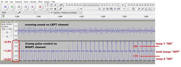
2. Dual lamp control.  Obviously for a crossing gate you have to control 2 lamps.  Initially I had thought of just a binary on-off control track that toggled a relay with NO and NC contacts to steer power to one or the other lamp/LED.  That can certainly be done and is simple.  But with less than $1 in parts, here's one way to control 2 lamps using one audio track with what amounts to a 3-level signal.

crossing sound and 2 channel lamp control audacity

Not all MP3 players "render" the waveform in this way, but for the $1 player shown in the video, a full-scale positive (value of 1 in Audacity) generates a voltage of about 2.5V.  A full-scale negative (value of -1) generates about 0.5V.  And a 0 or the mid-point generates about 1.5V.  By pulse modulating the two lamps at hundreds of Hz, the eye cannot see what's going on and it appears like true independent control over the 2 lamps/LEDs.  Many ways to do the circuit but here's one with a 10 cent dual comparator IC chip; one comparator trips when the incoming voltage is above 2V, the other trips when the incoming voltage is below 1V.  If the incoming voltage is between 1V and 2V, neither comparator trips and both lamps are OFF. 

mp3 spare channel 2 lamp buffer

lm393 and pfet for mp3 buffer

You mentioned fabricating a circuit board in which case using surface-mount components is practical - and of course if using a board service like OSH Park saves on square inches which directly drives board cost.  I see on eBay that a P-channel FET surface-mount that drives several Amps is only 5 cents.  That's quite reasonable if you need to drive current-hungry incandescent bulbs and can rectify AC accessory voltage since FET switch DC.  Otherwise for driving low-current red LEDs, a 2 cent PNP transistor with a few hundred mA of drive is suitable.

3. Brightness control.  A bonus of the above method is by pulse-width-modulating the lamps you can control brightness.  This means fading the brightness of each LED to simulate the filament decay in the incandescent bulb prototypes.  I notice many of the off-the-shelf crossing modules simply turn the red LEDs ON and OFF.  To each his own, but I find that the digital on-off effect to be somewhat sterile and like to see the lamp slowly extinguish.  Note that this comes for "free" in the circuit; the cost is generating a more complex waveform in Audacity which of course you only have to do one time.

4. Not just lamps for crossing flashers.  Nothing stops you from hooking up, say, a small DC gearmotor or whatever instead of a lamp or LED.  For example the dual-output capability could drive one LED and one gearmotor with light and motion sync'd to the sound on the main MP3 track.

Attachments

Images (4)
  • crossing sound and 2 channel lamp control audacity
  • mp3 spare channel 2 lamp buffer
  • lm393 and pfet for mp3 buffer
  • audio amp with volume control for a buck
Last edited by stan2004

James

Are you still working on the simplified version of providing crossing bell signs as described in your original thread? If you are please refer to my comments there and those from Stand and GRJ and respond in that thread. I don't want to inject non related questions into this thread. The above discussion by you, Stan and GRJ although very interesting they are way above my pay grade.

Thanks Gerry

Add Reply

Post

OGR Publishing, Inc., 1310 Eastside Centre Ct, Suite 6, Mountain Home, AR 72653
800-980-OGRR (6477)
www.ogaugerr.com

×
×
×
×
Link copied to your clipboard.
×
×