
The wife has given permission for me to put an around the room ceiling/shelf loop in our bedroom.  I have come up with a simple plan that'll allow for 2 trains to be up there, and we just pick which one to run.  Problem is our AC vent would be blocked by the platform.  The vent is near the corner, so if I make the turn into a bridge, then the flow of the cold air required for survival in the AZ desert will not be blocked.  Does anyone know where I could get a bridge, or have info on building my own (Which I would love to do.) that will support the weight of and have clearance for a scale Big Boy while only being anchored at the two ends?  Below is a SCARM plan of the room with the track.  The black box in the lower right is the AC.


Mbed v3


I'm thinking something like this, only curved.


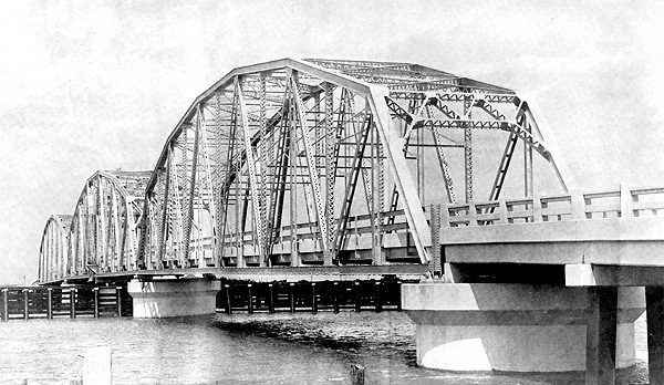
But a segmented bridge like this would be okay too if need be.

Attachments

Images (1)
  • Mbed v3
Original Post

Replies sorted oldest to newest

Fairly easy to make 072 [@ center rail] curved plate truss type bridge. As shown is unfinished. Steamed and bent poplar used but Masonite is far easier to curve. 

Last photo is a straight version used as a drop entry section carrying 072/084 dual mainline on another layout. Made with Masonite sides.

100_1080

100_1196

IMG_1636

Attachments

Images (3)
  • 100_1080
  • 100_1196
  • IMG_1636
Last edited by Dewey Trogdon

Well, with outside temps going 110+, it's AC > trains because the trains would cook otherwise.  It's bad enough I have to keep the house 80 inside or else the AC runs all day long  It hasn't dipped below 100 until 9-10 pm every night this week.


It would be a single track bridge of 4 pieces of Atlas 3 rail O72 track, as seen in the screenshot at top, in the lower right corner where it isn't green.  The main thing is I don't have the scale Big Boy yet to know the clearance needed on the outside.  And if I buy aluminum to make the bridge, I don't know how I'd "weld" it all together.  Maybe I can do a metal plate for the base and build the sides with wood and paint it silver.

Below is a video of the "around the room" shelf I built for my daughter's room, out in Colorado.  It incorporates a 90 degree O-72 bridge, as you are describing, that we needed in order to clear the alcove for the door.  Since a die cast locomotve represents a lot of cantilevered mass, we added the center support (consisting of threaded rod and wooden plates) that connects to the ceiling joist for extra support.  Bridge we used was from Bridgeboss Jim (and it was perfect for our needs)... though the exact one we used won't meet your requirements given the swing clearance required for a scale articulated (semi-scale articulateds wouldn't clear our O-72 single track bridge).


-Dustin


Last edited by frizzinbee

Sinclair

Bridgeboss Jim as noted above, is the guy who can fabricate what you need or at least advise you if you have the skills to to handle it.

I did measurements on an 072 curve to determine clearance for my Challenger. The pilot overhang was not the furtherest extension--it was the corner at the running board's front edge and, on the rear, the rear corner of the cab roof. The pilot is "tracking" the curve while the boiler is still going straight for a moment. [my 072 curves are 36" radi to center rail formed from Gargraves flextrack.]


The very minimum clearance at either point, front or rear, was 2-1/8" measured from center rail. With the engine in the curve I placed a miniature framing square against the extended overhang points for an accurate mark on the layout surface and measured back to the center rail.

I used a clearance to plain wall/tunnel walls in a curve and to bridges of 3" from center rail. This also clears 80'[20"] passenger cars with room to spare. Keep in mind that along side your siding[your drawing] that spans two curves that there is also inner overhang at the center point of both the engine and long cars-as I recall about 1-5/8" but it depends on what is hanging on a particular engine's sides--feedwater pumps, tanks,etc.


On my ceiling shelves[old 1992 photos below]I had eventually placed some building fronts/flats,half trees,etc, along the walls. I was careful to not place anything along the wall where the engine exited the curve--going either direction because that is where the overhang "reached out".

Someone who has a Big Boy can tell you whether the overhang is greater than the Challenger at any point including the pilot.

IMG_0002


IMG_0003

IMG_0004


Attachments

Images (3)
  • IMG_0002
  • IMG_0003
  • IMG_0004
Last edited by Dewey Trogdon

Dustin, I found your video via Jim's site after I posted my last reply.  That is very much like I want to do in my room.  And if I get hung up on trying to build my own, I'll be sure to talk to him about building one.


But Jim, I hope you're willing to advise me on trying to build my own until I throw in the towel.


Dewey, as for skills, I am comfortable working with my hands, I just don't have any experience, nor know the details for the Big Boy clearances.  I know Lee Willis posted that it was 3-1/8 on his, so I may go with 3.5 to be safe, but I don't know the in-hang.  As for that upper right corner, I know it's going to be tight, and the Big Boy will only be on the outside.  Otherwise all my other locomotives should miss my passenger cars.  The one that'll be really close will be my RailKing Cab Forward.  Everything else I have is O27/31.  I'll set it up on the floor and do some run arounds to make sure I don't need to tweak anything before I put the track up there.


I plan on putting some building faces and such on the walls, and have my brother in law paint a city skyline on a wall or two and some forest and countryside on the others.  My wife thinks it'll be nice to have it up there so we can lay in the bed and watch it go around, so I want to make it nice.

Originally Posted by sinclair:

 Guess I need to see if there is anything in the ceiling to bolt into at that location. 

For whatever it's worth: With our bridge, there wasn't a ceiling joist where we needed it to be (based on the bridge position).  I ended-up going up into the crawlspace and adding a (2x4) cross beam between two joists so there was a place to mount the bridge center support.


-Dustin

Last edited by frizzinbee

Add Reply

Post

OGR Publishing, Inc., 1310 Eastside Centre Ct, Suite 6, Mountain Home, AR 72653
800-980-OGRR (6477)
www.ogaugerr.com

×
×
×
×
Link copied to your clipboard.
×
×