
Running around the wall can have it's own problems.  One being running wires past doors.  This is just one method.  I used wire molding and just stacked them next to each other as needed.

Almost looks like garish door trim.

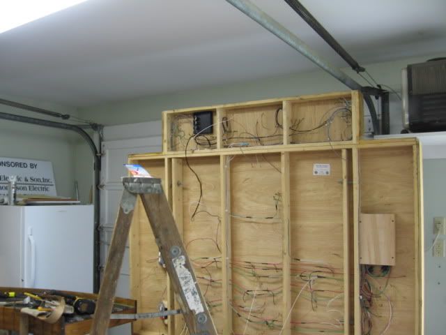
The 110 volt 20 amp is in it's own specially marked conduit through out the room with outlets every 8' +/-.  One switch off.  Shown is the  installation of the fourth run providing power for a yard area on the next module.

IMG_7357


All the other wire pairs are for different branch lines, town blocks, staging areas.

IMG_7360


Attachments

Images (2)
  • IMG_7357
  • IMG_7360
Last edited by Rich Melvin
Original Post

Replies sorted oldest to newest


Sorry, did not mean to confuse.

There are 4 wire moldings which hold a total of 19 wires.  Not 19 wires in one molding.

2 #10 & 2 # 12 in one long run,  4#@12 in  another fairly long run, 8 #14 in a third medium run  and 3 #12  110 volt  20 amp utility circuit in the fourth.  

200 linear feet of around the wall layout on  three levels and many different module units.  Five branch lines serving six towns inter connecting  two different mainlines.  

One main panel to run the whole layout with the option of six sub panels to run six local industrial towns/yards individually with either DC or DCS.

Not trying to impress, actually consider it a warning not to build too much. John Armstrong termed it "The monster in the basement".  Got it!  Too late!  I need to get someone in to shoot it.

My viewing will be track side, I'll be working on this till the end.

There is a total of five lift outs and three deep  valleys to conduit around.

I will not use floor moldings due to rolling equipment.  Plus, being a basement I do not want any accidental water exposure.


Standard wire mold comes in two sizes 500 and 700 (larger), 10 ft. lengths. At one time there were two colors, most seen today is an egg shell white.   There are flat "L's", as Tom has pictured, and attachment clips, (5703)'s,  that are designed to be used with the mold, to secure it to the wall.  Cut's easily with a hack saw.   You have to push, or fish, the wires through the mold, fittings are two piece, note the "L's" shown.  Top of the fitting, is installed/ clipped on, after the wires are installed.   Note that in most cases the metallic mold should be grounded.  There is plastic, non-metallic mold.  There is also an assortment of electrical boxes, ( example: 5747), designed to work with the mold.  Mold boxes will accept any standard electrical device or multiples. Also works with all standard electrical plates.      

Link to the on-line Catalog 

Last edited by Mike CT

Let me see if I still remember wiremold. Is it safe to assume that around the door you had to start closest to the door and pull the wire and snap the 90s on before moving to the next circuit? With all that so close together I would think it would be a nightmare to pull through the corners otherwise.


I do like the way it looks; It resembles brick mold trim. Is all the wiring in wiremold, or did you switch to a less expensive raceway where it wasn't so visible? Probably best not to talk about how much this stuff costs on this forum, as some members will gasp!


J White


I cheated.  I chose not to fish the wire.  What is not shown are all the tight turns and short runs.  Kind of a pain to fish tight multi angle pockets of turns.

I cut and fitted the empty  wire runs to dry mounted corners which had leads plugs drilled/mounted in the cinder block and cantilevered benchwork members.   Then I threaded the wire through the runs in mid air, pressed on the corners  then screwed them in the pre set holes.

Afterwards I caulked all the spaces and shaped a fillet between all housings from end to end.  "Custom Millwork".

There has just been added an unscheduled 3' X 19' peninsula  town and industrial site way down stream so another wire run is in order.  Next time battery, R/C.

Mike C.   If you happen to be in town I have a seat reserved for you.

IMG_7795


Attachments

Images (1)
  • IMG_7795
Last edited by Tom Tee

Why not make your own out of strip wood ans thin plywood.  Use the strip wood (1/2" square) and 1/4" plywood cut to the width needed for current and future wires.  Use two pieces: one to secure to the wall and to secure your wires to and the other to cover.  Attach the latter with screws so it can be removed.

Jan

I think it looks great.  You had a problem to solve and did a good job on it.  I don't think I would have noticed the "molding" around the door if you hadn't told me. 

I would define your solution as an example of preparation/ingenuity colliding with opportunity.

Darrel Royal always said that was the definition of Luck.

Our typical use of wiremold was to mount a wiremold box for whatever device, then run a piece up to and above a drop ceiling. At that point it went to an adapter and into a standard box, with thinwall conduit taking over. We rarely used the elbows (the inside corner ones were a real treat to get the wire through as I recall), but when we did, we typically fished to them and made a loop at each elbow. I don't imagine fishing directly through them would work at all.


Thanks for explaining how you did it. I studies your pictures and don't see any telltale blood stains of recent wiremold installation. That's something I never had much success with either. It seemed like even the softeners would find a way to cut me.


J White


Tom Tee posted:

................................................................................................................................

Mike C.   If you happen to be in town I have a seat reserved for you.

IMG_7795


Spent a good part of my life on my hands, knees, and backside.   This works well for me 

Even on the step ladder.


Mike, The 5000 system is slick!!, Really like it.  Thank you.  However, it seems as though the Access 5000 system only has   horizontal runs.  no vertical corners for running around a door frame???  Similar principal to GRJ's suggestion.

As far as routing out the baseboard, I did run into problems with a client who ran wires directly behind their baseboard.  While undercutting their baseboard for a floor installation, the saw suddenly stopped! 

Another non code method D.I.Y.ers  use is to leave or remove the bottom 1 1/2" of drywall to run 110 wires & 1/2" water pipes. 

I'll probably just use another run of wire molding,  it did not strike me as expensive and one would expect to know electricity was within it.

Plus, every now and then with a hurricane coming through there could be a dribble of water in the threshold area.

The wire on my layout runs in electrical ducting.

When I build the baseboard frame I use 6inch wide on the outside and 4inch wide cross members the 2inch difference on the outside allows the ducting to be attached then thread all the wires into the ducting everything is neat and out of the way.

Roo.

Attachments

Images (1)
  • DSC09517

Tom.

Yes the board is screwed and glued. Is there a reason for asking that? I know you build some very nice bench work I keep up with these things haven't stopped completely. I am not a woodworker in a true sense but I have all the woodwork tools and the space.

BTW forgot to mention.

I thought your way of putting the wires around the doorway was very neat I had to have a second look at the photos to pick up the wire molding couldn't work out what was so different in the photos. brain is getting slower in reaction time.

Roo

Roo, Sometimes I long for brain activity.

The beauty of a low end camera is that anything can look good, like beer eyes.

Instead of glue, on 3 rail layouts I use GE Silicone on top of frame members with #1 trim screws into 3/32" predrilled holes.  Then remove the screws the next day.  Not for structural integrity but to quiet the 3 rail noise.

Most two rail is open grid with flat plywood yards.

Mike, I had forgotten about another time earlier when I used your idea of a lift up  using "toy box lids". for ease of wiring and storage track access.  1 1/4% grade.

toy boxes 005

Shown are a series of linear lids on piano hinges for access to any area of any of the hidden tracks.

toy boxes 008toy boxes 012

The wire is inserted into routed out grooves to clear cross members

Attachments

Images (3)
  • toy boxes 005
  • toy boxes 008
  • toy boxes 012

Tom.

The project I am working on now is what I call "The Last Great Project" I have converted half my layout to a steel mill and all the operations associated with a Steel mill.

It is a real pity that this could be the last time that I might be building anymore baseboards I would have liked to have tried your technique using the silicone and removing the screws.

I think that is a good idea like the top sort of floats or is insulated very good mate.

It is not so critical with my layout as it is all slow running switching in a 27' X 27' room in the house, sorry to go off topic I don't post on forums very much anymore and when I do tend to ramble on I am 73 years old now.

Thanks. Roo AKA Neville.DSC00314

Attachments

Images (1)
  • DSC00314

ROO , if you invert the year we graduated from HS it reads  the same.  I too am on my last round up.

I sometimes did not use the silicone treatment on two rail pikes.  Two rail is somewhat quiet by design.  Three rail equipment can get a bit overbearing in the noise department.  Multiple 3 rail trains running at the same time can be annoying or deafening to some.

Your switching pike should be fine sound wise.

Add Reply

Post

OGR Publishing, Inc., 1310 Eastside Centre Ct, Suite 6, Mountain Home, AR 72653
800-980-OGRR (6477)
www.ogaugerr.com

×
×
×
×
Link copied to your clipboard.
×
×