Here I go chaps . . .


Port Elderley is a fictional waterfront area in the US - probably near the sea.    It's not too far from the village of Olpharts Crossing, so you can see that I don't take myself too seriously.  My journey from decades of HO to O scale came about when I acquired a kit for an ocean going tug boat.


Amster 06

This isn't my model, mine's not finished yet.  I decided to sell my two HO layouts, expecting that by the time the boat was done, the layouts would be close to being sold.


About halfway into building the boat, I thought it was time to advertise the layouts and they both sold; the day I advertised them!


So, here I am flush with money and a half finished boat.  The boat is 1 : 50 so a reasonable match for O scale.


Best I get on and start building.


First, some leg brackets and legs.


PE 01


PE 02

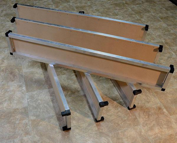
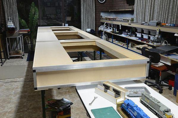
Then some side panels.  These are made from Cubelok fittings and 25 mm RHS aluminium.


PE 03

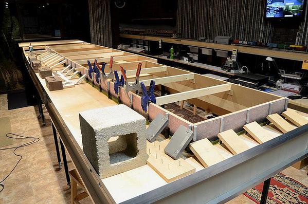
3 mm MDF is glued and riveted on to the frames, making them very stiff, strong trusses.


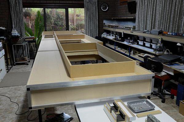
The trusses are then joined together to make the tops for the three modules.


PE 04

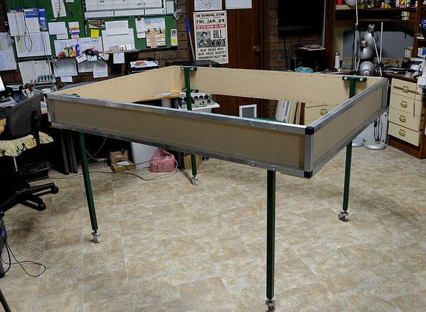
And then the legs are added.


PE 05

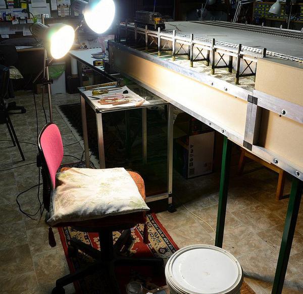
The three modules are then bolted together.


PE 06

Each module is 1.2 metres (47 inches), by 1.7 metres (67 inches), when they are bolted together they make a layout 1.2 x 5.1 metres (16'9").  I hope my conversions are correct. 


The left side is set aside to be the sea.


PE 08

300 mm ( 1 foot), is allowed for the boat.


PE 10

And bearers are installed which will carry the sea walls.


I'll upload this so far to see if I have been successful, and also to see if anyone is interested. 


Cheers

Attachments

Images (9)
  • Amster 06
  • PE 01
  • PE 02
  • PE 03
  • PE 04
  • PE 05
  • PE 06
  • PE 08
  • PE 10
Last edited by MaxSouthOz
Original Post

Replies sorted oldest to newest

Thank you!


Next, I turned the modules over.


PE 11

And added the gussets and the blocks which will carry the curtain spring wires.


PE 12

and support blocks for the cross beams.


PE 13

Back up the right way, adding the noggins.


PE 14

Now I'm adding the sea areas, using 3 mm MDF.


PE 15

Now the 16 mm MDF sea walls.


PE 17

Which are covered with Scalescenes paper brick and other effects.  They download as HO, but when I printed them, I changed the settings to 200%.


PE 18

The walls were masked off and sprayed with matt black from a rattle can.  Then neat PVA was spread along the bottom and Woodlands Scenics Fine Turf Burnt Grass was blown on to it from a piece of folded card.


PE 19

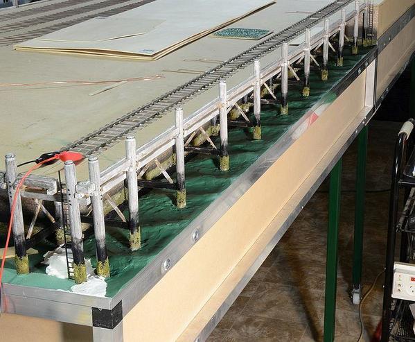
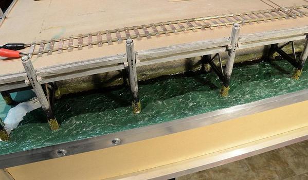
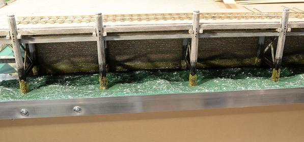
Then I took some 1/2 inch Meranti dowel and scratched it with an Olfa 450 draw knife to simulate cracks in the piles.  My reference photos show piles to be a light grey colour, so I painted them white and washed them with black until they looked right.  Then I painted the bottoms to the same height as the matt black on the walls; then rubbing isopropyl alcohol into the top of the black paint to dissolve it and make a transition.


PE 20

Adding more Fine Turf Burnt grass over PVA.


That's the photo you saw on the other thread.


Are you still with me?


Cheers

Attachments

Images (9)
  • PE 11
  • PE 12
  • PE 13
  • PE 14
  • PE 15
  • PE 17
  • PE 18
  • PE 19
  • PE 20
Last edited by MaxSouthOz

Thanks.


I've built several layouts using that system.  I don't have a way of weighing them, but I can lift them individually OK.  The main thing is that they don't twist or move.  When I get the track on them it stays put.


When I sold my other layouts, they were easy to transport in modules.


It's a pleasure.


It's only 9 pm here, so I'll put up a few more pickies in a minute.


Cheers


OK  On we go . . .


PE 21

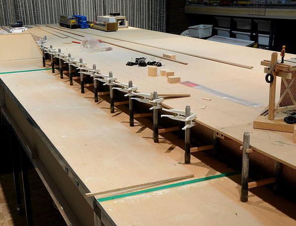
Here's the inside row of piles.  I made the joins in the brickwork line up so the piles are in front of them.  Lots of lateral thinking with the clamps and braces - including a couple of old laptop batteries. 


PE 22

There will be 39 bents.


PE 23

Looks OK.


PE 24

So now there is a new row of piles to be made with hoops on the tops.  40 of these because the last one is against the wall by the slipway.


PE 25

The other side.


PE 27

The outer edge has 25 x 25 mm angle aluminium which has been trimmed down with the multi-tool so that the "sea" will only be 6 mm deep.  Sorry about the metrics.


PE 29

The whole of the top deck has now been secured and the slipway has been clad.


PE 30

I made a mock up of the proposed construction of the bents, which you can see on the right.  Work is progressing.


PE 31

That's a better shot.


PE 32


All of the 39 bents are done.  Phew!

Attachments

Images (10)
  • PE 21
  • PE 22
  • PE 23
  • PE 24
  • PE 25
  • PE 27
  • PE 29
  • PE 30
  • PE 31
  • PE 32

Max,  I think I have the same boat kit. Mine is a Artesania Latina model 20201 AMSTERDAM ocean tug boat. It is 1:50 scale with a length of 1060 mm = 41 3/4 inches. I bought a Radio Control set for it too. 


Like you, I too have not finished building it. I stopped when I had to drill into the plastic hull for the drive shaft to the prop. That was 2 years ago!!!! Do you know if and where ballast weights should be placed in the hull? I think I should install them prior to installing the electric motor mount. I did get all the superstructure completed. Have to finish the build.


Your layout modules look expertly designed and built. And your sea wall and dock area is very impressive.


Paul Goodness

Max,


This is is very impressive. Your clean photos and descriptions make everything look and seem so effortless (!) and I love your attention to detail and precise execution.


I've been researching the intersection of Pittsburgh, PA river tug boats, barges, and railroads and will follow your progress with great interest.


Thanks for posting.


Tomlinson Run Railroad

Thanks, guys.


Paul, I rescued the kit half built and pulled it apart and then rebuilt it to where you see it.  Yes, it's same Amsterdam.  I've got the motor in, but I still have to cut the hull for the bow thruster.  Bow thruster?  You can tell I'd be drummed out of the proto club. 


With regard to the ballast, I figure I'm going to get it built and then use small bags of shot placed around the inside, while it's floating in my bath tub; to get it to sit on its marks.


Meanwhile, it will be a front drop for my railroad.


It's after midnight here, so I'll post some more of the story tomorrow.


Cheers
Now for a bit of a trip around the wharf.


PE 33

Here's the bottom of where the slipway will be.


PE 34

I've started to cut in for the ladders.


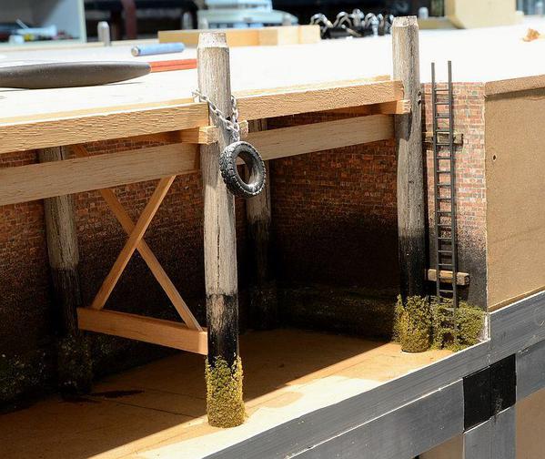
PE 35

The tyres are from Don Mills.  I pushed a Peco track pin up from inside and bent it over to make a hook.  The chain is cheap jewellery chain from the Op Shop where Wendy volunteers once a week.  I sprayed it with grey etch primer.


I painted the oak beams with several coats of water to make the grain stand up.  It's a trick I learned from an old French Polisher.


PE 36


PE 37

The timbers are from the local hardware store.  They carry lots of small sections for trimming.
 

I try to model from reference photos.  Here's one sent to me by a friend in Vancouver, taken on a recent sailing trip on his boat.


Refuge Cove Store - John Dew

It's been one of my most valuable reference shots.  Most of the timber here is Cedar (I know- what a waste, but they have plenty of it).  However, you can see how white timber becomes after a while in the elements, if it's not treated.


I also have reference photos of local wharves which also show the same whitening.


PE 39

So I began by painting the timber with Golden paints Titanium white, and then washed it with a thin black wash until it looked right.  It's hard to get an accurate shot as I had to light underneath with extra lamps.


PE 40

This should show the process a bit better.  I have a range of track pins with various sized heads, which I used for the "bolts."    I didn't bother putting bolts in the ties at the bottom, as you can't see them for the black paint.  The hoops are circles of copper wire soldered and painted.


PE 41

Because I still have an HO brain, I keep going back and checking the context to make sure that it still looks "right."


PE 42

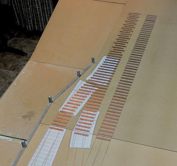
This layout plan will be John Allen's "Timesaver."  Because the table is only 5.1 metres (16'6"), long it will provide hours of shunting fun.  The centre module will have all of the turnouts, so I've made paper templates using the Templot software developed by my friend Martin Wynne; ready to start building.


PE 45

Module one has the three head shunts.  The straight ahead one may possibly continue a bit further into the hinterland behind the docks, but the others will stop short.   They are in the form of a gauntlet (sometimes known as a gantlet).


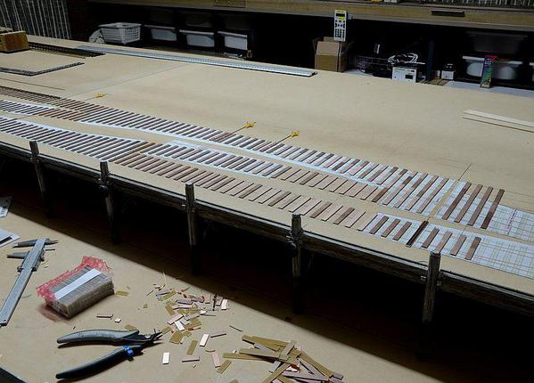
The ties are PCB cut specially for me by a firm in Melbourne and are scale 9'6" x 12"  As the whole of the wharf area will be paved, there is no need for details to be added.  On the other side of the layout, there will be a track running the full length of the board.


Because the layout will also be able to be computer controlled by Railroad & Co software, I need a Profiling Track.  That consists of at least three contiguous Blocks, the middle one being at least a metre long.  At least half of that track will be able to be detailed.  That should be enjoyable.


Back later, after breakfast.


Pay attention up the back, there will be a quiz later. 


Cheers

Attachments

Images (11)
  • PE 33
  • PE 34
  • PE 35
  • PE 36
  • PE 37
  • Refuge Cove Store - John Dew
  • PE 39
  • PE 40
  • PE 41
  • PE 42
  • PE 45

I'd better finish it off and bring it up to date or I'll lose track of where I was. 


The last section is about installing the tugboat into the base board.


PE 43

First the hull is covered with cling wrap.  Then newspaper is laid up using PVA al la mode papier mache.


PE 44


About five layers of newspaper, then a lattice work of cereal box cut into strips, then about another five layers of newspaper.


PE 46

The mould is then laid on the baseboard for marking out.  A 6mm keelson has been glued on for stiffening - and for support underneath.


PE 47

The base board is cut out using the multi-tool shown before.  The boat is inserted and the mould is glued in place using PVA.


PE 48

The underside bracing supports it from below.


PE 49

The outside edges of the mould are painted with the same antifouling colour as the hull.  There was some over-spray, so I went a bit crazy. 


PE 50

Now the boat sits in place.  The line at the top of the mould marks the top level of the "water." 


That brings us up to date after three months of working on it.


I hope you've enjoyed the ride.


I've matched the sea bottom colour to my reference photos and now I'm researching realistic water effects.  I'll be back when I've made a breakthrough. 


Cheers
Attachments

Images (7)
  • PE 43
  • PE 44
  • PE 46
  • PE 47
  • PE 48
  • PE 49
  • PE 50

Inspiring! I'm really enjoying your thread, especially making the boat removable. Please keep posting pictures.


I also just wanted to share my model ship ballasting experience.  For some smaller models, I used modeling clay molded it into the bottom of the hull and then pushed the lead shot or other weights into it.  I did a good job of keeping the weight where I placed it.

Thanks IHM


Thanks for the tip on the modelling clay.  It all helps. 


Here's one of my reference shots for the water . . .


Front of PS resized

I've watched about a hundred videos and scoured dozens of threads elsewhere, but I haven't yet been able to replicate it.


The challenge is the rows of swells.  I've marked them in this next photo.


Front of PS resized

My wife Wendy, is an artist so her studio is an Alladin's cave of stuff to play with.  I've tried gesso, acrylic gel medium, Mod Podge, PVA, you name it. 


My next test board will have the swells built on to the board first, then PVA or Mod Podge for the wavelets.  I know that it's not prototypical - but it might be the answer.


I'll post a photo.


Cheers

Attachments

Images (2)
  • Front of PS resized
  • Front of PS resized

I've had a lot of luck using Mod Podge to paint on waves. I haven't tried anything with as much relief as you are looking for, but I don't see why it wouldn't work.


Also, are you familiar with the work of the Sweedish modeler (and painter) Troels Kirk? He is the master of ocean water, and has documented his methods thoroughly.  Do a search for "Coast Line RR"

Great job!

Layout is aw-sum.

Please keep posting as you go the scenery and building are top notch.

Love the boat as I m into scale RC scale steamboats and electrics.

Great idea to use the boat with the layout and to have it ready for RC use in a pool/pond.

As far as ballast, I always use the large battery (that will fit) for ballast then trim with lead.

Bow trusters work great. On my steam I use a kitchen rudder for reversing and idling.

KEEP POSTING.


Thanks, Guys.  Most appreciated.


The problem I have with PVA (and Mod Podge - which is PVA based), Pete - is the bubbles.  If I heap it up to make the swells, the white bits finally set up with bubbles trapped in it - part of the drying out process.


So I'm going to make the swells first - probably out of plaster, and see how that goes.


I think I've seen Troels Kirk's work, but I'll do another search and see if I can steal some of his ideas. 


Cheers

Kitchen Rudder: invented in the early 20th century by John G.A.Kitchen of Lancashire, England. It turns the rudder into a directional thruster, and allows the engine to maintain constant revolutions and direction of drive shaft rotation while altering thrust by use of a control which directs thrust forward or aft. Only the rudder pivots; the propeller itself is on a fixed shaft and does not.                                                          https://en.wikipedia.org/wiki/Kitchen_rudder

I use two servos, one to turn right and left and the other to open and close the rudder. The boat can turn in it;s own length and can steer going in reverse with a single screw. Unfortunately the steam launch is 36 inch long with a 12 inch beam and the scale is 1/12

If uou are interseted I can take a picture of the rudder from the back and inside where the servos are connected. The boat is all scratch built including the boiler and engine.

OK  I've watched Troels' video a multiplazillion times since breakfast. 


Thanks again for the heads up, Pete. 


I just happen to have one of those nifty trowels in stock and I've been able to source the Liquitex Gloss Super Heavy Gel from my wife's art supplier.  The excellent news is that it is on special if I buy on line - which I did.  A$35.00 for 950 ml. 


What was evident as well is that if I want to incorporate swells into it, I'll have to contour the bottom.  It's cheating and very "non-proto" but if it works . . .


Now to make a test box.  I'll post the pickies as I go.


Cheers
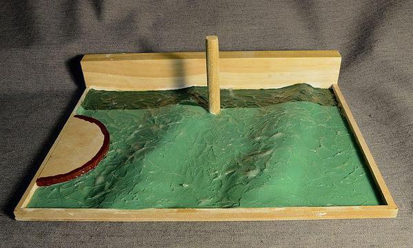
Test box.


PE 52

The dams at the side are 6 mm (the same as the layout), and the semicircular one represents the stern of the boat.


PE 53

We have a product in Oz called Gyprock.


https://www.google.com.au/sear...cUVriHAsa30gS5jpyYDw


I think that it's called dry wall in the US.  Well, I've got a tub of the jointing paste which I use for land forms (and now water forms), which I've used to create the swells.


Once its set up, it can be carved and sanded very easily.


When it dries, I'll finish shaping it and then paint it with the bottom colours.


The gel should have arrived by then. 

Attachments

Images (2)
  • PE 52
  • PE 53
Originally Posted by MaxSouthOz:

Here's one of my reference shots for the water . . .


I've watched about a hundred videos and scoured dozens of threads elsewhere, but I haven't yet been able to replicate it.


The challenge is the rows of swells.  I've marked them in this next photo.


Front of PS resized

My wife Wendy, is an artist so her studio is an Alladin's cave of stuff to play with.  I've tried gesso, acrylic gel medium, Mod Podge, PVA, you name it. 


My next test board will have the swells built on to the board first, then PVA or Mod Podge for the wavelets.  I know that it's not prototypical - but it might be the answer.


I'll post a photo.


Cheers
This is the effect we got at my club using heavy duty aluminum foil. We crumpled it up and then spread it out flat. After paint and varnish we drybrushed some of the peaks white. Don't know about the swells though.


IMG_1008

Attachments

Images (1)
  • IMG_1008
Last edited by Pat Kn

Max,   Thank you for posting the photo of your tug boat motor mounting. It is very helpful. I was thinking of using pieces of re-bar rod for ballast held in place with silicone caulking. I just have to get up the nerve to drill that hole in the hull for the drive shaft.


Very clever paper-mache support for the hull. Nice way to hold it at the water line. Your work is inspirational. 


Paul Goodness

Thanks, Paul.


You will need a lot of weight to get her to sit on her marks.  A couple of guys in our club have built Amsterdams and I think they said they needed 7 kg.  If that's the case, steel won't cut it.  We'll need lead - or gold!  Maybe lead. 


That's one of the reasons I've gone for the big gel battery.


Cheers

Last edited by MaxSouthOz

I tried to photograph the plaster waves before I painted them, but no dice.


Too much reflection.


Here they are after painting . . .


PE 56

Even then I've had to heavily side light the tray to get any sort of shot.


Also, now I can see all of the blemishes I couldn't see before.  Lesson: Side light the plaster when sanding it.


It's very soft and easy to sand - indeed the final smoothing was done with just my finger.  Now I'm set for a life of crime - no fingerprints! 


The gel should arrive tomorrow, so we'll see what kind of a fist I've made of it.


Cheers

Attachments

Images (1)
  • PE 56

I wasn't happy with Troel's result using the palette knife, so I tried a teaspoon.


I'm not happy with that, either so I'm going to try some other applicators.


Here's the spoon results . . .


aaaa

It's not quite been 24 hours, so there are still some milky bits; but it doesn't look very convincing.


One thing that I'm very happy with is the way the small plaster blemishes have been hidden.


Onwards and upwards.


Cheers

Attachments

Images (1)
  • aaaa
Last edited by MaxSouthOz

In the spirit of constructive suggestions:

1) I think I would try more subtle swells--to my eye, the waves should carry more of the visual effect, and the swells should be less prominent. 

2) I think the green is too green and too uniform. I would try a very flat camo green and stipple it with a little camo brown.

3) I would try a much thicker layer of acrylic gel. Will take a long time to dry, but it will give you more to work with when sculpting the waves.


I'm really excited about your project.  Please don't take any of this as criticism -- just a few thoughts.

Thanks for your thoughts, Pete.


I'm working with reference photos of my local area, so I'm very sure of the look that I'm after.  If you go back through the thread to the photos, you will see what I mean.  I plan to reduce the troughs when I start in earnest, because I agree that they are still too deep.


The colour is affected by the gel.  It doesn't look the same as when it is au natural.  I agree as well that I should grey it down a bit.  I don't want a blotchy bottom, as the docks area here is a plain sandy bottom.  It needs to be more like the reference photos.  But I'm getting closer. 


Dragging any kind of tool around in the gel like Troel and I have done so far, makes lines rather than wavelets.  This time I've tried dipping my finger into the gel and stamping blobs of gel on to the sample.  It pulls the gel upwards as the finger is removed, leaving more of a point.


The gel also slumps like PVA does, but not to the same extent, so I'm hoping for some nice wavelets.  It takes more than 24 hours to set up now.  I'm applying about 2 mm.


One thing I have noticed; I can get the knife/spoon/finger to slide across the gel as it sets up much better if I wet it first.


I appreciate your interest. 


Cheers

Thanks, Guys.


I'll certainly look at those tools, Carl.


I've got two areas to attack.


Firstly, the gel has made the green look wrong.  Easy to fix.


Second, the gel surprisingly slumps as it sets up, - more than I thought that it would - leaving strings rather than wavelets.  I think Pete is on to something.  I might need to push the gel into thicker shapes.


I've got about 2 square metres of sea to do, so I want to experiment with small samples until I have the process worked out.  Then I can launch into it with confidence.


All good fun.


Cheers

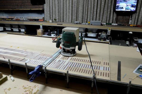
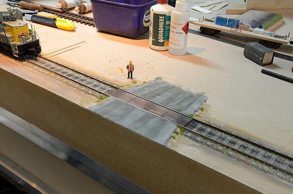
All of the ties have been glued on to the centre module, which is where all of the turnouts are located.  Throwbars, trunking, rodding, cranks and servos have been installed.


The servo centering device is vital to get everything centred in the drive trains of the turnouts.


004


Now to lay the ties for the end module.

Attachments

Images (1)
  • 004

Well, I've tried using thicker shapes and ended up with ugly pointy waves and some accidental voids.  It's been two days and the gel still hasn't set up completely.


I went back and watched Troel's movie again for the umpty-ninth time and one thing he did stress was to keep the gel thin.  I'm currently working on a way to stamp it to pull up the wavelet shapes.  I'm thinking something like the butt end of a pencil.


I've started remixing the paint and it's looking better, as well.  I'll post up a photo later today.


In the meantime, the ties continue to march along the docks.


Cheers

I need to keep taking breaks from laying the ties, as it's killing my back. 


So during the breaks, I've been playing with the water effects.


PE 61

I've had to Photoshop it to get the colour close to the naked eye look.  It's not easy to photograph.  Anyway, the photo looks similar.


I'm happy with the wavelets.  Thin gel and the but end of a pencil to stamp them.  There are still some that haven't finished setting up, but you get the idea.

Attachments

Images (1)
  • PE 61

To me eye, it appears that shower door glass with the swells then detailed on top would create the effect of your reference photo.


But, the pilings and bulkhead pose a problem.


After looking at this thread on water effects, I would suggest a product from the U.S. that appears to achieve the effect is called Enviro-Tex and Envirotex-Lite. Seems like 12 thin coats are needed.

Last edited by Moonman

Hi Carl.


Thanks for the thought, but as you say, the shower glass idea won't work because of the logisitics of trying to fit it to the layout.  I'm dealing with a couple of square metres here - with all of the piles already in place.


The examples in the link are all excellent, but don't fit the waterfront scene I'm building.


The gel is working really well now - using a single thin coat.  One of the problems with PVA based water effects is that small bubbles become trapped in it, ruining the effect.  The gel never traps any bubbles, and now I've worked out how to make convincing wavelets, my problems seem to be over.


Thanks for your interest.

I'm away for a week with the band, doing a music festival in NSW, so this will be the last post until I'm back.


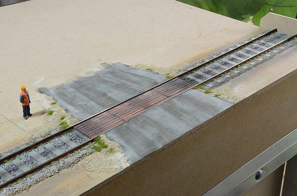
The right hand side road will be a Profiling track for Railroad & Co software, so it's pretty much just a straight run.  The ties have all been laid.  Phew!


PE 63


Next step is to install the Block detectors and bus.  I'll be using Lenz LB 101 Block detectors and LR 101 feedback modules.  I could run the locos straight off the bus, but I have to put the detectors in later anyway, so I may as well do them now.


Also, I now have a grip on what I want to do with the water.


All that is for next week; meanwhile we must tend to the needs of our "Adoring Few."  


Cheers

Attachments

Images (1)
  • PE 63

I reckon that the most important thing to get right for a big job like this is to be comfortable, with all of your resources within easy reach.


PE 69


Here's a closer view of the wave forms.


PE 70


It's only the first pass, but it's showing the way it's going to shape up.


The white dots aren't splashes.  They're small yellow dots which represent mussels.


In the next pass, I'll be able to smooth out the surface and sculpt in some extra swells if I need them.

Attachments

Images (2)
  • PE 69
  • PE 70

The gel as been on for four days and is nearly completely set.


PE 75

The Liquitex gel shrinks as it sets, as do all of the others I've tried.  That causes the wavelets to morph into flat areas, bordered by raised lines.


It shrinks so much that it pulled the paint off the top of the aluminium edging, and I had to repaint it.


I plan to detail some fresh wavelets with individual dobs of gel where they appear in my reference photos.


The gel has greyed off the green colour to a much better hue, and the gloss varnish will improve it further.


I'm not unhappy with it so far.

Attachments

Images (1)
  • PE 75
Last edited by MaxSouthOz

Thanks, Tom.

The piles are painted with Golden brand Titanium White, then a black wash is applied in several coats until I like the result.

Using several coats of black wash gives a nice uneven range of effects.  The bottom of the piles is straight black acrylic which is rubbed at the top of the black with isopropyl alcohol to fade it a bit.

The barnacles are Woodlands Scenics Fine Turf colours of Burnt Grass, Green Grass and Yellow Grass.  After painting the piles, I painted neat PVA around the bottom and then sprinkled the Fine Turf on before the piles were installed.  Most of the colour is Burnt Grass.

Cheers

With the speed of a retarded glacier, the track laying creeps towards the end of the plank . . .

PE 84

All of the ties have been divided and the continuity is correct.

This is the main intersection where four of the turnouts are close coupled.

The next job is to install the Tam Valley servo controllers and see if any of the point rails will move. 

Attachments

Images (1)
  • PE 84
MaxSouthOz posted:

Thanks, Andre.

The ties are made from printed circuit board (PCB), with the rails soldered to it.  It's necessary to cut the copper on top of the ties so that there is no connection between the two rails.  I use a Dremel to make the cuts.

Cheers

Oh ok, because the line look like all the way down even over the roadbed.

When I made my turnout and crossover, the best part was making and aligning frogs.

AG.


Add Reply

Post

OGR Publishing, Inc., 1310 Eastside Centre Ct, Suite 6, Mountain Home, AR 72653
800-980-OGRR (6477)
www.ogaugerr.com

×
×
×
×
Link copied to your clipboard.
×
×