Question for DaleH , gunrunnerjohn or other Forum members knowledgeable on the power dropout over diamond crossover and short and long term effect on locomotive electronic boards.


I have three 45 degree and three 22.5 degree diamond crossovers in series at different locations on a large layout I am building, the frogs are plastic, given the varying centers of the locomotive power pickup rollers, there are momentary power losses as the locomotives travel across the diamond crossover, are these momentary make and break contacts of the roller pickups creating electrical spikes that are damaging to the electronic boards?


If so, would it be possible to install a capacitor on the outboard side of the power control board to eliminate these momentary power losses.


Locomotives have dc can motors maximum voltage 18 to 20 volts AC.


I do not see any possible way to modify these diamond crossovers to prevent this momentary power dropout.


Thanks for your responses in advance to my concern. 


Last edited by John Ochab
Original Post

Replies sorted oldest to newest

I visited Atlas"O"s web site and see what you mean. Not an easy fix. It would some work.  You could replace the plastic with metal rail . Maybe buy a 10 inch  section for rail. , If you have a dremel , soldering gun . CA (crazy glue) I'm sure  you could come up with something.it's doable . I don't know what other options are available? Put a set of rollers on the first  car behind  the engine and tether it. (1 wire)?

Another forum member ran into this with Ross 45's. Those have plastic on the outside rails. The trucks of his engine would sit on both insulated pieces of the diamonds.


Spreading the 45's further apart would allow a collector to be on a hot rail while the was on the diamond. A 5.5 + 1.25 in between will keep a roller on a hot rail.


The older version sounds like the solution. Then you could make the diamond hot.


I don't know if it would be safe putting a capacitor in the engine to hold momentary power. It would need to be a large one.


Hi John,

I am having there same problem as well as significant

sparking on certain cars as they traverse the diamond with my

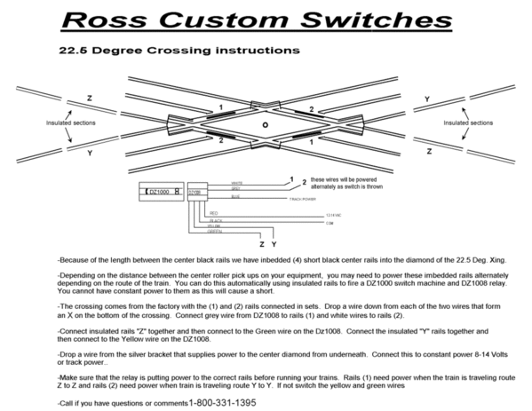
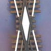
Atlas 22 degree crossover. Ross Custom Switches offers a

drop in replacement with a hot diamond and 4 embedded helper

rails you can relay power to. In spite of my crossover already

ballasted in place, I think the track gang will be getting a

work order to replace the current crossover. 


22deg


22small


Hope this helps, Mike

Attachments

Images (2)
  • 22deg
  • 22small

We hot wired our Ross crossing thinking it was the pickups, turned out to be loosing common instead. "Grounded all the outer rails and the issues disappeared. Removed relays after. Don't have any locos where the roller spacing is exactly that distance, now would either get triple pick up or add wire from tender.

The Atlas one is not an easy fix because the X part is plastic . It's not a solid diamond. I don't know if you could place a solid  metal wire over the plastic rail and somehow fasten it. Dill a hole at each end of the rail  and stick the solid wire down through almost like a large packaging   staple.   Twist together below and wire...??

Here is a possible solution I drew up for the Ross double switch crossover


LINK


The stationary crossover would be much simpler. All you need is one,SPDT relay and an outside insulated rail to one approach of the crossover. The 2 #1 rails would go to a NC contact,the 2  #2 rails would go to the NO contact. The common contact would go the the transformer power. Either rails set one one or rails set two could be powered but not both. The insulated outside rail on one approach could power the relay coil and orient the relay contacts so no short would occur on the rollers. If this is not clear I will draw a diagram. 


Dale H

Last edited by Dale H

This posting concerned three back-to-back 45 degree crossovers, one straight through track with three tracks crossing over the straight track.


To resolve this power dropout issue, I purchased 1/8 inch square K & S Metals brass stock, mitered and cut 6 lengths to match the existing 3 plastic diamonds. Placed the individual brass cut lengths in the work bench vise, milled a 1/16 inch by 1/8 inch 45 degree slot in each length at mid length. Soldered 2 lengths together to form 3 replacement brass diamonds, on the outside on one leg/diamond I soldered a 12 inch long # 18 gauge solid insulated wire for track powering of these diamonds using a 3PDT toggle switch.


Removed the three plastic diamonds, using Gorilla Super Glue glued a .040 inch thick Plastruct plastic flat stock shim strips to the crossover base plastic ties, then glued the replacement brass diamond to this shim. I let this glue setup over night, drilled on hole per diamond in the plywood deck to route the diamond power wire below the train board.


Using wire nuts and # 18 gauge wire temporarily wired this junction no issues with locomotives stopping with the powered diamonds.


Last edited by John Ochab

Darian,


I have no pictures of the brass diamonds, what I did was to use the plastic diamond as a template and made a drawing of this template. Once the drawing was made, I cut the 1/8 inch square brass bar stock, 2 pieces, and mitered both ends to match the plastic diamond, allow sufficient length for mitering.


The next set is the most difficult, mark the midlength of each bar, clamp this brass bar in a machinists(bench vise) and use the edge thickness 1/8 inch of a rectangular steel file, hand file a diagonal slot 1/16 inch deep by 1/8 inch wide, this slot must be parallel to the mitered ends of this bar. Likewise, on the other bar, hand file a diagonal slot, 1/16 inch deep by 1/8 inch wide, this slot must be parallel to the mitered ends and note on the opposite side of the first bar. Once both bars are cut to length,ends mitered and the diagonal slot at midlength hand filed, interlock both bars at midlength, there combined thickness at the midlength slot is 1/8 inch.


Over lay this brass diamond on the plastic diamond, the important dimensions are the mitered ends of the brass bars and the plastic bars, to long or a skewed miter angle can cause wheel flange interference as the car/locomotive axles pass over this diamond. Hand file,as required, the brass bars for this clearance. Once satisfied, hold this brass diamond assembly together on the mitered ends using mini-clamps or pliers to maintain the correct angularity and flatness at the mid-length slots. I used a 200 watt soldering gun, flux and electrical solder to solder both bars together at mid length. Overlay the soldered brass diamond on the plastic diamond, if the overlay is a good match does not have to be perfect, then solder a 12 inch long 18 gauge wire one leg of this brass diamond for powering. If the angularity is off, reheat the soldered joint to the solder melting point, reset angularity, resolder and check by overlay, then solder the power wire to one leg.

Caution, when soldering the brass diamond, the soldered assembly becomes very hot, air cool before handling.


Once the brass diamond and powering wire are complete, remove the plastic diamond down to the base(top) of the plastic tie, I used .040 thick by 1/8 inch wide plastic styrene strip as a shim between the base of the brass diamond and the top of the plastic ties. I used Gorilla Super Glue to glue the styrene strip to the top of the ties, let the glue setup, centered the brass diamond for the straight and diagonal center rails and glued the brass diamond to the styrene strip.Let the glue setup over night, checked wheel flange clearance on mitered ends, if wheel flange interference is possible, use miniature file/standard file to open up the clearance by filing the appropriate end(s) of the brass diamond mitered bar ends. Drill a hole through train board for pulling the diamond power wire below the train board.


Last edited by John Ochab

Darian,


If you need additional information go to my personal profile, my e-mail address is listed there, when removing the plastic diamond, I used a wire cutting pliers, put the jaws of the pliers at the base(plastic tie level), close the the pliers, rotate sideways the closed pliers left to right, this will snap off the plastic. Clean up the remaining plastic with an Exacto knive with the chisel cutting blade(3/16-1/4 inch wide), use a good light, and keep your fingers away from this blade at this cleanup in case the blade slips. You should have a level surface before gluing down the plastic shim strips.

Last edited by John Ochab

Add Reply

Post

OGR Publishing, Inc., 1310 Eastside Centre Ct, Suite 6, Mountain Home, AR 72653
800-980-OGRR (6477)
www.ogaugerr.com

×
×
×
×
Link copied to your clipboard.
×
×