The Prototype - Background & History

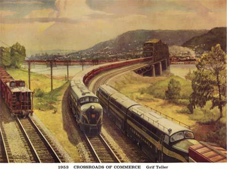
This layout is my attempt to model the 7 miles of the PRR Panhandle that ran through the northern panhandle of West Virginia and Steubenville, OH. The Panhandle was a second mainline of the Pennsylvania Railroad that ran from Pittsburgh to St. Louis.  It existed from 1848 through 1995.  Grif Teller immortalized the double track bridge across the Ohio River in the painting “Crossroads of Commerce” which appeared in the 1953 Pennsylvania Railroad Calendar.  That bridge still stands and the track using it serves Weirton Steel (now Arcelor Mittal) and the brick refractories and businesses on the New Cumberland secondary.  Unfortunately from Weirton Junction through Burgettstown and points east, the track has been pulled up and the right of way has been converted to a hiking / bike trail.


1953


I grew up in Weirton, WV in the 1950s & 1960s. I left in 1978, but still have family and other ties in the area. The PRR double-track bridge at MP 42.11 was always a source of fascination for me, even as a small child going to Steubenville with my parents and grandparents. However, it was not until I saw Teller’s painting (in the late 1990s) that I realized what I wanted to model.

Vital Statistics of the Layout:

  • Size & Shape: Folded dog bone - 8.5’ x 18.5’ x 10’ x 18.5’ – approximately 180 square feet.  There is an 8.5’x 5’ hidden storage yard under the western end.
  • Track:  Mostly GarGraves with some Curtis sectional curves, Curtis Hi-Rail turnouts, and a few Ross Custom Switch turnouts.
  • Yards: Weirton Junction, Weirton Steel, Coal Mine Spur, Hidden Storage
  • Command System: TMCC. Turnouts have Z-Stuff DZ-2500A & C switch machines and are both TMCC and pushbutton controlled.
  • Wiring & Blocking: 8 power districts are supplied from 2 power distribution panels. Home run wiring has been used.
  • Power: 2 Lionel 180 watt PowerHouses supply all track power to districts 1-8. Two (2) K-Line PowerChief 120 transformers power switch machines, lights, and some AC accessories.  All DC accessories, building lights, traffic signals and street lights get their power from various 3VDC, 5VDC, and 12VDC power supplies.
  • Signals: Z-Stuff DZ-1060 PRR position signals (4) & MTH PRR signal bridges (2).  The layout is only signaled for travel in the counter-clockwise direction.


Track Plan:


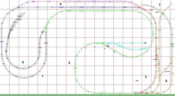
Districts are numbered and shown in their colors:


1 - Steubenville BLUE

2 - PRR Bridge & Weirton LT GREEN

3 - Weirton RED

4 - Hidden Passing Siding MAGENTA

5 - Coal Mine Spur BLACK

6 - Weirton Junction LT BLUE

7 - Hidden Storage Yard GREEN

8 - Weirton Steel Yard YELLOW


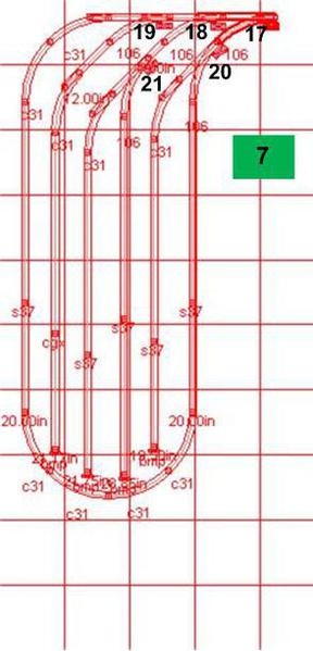
v226 PRR Panhandle Track Plan - Annotatedv226 PRR Panhandle - Hidden Storage Yard


Hidden Storage Yard:

This yard is reached by a long yard lead below the rear of the layout.  Storage is available for approximately 40 cars on 4 stub tracks.  A balloon track is available for turning trains.  The yard will permit Weirton Steel to accept arriving deliveries (coal, ore, empties) and ship product (coils, boxcars, empties).


Features of the Layout’s Western End:

Steubenville, Ohio dominates the western end of the layout. The center of the action is the intersection of Fourth and Market Streets. Fourth Street runs roughly east to west. Market Street will contain some of the nicer businesses, including a 5 story building. The west end of Fourth Street will be the "wrong" side of the tracks. There will be a seedy hotel and other run-down structures in this area.

The PRR station will be at the south end of town with the platform between the spur and mainline.

The coal mine and tipple just north of Steubenville supplies coal for Weirton Steel. The 2-track tipple can load approximately 4 cars at a time. The tipple spurs have been extended by several inches to accommodate track bumpers. A curved #6 Curtis switch allows the spurs to bend around towards the northeast. These tracks sit (level) on top of a plateau about 1.5” above Steubenville (behind Market Street). The coal mine is reached by a trailing point spur that allows coal trains to be backed all the way up to the tipple. The spur is protected by a Pennsy 3-position signal head.

The Gould No. 5 tunnel passes under the coal mine and exits just before reaching the Ohio River Bridge. Within the tunnel, a turnout connects to the hidden passing track that runs behind the screen and river bridge. This hidden track allows trains to cross the river without being seen.


Features of the Layout’s Eastern End:

The dual-track bridge is 7’ long and was supplied by East Coast Enterprises.  Originally, I had planned to build the bridge myself, but it proved impractical time-wise as well as prohibitively expensive.  I erected a temporary bridge that held a Curtis double cross-over, but I removed that when the permanent bridge was installed.  The bridge is protected on both ends by a pair of MTH PRR double-head signal bridges.  The southernmost track is for eastbound traffic, while the other (northern) serves westbound movements. East of the bridge (as the track loops back on itself and moves west) is Weirton Junction.


Stubenville 2 Track 84 Inch [14)


Weirton Junction is protected by a Pennsy 3-position signal head and will eventually sport a replica of the prototype WC PRR Interlocking Tower.  One track will be designated as Standard Slag, allowing Lionel and MTH slag cars to park here and discharge their slag loads. These tracks will also serve as an engine pocket for the WSX Alco S-2 switcher as it moves ore car cuts in and out of Weirton Steel. The track may also end up storing cabin cars.


 DSCN0030


The city of Weirton will be the center of the layout’s eastern region. Depiction of the city will focus on the appearance of North Weirton in the 1950’s. The Green Mill Restaurant (although it existed as a family business during the 1920’s and 1930’s) will be located here, just across Main Street from Gate No. 1. The mill wall will parallel Main Street to the intersection of County Road and Pennsylvania Avenue.


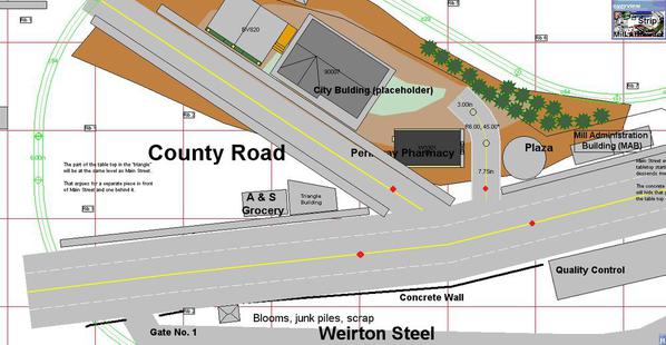
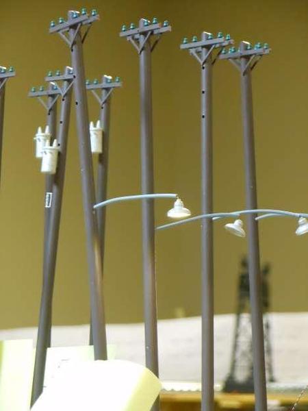
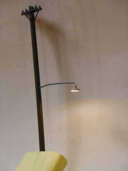
Downtown (North) Weirton at the intersection of Main Street, County Road, and Pennsylvania Avenue will feature several unique structures - the Triangle Building, Weirton Steel's Mill Administration Building (MAB), the Quality Control Lab (QCL), and the Honor Roll (a memorial for members of the armed services).  Working traffic lights will control the intersection and lighted telephone poles will illuminate the streets throughout the downtown area.


 NorthWeirton- with Lights


At Crawford's Crossing, Main Street will ascend a highway overpass bridge over the steel mill yard, just as in the prototype.


Weirton Steel:

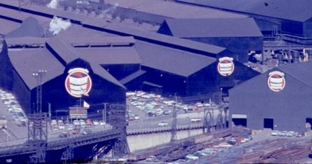
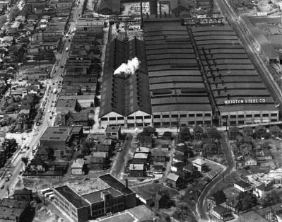
Another major feature of the layout is Weirton Steel. The company’s mills are located against the eastern wall of the layout. The steel mills fit into the wall at a 30 degree angle. Mill buildings and items considered for this area are (south to north):

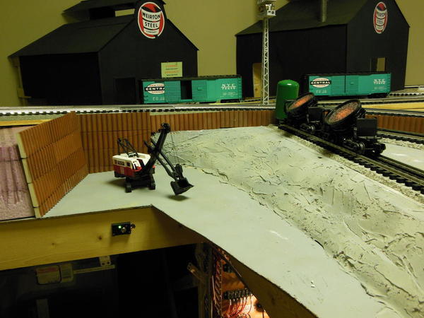
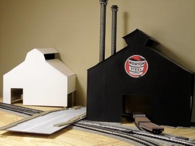
  • Open Hearth: This mill has 2 industrial smokestacks. Ingot (flat) cars will move in and out of this mill. This building will disguise a descending spur to the hidden storage yard. (Built)
  • Blooming Mill: This will also be a vertical channel black steel building with a WSX Logo on front. A billboard will be placed on the front. A raised transformer platform will sit at the side of the mill. (Built)
  • Strip Steel: This will be the largest of the mill buildings and will have a spur running into it. The spur will be used to bring in empty gondolas (exit with pipe and coil loads). (Under construction)

Other structures that will be part of the mill will be a tank storage structure, floodlight towers, and a coil yard.


BLM2 002


Operational Goals:

The PRR Panhandle was developed with the following operational goals in mind:

  • Allow the simultaneous operation of at least 2 trains on the mainline and 2 switchers in yards or spurs.
  • Use a signaling system that prevents collisions.
  • Have curves large enough to permit the use of 72’ scale heavyweight passenger cars (requires at least O42).
  • Allow the use of medium-sized PRR steam locomotives (requires at least O54).
  • Permit the running of long trains (10-15 hoppers or 6 passenger cars).


Electrical Goals

Building the PRR Panhandle was also my chance to learn about sound electrical and command control concepts.  The Panhandle was originally conceived (back in 1997) as a conventional layout.  I then decided to install TMCC, but was influenced by the arrival of DCS.  After trying a DCS/TMCC combination during construction, I decided TMCC was the direction to pursue.  In 2007, the change was made to solely TMCC.  Home run wiring and light bulbs (as block power indicators) were retained in the design.  The electrical plan divides the layout into 8 blocks or power districts – 4 mainline and 4 yards - with the ability to individually control power to the yards.  The mainline (districts 1-4) may be run in either command or conventional mode.  Yards (districts 5-8) are all command controlled.


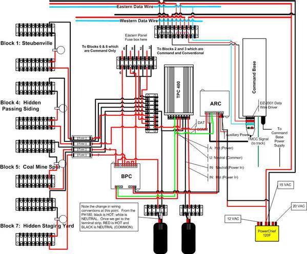
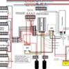
Track power is distributed from two panels (East and West).  A wiring plan for the western panel (Blocks 1, 4, 5, 7) is shown below.  The eastern panel is comprised of fuses, power indication lights, and terminal strips for Blocks 2, 3, 6, and 8.  Track power is provided by 2 Lionel 180 watt PowerHouse transformers. 


Switch machines and AC accessories are powered, respectively, by two K-Line PowerChief 120F transformers.  Switch machines (DZ-2500a, DZ-2500c) are controlled by push-buttons in the fascia or by CAB-1 via 2 DZ-2001 Data Wire Driver buses.  There are 21 switches.


Power for lighting, traffic signals, and other accessories comes from either a 12 VDC regulated transformer or a 3 VDC power supply.  Their is a 12 VDC accessory bus and a 3 VDC accessory bus.


All transformers sit on a converted TV stand next to the Western panel.


 20131231 Panel


Updates to the Layout

Updates to the layout (photos, notes, progress, etc.) will always be highlighted as new Comments.  Updates tend to appear as a running narrative or blog on the progress (or lack thereof) being made.  Your comments and “likes” are always welcome!


100,000 Views and Counting!


I thank you for your viewership. This edition marks the layout’s 5th appearance on the OGR Photo Album since 2004. Over the years, the Panhandle has been viewed more than 100,000 times.   


Please send me or post your thoughts, questions, and suggestions in the Comments section.


I hope you enjoy the layout and my journey through its construction.


George


Attachments

Images (8)
  • 1953
  • v226 PRR Panhandle Track Plan - Annotated
  • v226 PRR Panhandle - Hidden Storage Yard
  • Stubenville 2 Track 84 Inch (14)
  • DSCN0030
  • BLM2 002
  • NorthWeirton- with Lights
  • 20131231 Panel
Last edited by G3750
Original Post

Replies sorted oldest to newest

Updated 2/2/2009...

Several projects are underway on the Panhandle:
  • The Weirton Steel Open Hearth furnace is about 99% done. Need to replace some roofing material damaged in transit. After that it gets installed on the layout.
  • Need to finally glue down the track and roadbed supports on the PRR double track bridge.
  • Hidden Storage Yard: I am in the process of laying down track, roadbed, and wiring feeds for the under the layout storage yard. This yard is designed to hold around 50 cars (hoppers, ore cars, coil-covered gondolas) and will be entered from Weirton Steel. Once the yard is built, I will raise it up to join the lead spur and fasten it in place.


Lots of stuff to do!

George
Hi Dale,

Thanks for the compliment on the wiring. I'm trying to emulate Mike CT on the wiring front, plus there are some EEs at work who do outstanding wiring work. If I ever want to invite them to see the layout, I've got to keep up! ;^)

Not sure I understood your comment regarding mixing of transformers. And I was probably unclear in my previous comment.

The western panel holds the terminal strip pairs for districts 1, 4, 5, 7. The eastern panel holds the terminal strip pairs for districts 2, 3, 6, and 8.

Districts 1-4 which form the main loop and the passing siding (see Blue, Lt Green, Red, and Magenta track segments in Photo 2) are powered by two 180 watt Lionel PowerHouse transformers. These districts also have the TPC-400 in the circuit so that conventional locomotives can be operated there.

Districts 5-8 are yards and spurs and are powered by both sides of an MTH Z-4000. I tend to move the handles to 15 volts, which mates up with the command setting of "Low" for the TPC (been awhile since I played with these settings). Thus far, I haven't experienced any locomotives going into "rocket assist" mode as they cross from the Lionel / MTH boundary.

Hope that was clearer. Thanks for looking!

George
hi George

my concern is if a car or engine with dual pickup rollers bridges 2 power districts. This in effect would parallel 2 unlike transformers with a 22 gauge wire.

This wire can not take the amperage to drive a train and the sine waves of the Bricks and Z4000 are different and can not be properly phased. This could be an issue with the transformer outputs and would not be breaker protected.

If there is no danger of this then it would not be a problem. Maybe I am missing something in the track plan.

Dale H
George

They have a shared common whenever a train bridges the 2 districts. The outside wheels connect them if the trucks are metal. When the 2 pickup rollers from any dual roller car cross the block the 2 hot leads are connected. If this happens the 2 transformers are paralleled via the pickup roller wire and outside metal wheeled trucks. If the transformers are dissimilar like a Z4000 and a modern ZW,it is almost impossible to phase them correctly because they may put out different shaped sine waves. On like transformers IMO the commons should all be connected and the transformers in phase with each other. The bricks should all be in phase with each other as the plugs are polarized. Still if 2 adjacent bricks are paralleled at different potentials, the small wire in a dual rollered car is back feeding some current to the block with less potential. Some early bricks were out of phase with later model bricks. Again I would not use unlike transformers if there was any chance they can be paralleled via the rollers. I only see one loop on your layout and assume the power districts are all adjacent. This may be a problem.

Dale H
Thank you Trainman.

Yes, I decided to use Vinylbed a long time ago. If I were re-doing the layout, I might consider one of the embedded roadbed products. Of course, things were different back in 2002 when I starting buying materials. The switches are mostly Curtis - they're gone now. The surviving choices are more expensive.

Too bad about your move. Will it be tough to re-assemble your layout or is this the excuse to rebuild it (larger?)??

George
Dale, the situation is indeed complicated when connecting different power sources to adjacent blocks.

(First, let me clarify that "dual roller" cars are a problem ONLY IF the rollers are connected together internally. Many passenger cars have two rollers, but each roller is connected to its own isolated set of lights, with not interconnect between the two rollers. I recommend inserting a "Polyfuse" self-resetting fuse in series with one of the roller wires to provide protection in the event of a derailment that places one roller in contact with the center rail and the other roller in contact with the outer rail.)

The "added complication" is that the nature of the power controller needs to be factored in. Some of our controllers, like the Powermaster for example, will supply power, but will not sink power - somewhat like having a diode in series with the output that reverses its polarity on each half cycle of the AC waveform. Power from another device of a higher voltage connected across the output of the Powermaster cannot flow backward through the Powermaster.

The Powermaster uses two FETs in series, with one being the controlling device and the other acting as the diode. The roles of the two devices reverse on each half cycle.

The TPC uses a single device that is essentially a Triac. When a Triac is turned on, it can conduct current in either direction eually well. Although I haven't specifically tested this (disclaimer!!), this would seem to allow a TPC to sink current back to its transformer source if a higher-voltage source is connected to the TPC output.

I don't know what devices are used in the newer ZWs or MTH products.

If the controller device has a blocking "diode", then dissimilar waveforms don't create a big problem. The higher-voltage supply may temporarily try to power both blocks while any dual-roller units with internal interconnects bridge the blocks, but there won't be any power fed back into the other transformer.
I have used a Z-4000 and post war ZW's in adjacent power districts for 11 years connected with a common neutral. I have run over 50 differrent locomotives from 6 different manufacturers and countless lighted passenger cars and cabin cars from K-Line, Weaver, 3RD Rail, Lionel, MTH and Williams with never any electrical problems. I run in conventional control from th throttles.
Dale M

Thanks for explaining,I always learn something reading your posts. My one concern was the wire connecting the roller feeding the block and not being able to carry the amperage. Not too many people seem to be installing the poly fuses. BTW the specs on the polyfuses are for DC current but I guess AC is OK? As far as paralleling the different transformers perhaps no harm would come but it raises a concern with me. I think if the transformers were PW ZWs links of the secondary coil would burn. Even with the modern transformers, I do not think I would do it without seeing a schematic and knowing for sure.

Dale H
I have used the Polyfuses on AC for quite a few years. It would probably be wise to use the peak voltage of the AC waveform when selecting devices, rather than the RMS value.

"Old School" transformers with sliding taps certainly can cause a problem if two mismatched voltages are connected together. There is also the hazard of a massive stepup if one transformer is not plugged in. The power plug could easily have 300 volts on the power pins!
George

I think after reading Dale M's post (Dale M is a college professor and EE) you may be OK doing it. It raises questions with me that can not be definitively answered without examining schematics of both transformers. These may not be available to study because they are proprietary schematics.. It is also way beyond my pay grade as I am not an engineer.

At the very least on dual roller cars I would install the poly fuse to protect the wire,regardless of transformers if they are set at different potentials. If it were me I would be more comfortable with like transformers in phase. The MTH and Lionels could even be 180 degrees out of phase. Sorry I am not of much help, perhaps I should not have raised the issue. Maybe I am paranoid but I never parallel any transformers,but I do share commons.

Dale H
Well Dale H, I'm glad you raised the issue.

I will give this some thought. If there is a real danger of an electrical problem, then I need to do something. I don't believe in a fix-on-failure approach.

Right now, we are not running trains and all power is disconnected as I work on the hidden storage yard below the western end of the layout. It will be at least a month before power connections are re-established. The timing for a solution appears right.

Thanks for posting it. And my thanks to all who responded and contributed to the topic.

George
CFFisher:

There's a fellow at York in one of the halls (Silver?) that sells these in mint condition, but they are a bit expensive. I have only the painting part of the calendar.

I grew up looking at that fabulous bridge. It is really something to see in person. It is so massive, yet my father tells me about walking across it when a train was on it and it shaking!

Hey, that's an impressive layout and website!

Best,

George
Updated 3/1/2009

This last photo is one I took over a year ago. I was trying to see how many trains I could run simultaneously with one CAB-1 remote. The answer (on this small of a layout) is 4. We have a K4s ramming a stopped passenger train with multiple, minor injuries.

The subsequent NTSB investigation quickly dismissed reports of a large marauding orange Maine coon cat.

George
Last edited by G3750
Updated 3/13/2009...

Latest photo shows my hidden yard under construction. Ignore the date on the photo, I took the picture tonight. The yard will hold around 50 cars and will be accessible via a long descending spur. Construction details:
- Vinylbed (1/4" as per yards; 3/8" for mainline)
- Ross switches w/ DZ-2500 switch machines (TMCC controlled)
- Balloon reversing track with 4 stub end tracks inside
- Curves are all O31
- Track is mostly GarGraves, with some Ross sectional curves

George
Last edited by G3750
Updated 4/10/2009...

Photo No. 3 now shows the track plan for the hidden storage yard. This yard uses 5 Ross O31 LH switches. The turnouts are all TMCC controlled via Z-Stuff DZ-2500 switch motors. The yard sits on 1/4" Vinylbed. Being hidden, it will not be ballasted or sceniced. It has a reversing loop and 4 interior stub tracks. I think it will hold about 50 cars. Actually upon further review, I think 40 cars is probably closer to the maximum capaciy. If I'm really stacked up, I can put another 10-14 cars on the yard lead.

The purpose of the yard is to store trainloads of materials brought into Weirton Steel and to provide trainloads of steel products for shipping out of the mill.

As usual, comments and questions are welcome!

George
Last edited by G3750
Updated 5/17/2009...

Several changes are in progress on the PRR Panhandle:

1) The storage yard is well underway, with all 5 switches installed.

2) Reworking of the power distribution setup is underway. A Block Power Controller will be added to individually control power to Blocks 4 (Hidden Passing Siding), 5 (Coal Mine Spur), 6 (Weirton Junction), and 7 (Hidden Storage Yard).

3) I removed a Z-4000 power supply. The entire layout will now be powered by the two 180 watt PowerHouse bricks. The TPC400 will front them and various blocks will be controlled by the BPC as described in item 2 above.

I hope to have some updated photos soon.

George
Last edited by G3750
Updated 5/25/2009...

I have uploaded another progress photo from my work on the hidden storage yard. The 5 switches are in place. Track feeds are starting to hang down from underneath the subroadbed. The spurs are going to end up about 5-7" apart (center rail to center rail), but I think being able to get a hand in to adjust derailments might trump an extra spur.

As always your comments and questions are invited and welcomed.

George
Updated 5/26/2009...

Progress is temporarily halted as I have run out of GarGraves track to install. I have the length to finish one spur and enough pieces to finish a second, but will still need more. I'm also thinking about what additional track will be required to finish the Weirton Junction Yard.

Along with completing the spurs comes wiring the end-of-track occupancy detection circuits. I plan to signal the occupancy of each spur by turning on the light in rooms in various buildings around that end of the layout. Some very interesting vignettes are going to get illuminated... Wink Big Grin

George
Great stuff George. Glad to see it is coming together. I've been biking the Montour Trail (Railroad) since early May, made it to the McDonald viaduct Monday, which is also where the Panhandle Trail (Pennsy) ties into the system. This Saturday I hope to take the Panhandle Trail toward Weirton, WV. Maybe I can get some pictures. The McDonald viaduct is great.

Mike CT
Thanks Mike!

My next step after completing the yard and lifting it into place will be to tackle the power distribution changes to the total layout. I still have the BPC but haven't wired it into the system yet. In fact, I'm still working on the wiring diagram in spare moments. Gee, plan the work and then work the plan - what a concept! Anyway, I will get back to you just as soon as I have that done.

As to biking the trail, that sounds like fun. Maybe I will repost my thread "Ghost of the Panhandle".

Thanks again for commenting!

George
Updated 6/5/2009...

I finished laying the track for the hidden storage yard last night. There are end-of-track occupancy leads for every stub (all 4) as well as track bumpers. I've got automotive terminal strips under each stub for easy connection to lights somewhere on the layout. My thread in the Scenery Forum (dumpy hotel) is related.

I've uploaded a new photo (new #10) which shows the completed trackwork for this part of the layout (see Photos 7, 8, 9, 10 for stages of construction). I still need to wire the track (connect the feeder wires hanging down under the table). All track feeder wires will attach to a large terminal strip which will be wired to the western power distribution panel.

Next steps will be to wire and program the DZ-2500 switch machines, lift the yard to its correct height, and connect the yard lead track.

But we're getting there. Wink

George
Last edited by G3750
Updated 6/8/2009...

My hidden storage yard will use track occupancy circuits at the end of each stub track to tell the engineer when to stop backing the train. Each of those circuits will light a lamp in certain rooms around the layout. Most of those circuits will terminate in a dumpy hotel building just above the storage yard and next to the mainline.

In looking at the available real estate for the hotel, I came to the sudden realization that I would have to move a signal. The building will actually be a deep backdrop (6" deep at the building front and 4" deep at the rear of the building). To accomodate the hotel, the signal would have to move to the backyard of the building.

Yesterday, I moved the signal. This involved putting a new "floor" in place in the triangular space selected for the signal, relocating a terminal strip, and reattaching the wires. It was a tight fit, but I can see real potential for this dumpy hotel with the signal in back.

The only trouble is that my imagination far outpaces my available time.

George
Updated 6/30/2009...

My under the layout storage yard is built on a 3/4" plywood piece roughly 34" x 8'. It's temporarily propped up on plastic storage bins until I screw it into place.

Tonight I get a chance to do some real work. The family is out, it's just me and the cats (Pumpkin and Samantha). I've raised and propped one end of the board and now I'm working on the other. From a sitting position, I get the other end raised up and am about to put another storage bin under it when...the end of the plywood starts rocking violently.

I look up and there's Samantha walking up the lead towards the yard. I evicted her and managed to get the yard propped up without dropping it on my knees.

Curiosity...

George
Updated 7/15/2009...

Corrected and expanded the introduction to reflect changes in my thinking. Updated some of the descriptions of the existing buildings. All-in-all, minor editing.

I am hoping for some time off next week to get real work done on the layout. Areas of focus (in priority order) are:
  • Complete new electrical wiring diagram
  • Program all 5 DZ2500A switch machines for hidden storage yard
  • Raise hidden storage yard to its final position and mount in place
  • Reconnect power based upon diagram
  • Start running trains again


George
Last edited by G3750
Updated 8/7/2009...

Unfortunately, we suffered a refrigerator water-line leak in the early hours of this morning. The layout is not damaged, but work is halted while the water damage is assessed and restoration is in progress.

I was planning to bolt the hidden storage yard in place when this happened. Instead my oldest boy and I had to shoe-horn it out from under the layout so that a repairman could access the damaged ceiling tiles above.

What a mess! Frown Mad Eek

More when I know it.

George
Last edited by G3750
Updated 10/17/2009...

I had some inquiries from forum members while at York and figured I should update folks. We are not quite back in operation, but I can see the light at the end of the tunnel. All plastic storage bins have been transfered from under the layout to the furnace room. The train room carpet has been cleaned and most of the ceiling tiles are back in place. At some point in the near future, I will take the opportunity to inspect the bins, inventory the contents, and replace them back under the layout. Please see photos 4 & 5.

In January, I completed a scratchbuilt model of the Weirton Steel Open Hearth (greatly foreshortened of course). It's actually an oversized 3-dimensional backdrop. It's made of foamcore backing with Plastruct and Evergreen roof and sides. Two Lionel Industrial smokestacks add smoke to the room. That is in photo #6.

I also completed my hidden storage yard (photo 7) and was a few hours away from installing it when the water damage occurred. I still need to get it back in place, program the DZ-2500 switch machines, and wire it to the rest of the layout.

While all this was going on, Tommy Gilbert in Gettysburg completed the repainting and detailing of a Lionel Western Pacific Alco S-2 (TMCC, Railsounds) into Weirton Steel #208. The prototype joined Weirton Steel's roster new in December 1949. In photos 7 & 8, note the modified stack, safety striping and prototypical paint and details. Many thanks to forum member Price Bradshaw for storing the locomotive on his layout and allowing me to photograph it there.

More steel mill buildings, a highway overpass, some buildings and other things are in the planning stages, but first I need to get the layout powered and operational again.

Comments and questions are always welcome!

George
Last edited by G3750
Updated 11/20/2009...

With the help of forum member Mike CT, I was able to rework my wiring diagram. The layout will now use a Block Power Controller (BPC) to control blocks 5 (Coal Mine Spur), 6 (Weirton Junction Yard), 7 (Hidden Storage Yard), and 8 (Weirton Steel Yard). These blocks will be powered by a Lionel PowerHouse 180. The remaining blocks will be controlled by a TPC 400 (either conventional or command) which is fed by a second PowerHouse 180. The revised diagram is shown in Photo 4.

I am in the middle of changing the wiring right now.

George
Updated 11/28/2009:

ALIVE!! It's Alive!

Sorry, I got carried away with the Young Frankenstein references. Maybe it was looking at Teri Garr that caused it!

Anyway, I am pleased to announce that PRR Panhandle is powered and running and back in business!! I want to give a special thanks to forum member Mike CT for providing the BPC and proofing my wiring diagram.

The new Block Power Controller (BPC) is now part of the western power distribution panel and is controlling juice to Blocks 5 (Coal Mine Spur), 6 (Weirton Junction Yard), 7 (Hidden Storage Yard - when it gets installed), and 8 (Weirton Steel Yard).

The next step is refitting the Hidden Storage Yard back under the western end of the layout, programming its DZ-2500 switch machines, and wiring it to the rest of layout.

George
Last edited by G3750
Updated 12/21/2009:

I have more progress to report, although it is not strictly related to the layout. During the big snowstorm this past weekend, I was able to re-organize and catalog a number of storage bins holding train cars, automobiles, and related items. I now have an updated master list. Probably some thinning of the herd will take place soon. All these storage bins had been in the furnace room (workshop) since the water damage in August. These were moved to their usual storage spots under the benchwork.

Came home from work yesterday to find out that my eldest son had finished cleaning and organizing the workshop! Wow, what a nice surprise!

Then he helped me put the yard back under the layout. I still have to wire it up and program the switches, but we're making progress.

Bottom line, we're back in business. There are clean work benches and projects waiting!

Feels great!

George
Updated 02/14/2010:

Last night after a few hours of moving around support boxes and using a car jack, I finally got the storage yard into its (fingers crossed) permanent location. I still have to connect the lead track’s roadbed, but all other supports have been screwed into their locations. The yard is attached to 4 existing layout legs and I have one new leg supporting it as well. Wiring and programming of switch machines is next. The whole thing took about 5 hours. Photo 6 shows the yard prior to installation. The last 3 photos in the album show the yard as it is installed.

I'm pretty happy with how quickly it went into place. Progress!

As usual, your comments and questions are welcome!

George
Last edited by G3750
Updated 2/21/2010:

Tonight I completed wiring the hidden storage yard track to the western distribution panel. I also connected insulated control rails (used for detecting track occupancy) for the 4 stub yard endings to a master cut-off switch (single throw; quadruple poles). I updated the wiring spreadsheet for the western distribution panel. The yard uses cascading terminal strips; I just didn't want to have seven 6' wiring runs.

Given all the wiring, false starts, and reworked wiring over the past 4 years, I've nearly gone through the two 500' spools (red and black) of 14 gauge stranded wire.

Next up:
Lay the final connecting single piece of track to the yard
Program the DZ-2500A switch machines for the yard
Test, test, test!

George
Last edited by G3750
Updated 2/26/2010:

I seem to be swimming upstream against a heavy current. Talk about doing things the hard way... I should have installed the buss drops to the 5 yard switches (from above) BEFORE putting the yard in position. Makes it harder to run control wires.

The struggle here is to stay disciplined and wire ONE yard switch and then test it. The temptation is to do all 5 switches and end up backing that stuff out or debugging all 5 installs.

So far I've got buss drops to 3 of 5 switches, but my transformer cart has not been hooked up yet. Baby steps...

George
Updated 2/28/2010:

The struggle continues, but I am making some progress. Switches 17, 18, and 20 are programmed and operating under TMCC. Switches 19 and 21 still remain. I'm experiencing some problems with the pushbuttons, but we're still chasing those.

The layout has been powered up and the BPC is working properly. Track power to the yards is being controlled through that device. Power is available to the new yard (I have cabin cars lit up on all the stub tracks).

George
Updated 3/6/2010:

Wire nuts - both a blessing and a curse!

I've learned that wire nuts are really useful and potentially misleading when putting together two wires of different gauges. I had one disguising that fact that the two wires had become disconnected. That's what was causing my DZ-2502P pushbutton to show both RED and GREEN indicators as ON. I decided to check all the connections one more time, which is how I discovered the problem.

We probably don't have any issues with any of the DZ-2502Ps. I'm in the process of wiring those - maybe I'll get to them today.

George
Updated 3/07/2010:

I am still in the process of wiring the last two switches on my hidden storage yard, but I couldn't resist a test run of my Weirton Steel Alco S-2 switcher. I slowly ran it down the steep descent, O72 curve and long lead to the yard. I picked up a cut of 9 MTH ore cars and started back up the hill. About half-way, the switcher started to spin its wheels, so I cut off the last 4 cars. The locomotive inched up the descent like a champion and pulled the train completely out of the mill complex.

I will publish photos soon, but I had to post this. I'm really excited about this major piece of functionality.

George
Updated 3/14/2010:

As promised, I've added 3 new photos featuring the Open Hearth and the hidden storage yard. One of the photos (7, 8, or 9) has 2 things wrong. Can you spot it? If so, leave a comment.

I haven't had any time to focus on the problems with a couple of DZ-2500 switch machines, but they'll get my attention soon. I did clean up some of the wiring bundles. I also installed a ground plane per Bob Bartizek's instructions (OGR Run 218, December 2006). Thanks Bob!!

George
Thank you Charlie for the nice words.

That is the first structure I've ever scratch built (why did I pick one so big?). There are going to be more mills. To the left of the building will be an overpass (like you see in Photo 5) and then a blooming mill, office building, and then the Strip Steel mill. These should dominate the entire wall and corner on that side of the layout.

I can't wait to see your video. Is your H-10 conventional or command control?

My father (93) remembers triple-headed ore trains pulling into Weirton Steel in the 1930s. They were probably I-1s Decapods (that's my guess) or maybe M-1 Mountains. The timeframe is too early for J-1s.

I see by your signature that you are a member of PRRT&HS. I just mailed my application today.

Best,

George
quote:
Originally posted by pennsyk4:
George
My railroad is conventional control, using 2 control panels and block system
I added a sound board to the H-10
the PRR probably used hippos on that ore train your father remembers.


Charlie,

You're probably correct. William Neale, who's PRR Panhandle Division (in HO) appeared in a Model Railroader special edition, was kind enough to send me information on the bridge in Grif Teller's painting. I grew up in that area. Bill and I have exchanged info on various aspects of Weirton & Steubenville. Anyway, an April 2, 1927 edition of Railway Age magazine discusses the construction of the bridge (the 3rd on the site). The bridge was designed to bear the weight of multiple Decapod locomotives and a certain loading of axles per those locomotives and associated freight trains.

More than likely, it was I-1s Decapods that my father saw.

George
Update 4/14/2010:

I put in a ground plane just above the hidden storage yard, but apparently it is not big enough (only 1 wire). I will need to zig-zag more wire above the yard to maintain control. I had my first run-away train in the yard last night. I had to hit the E-Halt button; no damage, but a car was knocked off the track.

I've also been playing with track occupancy circuits using different ways to dim the lights. The bulbs are going to end up in a hotel (lighting different rooms) and they are not rated to handle 18 VAC track power. I may try wiring 2 in series to knock down the current.

Got the train room and layout cleaned up in preparation for some visitors prior to York next week.

I'm looking at some specially made pilots for the Williams K4s that may allow me to double-head them. I'll report back on how well this actually works.

That's it for now.

George
Last edited by G3750
Updated 5/1/2010...

I picked up some interesting things at York last week, including 18v LEDs, bases for them, and several sets of wired sockets for them. I decided to stop fiddling with diodes, resisters, potentiometers and the like and take the straightforward route. I have installed 5 of the LEDs for track occupancy circuits.

I also expanded the ground plane over the hidden storage yard by 3 wires which are attached to the main wire by "suitcase" connectors. That should help TMCC down there.

George
Updated 5/8/2010:

I attended the PRR Technical & Historical Society national convention in Camp Hill last weekend. I picked up some excellent information and materials on the Panhandle as well as some Tichy O Scale windows. It's time to start planning the next construction steps / projects. In no particular order:
1) Seedy hotel at wrong end of tracks
2) Finish Weirton Junction yard
3) Build more mill buildings
4) Build Weirton Junction tower
5) Build ingot mold cars for Weirton Steel

More when I know it.

George
Updated 5/9/2010:

I am pleased to report that NMRA judges visited the PRR Panhandle this past Wednesday and that I have earned my Electrical Achievement award.

To those of you who may have less than flattering opinions of the NMRA, I must report that I have been the recipient of much goodwill, sage advice, and respect and that my interactions with these folks have been nothing less than a blast.

George
Updated 5/11/2010:

We are now running Snappers (helpers for the non-Pennsy folks) on the PRR Panhandle!

Previously, I had used TMCC to double-head my K4 Pacifics. Tonight I put one K4 at the head of the train and one in pusher service at the rear and ran them as a single TMCC Train. It worked beautifully!

I realize to those running diesels, this is not a big deal, but I'm pretty excited about it!!!

George
Last edited by G3750
I'm pleased to announce that the PRR Panhandle Division has now been viewed more than 10,000 times in this go-around! In 4 previous postings over the past 5 years, it has been seen approximately an additional 28,000 times.

Thanks to all of you for your continued interest! Knowing that you are following the layout's progress keeps me moving forward.

Thanks everyone!

George
Last edited by G3750
Updated 07/08/2010:

I have been coming to grips (slowly) with the fact that I have waaaay too many freight cars for my layout. Years ago, I laid out plans for as many as 20 trains that might run on the PRR Panhandle. Unfortunately, I don't have the space to store them all and realistically, I can only run 3 (short) trains simultaneously. All of this got me to thinking about what the realistic length of trains could be. I am not only limited by the layout, but also by the pulling power of my locomotives. With the ability to double-head or use a snapper (pusher), I have become curious as to the practical length of my trains. So, here's my list of experiments that I'm going to run over the next month or so:

1. Number of K-Line & Williams 18" heavyweight cars that can be pulled by the M1a
2. Number of K-Line & Williams 18" heavyweight cars that can be pulled by the double-headed K4s
3. Number of MTH ore cars that can be pulled by the M1a
4. Number of MTH ore cars that can be pulled by the double-headed K4s
5. Number of MTH ore cars that can be pulled by the double-headed L1s+B6sb
6. Number of box cars that can be pulled by the M1a
7. Number of box cars that can be pulled by the double-headed K4s
8. Number of MTH ore cars that can be pulled by the 2 K4s in snapper configuration
9. Number of box cars that can be pulled by the 2 K4s in snapper configuration

All these experiments have to be done after properly lubricating the engines and freight cars (just to have a good reference point).

I will post the results here as we get them.

George
Updated 7/19/2010:

My first experiment (No. 1), the number of K-Line & Williams 18" heavyweight cars that can be pulled by the M1a, has been run. To be accurate, the train consisted of:

  • PRR B60b Baggage Car #9010 (Weaver)
  • PRR B60b Baggage Car #7906 - REA (Weaver)
  • PRR Broadway Ltd Coach #2544 (Williams)
  • PRR Broadway Ltd Coach #2543 (Williams)
  • PRR Broadway Ltd (K-Line set K4480-4486) Dining Car #4486
  • PRR K4480-6511 Railway Post Office #6511
  • PRR K4480-6042 Baggage Car #6042
  • PRR K4480-8815 Observation Car #8115 "Metropolitan View"
  • PRR K4480-0001 Pullman #0001
  • PRR K4480-3615 Coach #3615 "Herald Square"
  • PRR K3466 Coach #3466 "Times Square"


The M1a pulled 11 passenger / baggage cars with little effort. On my one difficult grade, the engine visibly slowed with all 11 cars, but I would estimate this to be nearly a 6% grade and on a curve to boot. It was pretty amazing to watch. And while I was moving the train by hand, I was surprised at how heavy it was.

I don't have any more "varnish" so this concludes Experiment #1.

More when I know it.

George
Updated 07/21/2010:

Just a couple of notes on the experiments...

One of the Weaver B60b's had a coupler that would occasionally open under the strain. Tonight I took that car out of the train and ran 10 passenger cars with the M1a just to see how fast I could go. I didn't have a speedometer, but I would guess we were doing much less than the 70 mph Pennsy limit for passenger trains (maybe 30 mph?). That 6% grade is pretty tough.

Also, I tried to run the passenger cars with double-headed K4s, but the second engine is having derailment issues. I'll have to look at that soon, but for the time being, that test is deferred.

George
Last edited by G3750
Updated 08/23/2010:

The doldrums of summer continue...haven't done too much on the Panhandle the past month what with summer vacation and kids' events. I did manage to:

  • Ship my second K4s off to a repair shop to fix the "wheelie" problem with the pilot truck. Should have it back soon and double-heading will be possible again.
  • Order and receive O scale styrene brick sheets (1900s Flemish Bond pattern) from the N Scale Architect for my Weirton Junction PRR interlocking tower.


I need to finish that time machine so I can get around to doing the 10 or so backlogged projects on my list! Big Grin

I'm looking forward to York.

George
Updated 10/1/2010:

Still haven't gotten around to fixing that time machine Big Grin, but here's the latest:
1) Got the second K4 back from repairs. Load testing to resume shortly.
2) Got the train room and office cleaned up (was waaaay out of control). Eek Passenger cars are now stored off layout (closet).
3) Watch for my new photos of my scratch-built ingot mold flatcars. I think that will be a new photo thread.
4) Revamped the To-Do list for the layout. Why don't these things get shorter?? Confused

George
Updated 10/9/2010:

Did some serious switching with the S-2 tonight. The switcher took 12 ore cars + cabin car down to the storage yard, moved a cut of 10 cars to stub track #3, moved remaining cars + torpedo car to stub track #2, and retrieved a cut of boxcars. With a running start, the S-2 and consist got back up the hill and tacked them onto another locomotive.

During the session, I tested Item 5 from my 7/08 list of experiments:
quote:
5. Number of MTH ore cars that can be pulled by the double-headed L1s+B6sb

The answer is "all I got" - 12 ore cars and I did not double head the L1 wth the B6sb. It did it by itself.

Also found two trouble spots with the track, which I will fix tomorrow.

George
Updated 10/11/2010:

With York only 3 days away, I finally completed my inventory and re-organization of the collection. I started this task two weeks ago and worked on it in an off-and-on manner. Several things have come out of it:

  • More efficient packing and consolidation of storage boxes holding the collection (each box is externally labeled and holds a content list within)
  • An organized spreadsheet of all boxes and their contents
  • An organized inventory of locomotives, rolling stock (by type), buildings, accessories, vehicles, etc.
  • A short list of items I want to sell or give away, many of which have appeared on the For Sale or Trade forum.
  • Improved organization of boxes and space under the layout.
  • Freed up storage space and shelves in the workshop.


Feels good to have this done.

George
Updated 11/1/2010:

I attended "The Great Scale Model Train Show" in Timonium, MD on Sunday. It really lived up to the name. I found a great number of Tichy windows and doors, wall-mounted lit bill-boards, roof ventilators, and other detail pieces you don't see very often. The windows solidified (in my mind) the design of the Weirton Strip Steel Mill.

This is good; we're going to end up with 3 mill buildings that have distinctive features but obviously share a pedigree.

Last night, I started a new project container with the windows and notes on the Strip Steel building.

Now all I have to do is live long enough to build all this!

George
Updated 11/3/2010:

As those of us building layouts know, we often revisit finished work and re-assess "done" items. Sometimes this is just a case of our own obsession for perfection, but sometimes there are real, lingering issues to correct. Right now I am debating some of the Panhandle's trackwork issues and the decisions that created them. Areas of concern are:

  • The metal bridge (7' in length) that spans the 2 segments of the layout. I expected a straight, rigid, perfectly bent "shelf" when I ordered it. That isn't what I got and I'm a bit frustrated trying to use shims to get it properly in place. I am experimenting with different braces to see if I can get a level platform with it. If I am unsuccessful, I will replace it with a 5/8" or 3/4" wooden deck. That will require lifting the double cross-over and re-wiring it. I've already taken photos of the underside wiring in anticipation of this dreaded task.

  • Several track joints are too wide and will need to be closed up. This will require re-location of power & ground track feeders, but I'm coming to realize the improvements will be worth the effort.

  • Several spots require more track screws to level out the trackwork and make for a smooth ride.

  • Several power & ground track feeds where I've tucked the wire into the rail will be replaced with spade connectors that snap into the track. This will improve electrical conductivity.


I've often said on this forum that reliability trumps all. It's time to make that a reality on this layout.

George
Last edited by G3750
Updated 11/8/2010:

Got a number of things done or underway this weekend:

  • Made track and roadbed repairs. Jury is still out on whether or not the metal shelf serving as a bridge will be replaced.
  • Repaired the roof of the Open Hearth (I had a section that had warped and bubbled).
  • Widened the south entrance of the Open Hearth to accommodate bottle cars.
  • Removed a non-functioning pushbutton (it has a partner that works). I tried to have 2 pushbuttons operate the same pair of cross-over switches. That doesn't work.
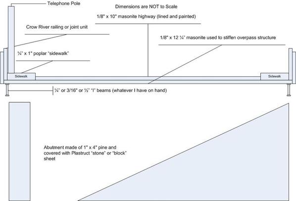
  • Cut the highway roadbed for the highway overpass at Crawford’s Crossing and determined its placement.
  • Came up with a way to mate two pieces of matte board for the roadbed in mid-slope (carpenter’s shims).
  • Determined the size and location of the Blooming Mill (billboard, transformer and stand); the detailed plan is now in progress.
  • Determined the location of both light towers in the Weirton Steel Yard.
  • Came up with a preliminary plan to separate Weirton Junction area from Crawford’s Crossing (small backdrop and tree line).
  • Came up with a preliminary design for the size and look of the Strip Steel. It will end up being the largest building on the layout.


George
Updated 11/18/2010:

Made some progress:

  • Painted all the Crow River components for the highway overpass.
  • Painted the highway roadbed (1/8" masonite) for the overpass at Crawford's Crossing.
  • Purchased automotive pin-striping (white) to use for the highway line markers.
  • Completed the plan for the Blooming Mill.
  • Partially built the frame for the Blooming Mill. This will be a foamcore building with a wooden supporting frame.
  • Located a photograph of the Strip Steel Mill that will serve as a reference for its construction.


Assembling the highway overpass will probably be the next task.

George
Updated 11/22/2010:

Replaced the photo (#6) of the Open Hearth with a better one showing my new ingot mold cars.

Did some work to determine the position of the Blooming Mill and the highway bridge (West Virginia Route 2 or Main Street) over Crawford's Crossing. Added a photo showing the approximate positions. In photo 7, the clamps are holding the legs in place while I level the building. BTW, the mill ended up being a bit shorter than is shown in the photo. I'm not sure the track segment protruding out of the Blooming Mill will survive - there isn't much space there. That's TBD.

The 4-lane road is a piece of 1/8" masonite which I will paint. I have its position finalized. Supports and guard rails (Crow River) for the overpass are painted; assembly is next.

As always, comments and questions are welcome!

George
Last edited by G3750
Updated 11/29/2010:

A Thanksgiving trip to Weirton yielded dozens of new photographs of the following areas / subjects of interest:

  • Strip Steel - got a number of shots of the building's end walls. I am working on the design for the layout.
  • Electrical towers - Weirton Steel used a variety of structural shapes and sizes of towers to suspend power lines.
  • Blooming Mill - while most of the mill has been torn down, some small pieces (the one I want to model) remains and I got some good shots of them. Should help sort out the proportion issue I'm struggling with.
  • Wall along Main Street - took some photos of the concrete wall for use in representing it.
  • Mill Administration Building - was able to capture some of the detailed brickwork in this structure.
  • General - got a number of photos showing the general deconstruction of the mill. Very sad, really.


Along with a great visit with family, this trip provided terrific resource material for new buildings and layout improvement.

George
Last edited by G3750
Updated 12/3/2010:

I had some progress since the last posting:

  • Made yet another height adjustment to the Blooming Mill, lowering it 1.25" (5 scale feet). This involved moving one of the side wall frames, but the change is more prototypical and helps keep the dimensions proportional. I tested the clearances and we are good to go.
  • Front and sides of the Blooming Mill have been cut out of foamcore using their new dimensions. They look much better. As soon as I get these photographed, I will mount them to the framework.
  • Ordered additional Crow River overpass pieces. I am considering repainting all of the components a sand color.
  • Figured out the height of the overpass. We are going to just clear any trains I run. Obviously, there can be no double-stacks on the PRR Panhandle!
  • Got the end wall design for the Strip Steel building worked out and on paper. This 3-D "backdrop" will be roughly 44" wide and 30" deep (at spots). It will have a ton of Tichy industrial windows.


That's it for now.

George
Updated 12/22/2010:

It's a good thing I had as much progress as I did leading up the previous post. The past 3 weeks have been consumed with family, car troubles, and work. However, some things did get done:

  • Made one more height adjustment to the Blooming Mill. What was that saying - "Measure once incorrectly, cut 3 times"?? Anyway, that's what I did. Finally, I have the correct height.
  • Also re-cut out the foamcore front of the Blooming Mill. Glued all the foamcore walls together and onto the frame.
  • Discovered the color of the prototype Strip Steel brick (yellow).


My immediate next steps are to get the foamcore roof on the Blooming Mill and order Tichy windows for the Strip Steel.

George
Updated 12/31/2010:

I removed some photos and added a new one. This last photo (#8) is of the Blooming Mill under construction. I've added foamcore walls, building front, and internal roof support to the wooden framework. The main roof and ventilator roof are ready to go as well, but doesn't appear in the photo.

You can see the prototype Blooming Mill in Photo 5 (left center) of this album.

George
Last edited by G3750
Updated 1/10/2011:

Couple of things to talk about:

  • To my great surprise, the PRR Panhandle photo album has been viewed over 15,000 times. If you add the 4 previous postings since 2005, you have over 43,000 hits. I thank you all for your patronage and support.
  • Progress on the Blooming Mill continues - siding has been added and the roof is in progress.
  • A friend surprised me with a large plotted poster (map from Rand McNally) of the Panhandle. I had it famed and it will hang in the train room.


More to come.

George
Last edited by G3750
Updated 1/14/2011:

Here's the latest:

  • I completed the roof, trim, and all major construction tasks on the Blooming Mill. For the first time, a second complete mill stood nearby my Open Hearth.
  • Last night we held the first Train Smoker, a name I made up to describe a gathering of friends and their children to view the layout and play with the trains. From all accounts, it was a great success. More will be posted on this event shortly.


In the very near future, I plan to add decals and some details to the Blooming Mill, order the windows needed to build the next structure (Strip Steel), and complete the highway overpass.

George
Last edited by G3750
Fantastic info, tho I M at the bottom of the heap control wise. I vote for phasing, believe its cheap insurance.

Good to see someone actually building out of fomecore and making good progress. Nicejob.

Thanks for the aside info on use of bus bars (building supply store) and/or the european style gang terminals (?) for junction wiring. I had several for some kind of use and was not able to decide what and how to use....

Oh yeah- R U doing something in the mill to simulate actual hot iron in ladle or ingots cooling? Could be quite imprissive!!!!!

again Thanks! Fine info and layout.

L
quote:
Originally posted by L Larson:
Fantastic info, tho I M at the bottom of the heap control wise. I vote for phasing, believe its cheap insurance.

Good to see someone actually building out of fomecore and making good progress. Nicejob.

Thanks for the aside info on use of bus bars (building supply store) and/or the european style gang terminals (?) for junction wiring. I had several for some kind of use and was not able to decide what and how to use....

Oh yeah- R U doing something in the mill to simulate actual hot iron in ladle or ingots cooling? Could be quite imprissive!!!!!

again Thanks! Fine info and layout.

L


Lars,

Thanks for the nice comments. Regarding activities or animation in the mills, I've certainly thought about something in the Open Hearth to simulate a pour. However, I've not hit upon anything that would be practical. For instance, I wanted to use a friction wheel to throw sparks coordinated with a sound module to simulate a pour. Trouble is, you don't really want sparks in an area with so many flammable materials around. So, I'm still thinking.

George
Updated 1/31/2011:

Recently, I have been struggling with the decision to re-do the front of my Blooming Mill. In trying to get the building ready for the Train Smoker, I rushed the application of siding and fudged a seam. I tried to correct it with paint, but it looks a bit shiny.

I took the building off the layout and looked at it again up close. From certain angles it looks OK, from others - not so much. I am going to try hiding the problem with weathering and see if that works. If it does, I will declare success. Otherwise...

That hasn't sopped me from ordering windows for the Strip Steel building or starting the detailed design.

George
Updated 2/4/2011:

No matter what the groundhog says, there will be at least 12 more weeks of model railroading this spring!

Accurately produced a full-size Microsoft Visio drawing (plan) for the front of the Weirton Strip Steel mill building onto three 11"x17" sheets of paper. The building front will be 44" wide with 7 bays and stand roughly 9" high (not counting ventilators and stacks). The building (really a 3-D backdrop) will be 5-sided and fit in a corner of the layout.

Haven't done the weathering yet on the Blooming Mill. Sometimes it's easier to work on the computer than the layout itself, but that's on the schedule for this weekend.

Talk at ya' soon.

George
Last edited by G3750
Updated 2/11/2011:

Baby steps. Sometimes it feels like I'm not moving forward at all. Misplaced the weathering powders and had to order a new set, so the Blooming Mill hasn't been touched.

Did cut a few pieces of craft wood for the framing of the Strip Steel Mill. Also bought some Evergreen styrene needed for that structure as well as Dullcote and Glosscote for decals.

George
Updated 2/16/2011:

Made a bit of progress:

  • I've got a outer frame built for the Strip Steel building. It's up on legs being leveled. I'm wrestling with some of the trackwork that encroachs on the space in front of the building. I need to keep a space between the climbing track and the front wall. Not sure if I will use a slope down to the building front or a retaining wall.
  • Starting to focus on completion of the highway overpass again. Gluing masonite to resin along a thin strip probably isn't a high percentage play. A friend has suggested the use of angle Plastruct pieces to cover the masonite and present a good surface for adherence to the Crow River resin guard walls. Definitely worth pursuing.
  • Put the weathered Blooming Mill back on the layout to check its appearance. Fortunately, the other buildings tend to mask the blemishes pretty well. Next step there is to apply the Weirton Steel decal, put it back on the layout, take a few photos, and declare victory!


That's it for now.

George
Updated 5/5/2011:

I've been preoccupied by other aspects of life (kids, health, York) over the past month and haven't done a lot on the Panhandle. However, the mind has percolating along. Here are the latest random musings to escape:

  • The way to finish the highway overpass at Crawford's Crossing is starting to take shape in my head. Thanks to a post on the Scenery Forum, I have a way to raise the piers to guarantee clearance. I bought the wood necessary to do this and will start this very shortly. Once the piers are supporting the overpass, I will work on the descending pier (an inclined plane of my own design). The final step will be to glue the side rails in place.

  • I've started gathering ideas, material, and information for the completion of the Blooming Mill's billboard. The billboard kit has been opened, I've printed a sign, and now I'm working on getting onto the backing and onto the building. Still need to drill the holes for the lights.

  • I've started searching my photo gallery of Weirton Steel for pictures of gas storage tank racks. The tanks are placed horizontally in rows on a girder framework. I'm not sure of their purpose, but on the layout they will serve to hide a track entering the side of the Open Hearth building. Plastruct has some parts that will work nicely. I'm roughing out the design and will shortly have the plans created in Visio.


That's it for now.

George
Updated 9/20/2011...

Non-train activities have been king around here for the past 6 months.

However, since the work is relatively mindless (no real planning required), I have been working on cleaning up the ingot molds that I had made. Finalizing them includes drilling, cutting, and sanding a hole in the top, painting the recessed slab orange, painint the rest of the ingot mold gray / rust, and weathering. Because I have 30+ molds to drill out, I am currently working on a jig to use in a drill press.

I also did an under the layout inspection and cycled the power. All TMCC functions working normally.

Hoping to find more time for the hobby soon.

George
The Steubenville- Weirton area is so depressed now. When I was a kid, I loved going to the A&P with my mom and I would wait outside and watch the PRR trains go through Steubenville. The Sears store was another great place to watch trains, but the best place was at my aunt's house on North 6th Street Rear. I would hear the train whistle and race down the back porch stairs and run to the wall next to the tracks. Those big K4s were beasts.

Larry
quote:
Originally posted by LLKJR:
The Steubenville- Weirton area is so depressed now. When I was a kid, I loved going to the A&P with my mom and I would wait outside and watch the PRR trains go through Steubenville. The Sears store was another great place to watch trains, but the best place was at my aunt's house on North 6th Street Rear. I would hear the train whistle and race down the back porch stairs and run to the wall next to the tracks. Those big K4s were beasts.

Larry


Wow, I am in awe. I was too young to experience Pennsy steam, but I remember that A & P and especially that Sears and its trains!!!

Thanks for bringing back memories.

George
George,

I was about 6 years old when steam last operated on the PRR mainline through Steubenville OH. Then it was diesels. I think the year was about 1957. The last steamer I saw was stopped at the Steubenville station and my dad went over the grade crossing on market street ( the gates were up). At the base of market street hill, I heard the bells of the crossing gates going down, the two short blasts of the whistle and the big K4 bellowed and started to move. The train was moving at a pretty good clip when the last car cleared the grade crossing. What a site!.

Larry
Larry,

Do you remember how Sears would have a big train display set up around Christmas? That Sears was the source of my first train set - a Marx All-State freight set (#666 2-4-2 steamer and tender plus 7 cars). Over the next 10 years I got more cars, track, and engines from that store - all as gifts. But walking in there as a kid was magical.

The General visited Steubenville in the 1960s. Did you see that?

George
Larry,

I had forgotten about The Hub. What a grand old store. Boy have you brought back memories. My grandfather and I used to the P & W bus across the river to Steubenville and walk around downtown. Stops were The Hub and S.S. Kresge (soda fountain & candy / nut counter). Later when I was of driving age (1970s), I would take him to Baker's Market on 6th for fish.

George
George,
A shopping trip to Steubenville was always an adventure when I was a kid. We'd park the car on 5th street by Krege's and start there. Move down to McRory's 5&10 then across the street to Richmond Brothers. Down the street to Penny's and lunch at the diner next to Pennys. Back to the Hub and after that to the car to go to Sears, Steubenville was really a bustling town in the day. My dad said that at one time Kaufmans and Gimbals in Pittsburgh were ready to build department stores in the downtown area, but the local businessmen on city council blocked them at every turn. Could you imagine what Steubenville would have been like if those two giants in Retail built stores in the late 40's early 50's.
Sadly Steubenville is a shadow of what it once was like most Ohio River towns, Weirton, Wheeling ... the list goes on. At one time Wheeling had 4 passenger stations B&O, PRR, W&LE and I can never remember the 4th station.
Larry,

By any chance, do you have a map or photo of the intersection of Market & 4th with businesses identified? Steubenville is part of my layout. About 5 years ago, I took a number of photos of present-day Steubenville. The variety of architectural styles and buildings still survive, although most buildings have been "modernized" (translation: made ugly). Obviously, the businesses that occupied them have changed. My layout's timeframe is 1948-1957 (that's a lot of leeway). Knowing the businesses that actually occupied the buildings would be helpful.

Given my space limitations, I can more-or-less model that intersection, but the rest of town will have to be "interpreted" loosely on the prototype. For example, I've moved the station off 4th (not 6th) and created a seedy area there. Model railroading is full of compromises.

If you do have such a thing or some thoughts, please contact me via my e-mail (in profile).

Thanks,

George
Updated 10/27/2011:

Well, I pretty much blew up the workshop this week. I just couldn't deal with it any more. I had gotten to the point where there were too many projects taking up the available work space. Some of the larger tools were also not well organized and the shelving was not flexible enough to reduce / eliminate the clutter. I finally reached gridlock.

So all the projects have gone on hold while I reorganize the shop. I'm not done yet, but I have managed to:
1) Dismantle a plastic shelving unit (5 fixed height shelves) and replace it with a flexible 6 shelf wire unit.
2) Consolidate the above shelf's contents with the project bins from under another workbench onto the new shelving unit. Big win!
3) Clear out and reorganize the crawl space (holds lumber now)
4) Sell off a bunch of excess shelving units
5) Transfer many train-related items to the large (and underutilized) closet in the train room. Reorganzied that closet to maximize its space utilization.

Still working on:
1) Assembling the workbench I bought last week to hold power tools.
2) Installing a new shop light over the bench
3) Installing pegboard in front of an existing workbench

Yes, the place is in a state of chaos, but lots of good things are happening.

George
Updated 11/3/2011:

OK, we are whittling away at the items on the list (and adding ones, too!). Latest changes:

1) The new workbench is assembled. As I was putting it together, I noticed there was now some wall space available next to it. So I took some of the scrap pegboard and put that up. It will hold drill bits and other items directly related to the power tools that will occupy the bench.
2) Installed a shop light over new work bench. I am about to put a power strip on the work bench - still figuring the best location for it.
3) As I neaten up the workshop, I discover items that can be organized. So I generated another bin of building and detail parts as well as one for figures.

We're getting there. Next steps are to get the power strip fixed in place and get the pegboard up in front of that existing work bench.

George
Updated 11/12/2011:

The power strips were installed on the new workbench. I also moved the drill press and hobby table saw to it. The mitre saw and other power tools are now stored below this workbench. This is a much better arrangement, freeing up space elsewhere in the work shop.

I finished the pegboard installation on another wall. The shop now has 3 new areas of pegboard; most of my tools and parts (screws, small electronic fittings, etc.) will be hung up and out of the way.

I am in the process of getting enough pegboard hooks, sorting out where things should go, and hanging them up. This feels pretty good - my shop is becoming usable again and I can't wait to finish some of the projects that have been hanging fire for weeks or months.

I will post some photos in the next few days.

George
Updated 1/3/2012:

Had a good friend over to run his recently acquired NYC Hudson (egad, "foreign" power on the Pennsy?) on the layout. It had some trouble negotiating a tight O54 downhill curve, so much so that it kept shorting out (pilot hitting outside rail). The situation brought into focus (once again) some of the uninformed trackwork decisions I made when I built the layout.

The good news is that he had a suggestion that may fix the problem once and for all. I am going to reduce the amount of grade on the curve and throughout the rest of downhill run.

I've also decided that the metal bridge deck across the Ohio River has got to go. It will be replaced with a hardwood rod structure (will simulate box beams) that will form the floor for the tracks and be securely anchored to the end points. In the future, I will be able to tie in a bridge superstructure.

I can no longer tolerate the poor track performance.

Last year around this time, I held my first Train Smoker - an open house for about 20 guests. Everyone ran trains, but I spent a lot of time holding my breath anxiously as the consists passed over the shaky trackwork. No more. Fixing the track is the pre-requesite to holding the 2nd annual Train Smoker. It's got to happen and I can no longer put it off.

George

Updated 2/18/2012:


Given all the other distractions in my life lately, my progress has been very slow.  However, I am pleased to say that I have just improved (reduced the amount of descent) in the grade coming eastbound off the PRR bridge at MP 42.11.  This has improved the tracking of all my locomotives in this area.  I intend to test this improvement with some visiting "foreign" power shortly.


George

Updated 2/26/2012:


Well, I carried out my tests on the "improved" descent east of the bridge at MP42.11.  Let's just say it's getting better, but still needs some work. 


Several days ago, I tested the track with doubled-headed PRR K4s.  The engines remained coupled and ran well over the areas in question.  I did not get a chance to run the Lionel M1a.   But so far, so good. 


Yesterday, I had a visit from my friend and forum member Price Bradshaw.  He brought along a 3rd Rail NYC Hudson with TMCC and a Weaver ATSF Hudson (conventional).  These engines were used to test the track improvements.


The 3rd Rail Hudson found the going a little rough, with the pilot hitting the rails at 3 spots on the track.  Those were marked for improvement.


The Weaver ATSF Hudson was more forgiving, cruising happily around the Panhandle like it belonged there.


I have since repaired one of the spots and am putting together my thoughts for repairing the others as well as replacing the bridge floor (which is a known trouble spot).


More when I know it.


George

Updated 4/2/2011:


This past weekend I made some slow progress rebuilding the mainline track work between the Weirton Steel Yard (WSX) and the eastern end of the PRR bridge.  In addition to the elevation changes (reduced the slope by raising the subroadbed), I replaced the electrical connections with Fastenol #60049 male disconnects (spade connectors).  I am about halfway done and am working backwards from the WSX yard to the bridge.  I anticipate some trickier track laying as I head toward the bridge.  Once at the bridge, I will pull up the metal bridge floor and replace it with the still to be designed wooden bridge floor.


George

Updated 4/10/2012:


Boy if there is a hard lesson I keep learning it's this:  Use 5/8" or thicker plywood for your subroadbed!


In rebuilding and re-laying the track, I keep finding and fixing low spots.  Having to reinforce them is labor intensive, but marginally less painful than replacing the subroadbed altogether.  My roadbed supports are spaced about 16-20" apart and that's just too wide.  So I am having to add additional bracing.


George

Updated 4/15/2012:


This low spot fixing thing has morphed into a full-blown adjustment of height, grade, track-joints, and electrical connectivity.   It seems to have taken on a life of its own.   


The large curve east of the bridge (not visible off the top edge of the figure below)  leading to Weirton Junction is the ultimate focus of the fix.  I've decreased the amount of grade there.  However, I've also discovered that raising the entire section of the track from the Weirton Junction to the Weirton Steel yard (that's the light green track) will improve tracking and eliminate derailments.  That's in progress.  All that track is being relaid, including slight placement adjustments of the roadbed and wiring connections.


George


v217Panhandle10x18-Repairs

Attachments

Images (1)
  • v217Panhandle10x18-Repairs

Updated 4/25/2012:


As I said in the previous post, the rebuilding thing has gotten out of hand. 


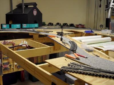
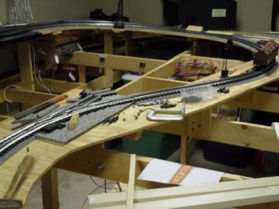
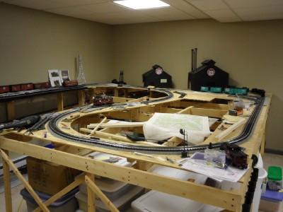
Here are a couple of progress shots.  In this photo, I am working on the track coming from the bridge (top-third left, just below the jade NYC boxcars) to the switch (Weirton Junction).  The open grid at the bottom left will become Standard Slag and a spur of Weirton Junction yard.  The idea is to design a removable segment so that I can reach the mills in the back if necessary.  That will be done much later, but I'm thinking about it now.  


Layout Reconstruction 005W2


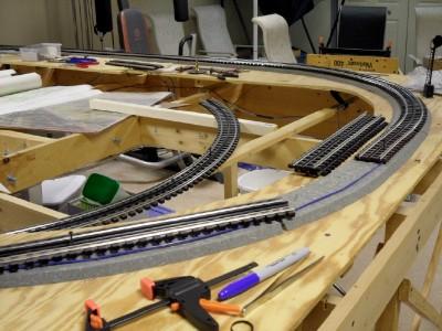
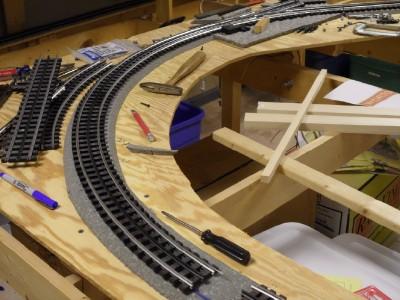
This photo shows the area just to the right of the above photo.  In it the completed track work heads to the Weirton Steel yard (top, background).  The blue wire is for super-elevating the curve.  The 2 curved sections are sitting atop the open framework in the center of the photo.  Curves are O54.


Layout Reconstruction 003W2


Comments welcomed!


George

Attachments

Images (2)
  • Layout Reconstruction 005W2: What will become Weirton Junction
  • Layout Reconstruction 003W2: Background - completed track to Weirton Steel

Updated 5/8/2012:


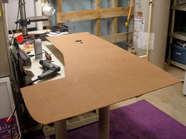
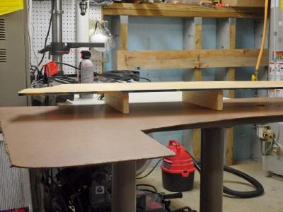
Construction of the "sandwich" (a bottom layer of 1/8" masonite, vertical ribs of 2 15/16" x 1" boards, and a top layer of 3/8" subroadbed) that will become the Standard Slag area is well under way.  The "sandwich" will actually be a removable access hatch.  This is an experiment - I'm curious as to how it will work.


I have decided that the Weirton Junction Yard will shrink to a single short spur and that a slag pit with a Lionel power shovel disguised as a Bucyrus Erie piece of equipment will be the centerpiece of the area.  Slag cars poised above the pit will dump hot waste down the steep slope, which will be built of carved foam.


Immediate priorities are the placement of the mainline switch leading into Weirton Junction, its adjoining switch (diverting to Weirton Junction spur) and the straight leg to Standard Slag (needs to be aligned with the edge of elevated pit). 


Fortunately, I have enough leftover Vinylbed to complete the project.  Once the roadbed is down, the track has been wired and placed, I'll start connecting up all the switch control wires to a modular plug of some sort (still TBD).


George

Updated 5/9/2012:


Managed to get two things done yesterday:


  1. Created a "portable" DZ-2500 programming station by velcroing a Command Base, DZ-2001 Data Wire Driver, and K-Line PowerChief 120F transformer to a board.  Also have a Euro-style terminal strip on the board.  A friend is about to start his track laying and I'm going to lend this to him.
  2. Programmed Switch #16.  This is located (but not shown) on the track plan in my 4/15 comment.  Switch #16 will be just under the label "Weirton Junction".

More when I know it.


George

Updated 5/10/2012:


Last night I managed to get just a few items done:

  1. I added another rib to the "sandwich" (at the eastern end).  There will probably be 1 more rib, I'm just now sure where it will go.
  2. I am planning to use a Scenic Express rusted steel wall as the way to hide the "parting" line between the layout and the removable "sandwich" or access hatch.
  3. Cut and added 1/8" masonite to fill in some of the areas that will support the wall.
  4. Placed a small block of wood under the bottom of the sandwich that will make for easy re-installation of the hatch.  The block keeps the sandwich in the correct position.

Logical next steps are installation of the Vinylbed switch pads, final placement of the track between the bridge and the switch, installation of electrical feeder wires in the track east of the switch and final installation of the #11 Switch itself.  After that we will lay Switch #16 and its spurs and complete the remainder of the mainline curve.


George

Updated 5/11/2012:


Made some more progress over the last day or so.  Switch #11 is now in place and mated to the mainline.  The mainline now extends from the bridge to Weirton Junction.  I am in search of 1" track screws to tighten down the entire length of track.


Next steps are to complete the sandwich area (bottom floor of the slag pit) and paint the entire area a slag gray / white color.


George

Updated 5/16/2012:


Decent progress has been made:

  • I made a good decision a couple of days ago.  Instead of trying to piece together scraps of masonite for the floor of the access hatch "sandwich", I bought a 4'x8' sheet and cut the piece to the proper dimensions.  A single piece was the correct solution;  I would have spent much more time playing around with a piece-meal approach. 
  • I installed "stops" (small blocks of wood) to help position the hatch on the layout.
  • I finally came to some decisions about how the hatch would be quickly removed.  After the electrical connections are decoupled, a scenic wall will be removed, allowing the hatch to slide out from the main part of the layout.  A number of clearances will be measured and marked for cutting.  Those spots needing clearance will be trimmed before anything else gets done.

Once the trimming has been done, the complete sandwich will be assembled.  This involves screwing the floor to the ribs.  Painting (a slag gray / white) will be next.  Following that, subroadbed, track, and electrical wiring will be installed.


George


Updated 5/22/2012:


Got a chance to work on the access hatch last night, finally attaching the bottom layer to the rest of the structure. 


In this photo, the structure is upside down on my workbench.  You can see the hole for the power wiring leads and the terminal strip to which they will attach.


MPLX 024W


In the second photo, you can see the wide or slag pit end of the access hatch.  "Blue" or "Pink" foam will be used as a filler to stabilize the "sandwich" and carve out the slopes of the pit.


MPLX 027W


Next steps include playing with the fit into the rest of the layout, applying a coat of paint, and installing Vinylbed, track, and wiring.  At some point soon, I will take a shot at carving the filler.


George

Attachments

Images (2)
  • MPLX 024W
  • MPLX 027W

Updated 5/28/2012:


A lot has happened over the past 5 days or so:

  • The access hatch has received its first set of foam.  I'm still feeling my way around that part of the project.  For the hatch, additional foam, carving, track placement and wiring, and final fitting remain.
  • Switches, track, and roadbed on the mainline have been realigned.  I think I have improved running performance on this segment - testing will prove that out.
  • Also on the mainline, electrical conductivity has been improved.

 This photo shows the track back in place from the bridge to Weirton Junction.

Weirton Jct Approach 001W


This photo shows the mainline curve west (railroad east) of Weirton Junction being placed and ready for installation.

Mainline Curve001W


The final photo shows the entire mainline back in place and powered up (note the lit N8 cabin car).  We are going to test run locomotives with scale pilots to see how we do.  Track screws and shims will be added where necessary.


Mainline Restored002W


George

Attachments

Images (3)
  • Weirton Jct Approach 001W
  • Mainline Curve001W
  • Mainline Restored002W

Updated 7/2/2012:


There has been some progress since I last reported here:

  • Foamboard has been laid down on the access hatch and roughly carved.  Joint compound will be applied next to smooth out the slopes.
  • I've acquired some slag from Scenic Express that will cover the slag yard in, well, slag.  That's prototypical.
  • I now have 12 resin sections of steel pilings that will act as the walls to hold up the slag yard.  I just painted them a Ruddy Brown shade with Krylon paint.  They look pretty good, if I say so myself.
  • A "plug" of foamboard has been created to fit into the north end of the access hatch (slag yard).  I got out the Foam Factory last night and carved it.  It will be faced with steel pilings.

The way I see things right now, when I need to remove the hatch, the plug will come out first, the electricals will be disconnected, and then the access hatch will pivot out and away from the layout.


George

Updated 7/29/2012:


Got a lot done lately in the past week or so. 

  • Started laying track on the access hatch (Standard Slag).
  • Ordered the Plastruct parts for the static compressed air tank at the end of the slag dump track used to tilt the slag cars.
  • Found components for the tanks and ordered Plastruct parts for the frame of this compressed air structure for Weirton Steel.

Tank Structure001W


  • Completed, except for decals and weathering the transformation of the 6-12751 Lionel Steam Shovel into the Bucyrus-Erie Power Shovel.

B-E Shovel01W

B-E Shovel02


That's it for now.  There are more details at the Standard Slag thread on the Scenery Forum.


George

Attachments

Images (3)
  • Tank Structure001W
  • B-E Shovel01W
  • B-E Shovel02

Updated 7/30/2012:


No progress since yesterday, but the following items are on the immediate "to-do" list:

  • Change the angle on the "plug" to give the slag yard a little more space.
  • Complete the roadbed placement, track laying, and wiring work on the access hatch.
  • Start bending the pilings to fit the dimensions of the access hatch.
  • Mount the steel pilings along the slopes of the slag pit.


George

Updated 8/13/2012:


Have made some serious progress on the Weirton Junction portion of the layout:

  • After an abortive attempt to apply decals to the power shovel, I came up with several fixes.  One area is getting a small "plate" (piece of Evergreen sheet) to make the Bucyrus Erie decal lay flat.  The other decal is being redone to eliminate white lettering on clear paper; we are using a prototypical older decal that puts red and black letters on a white base.  See below.

SS Logo v07W

  • Feeder wires have been run from the Eastern Power Distribution panel to the Standard Slag dump track and to the Caboose track.  These are shown at the top of the photo (4-position terminal block) below.


EasternPanel&WeirtonJunctionWiringW


Disconnecting the 4 feeder wires at the terminal strip and the 6-wire push-in connector for the switch machine allows me to pull the hatch out.


In the near future, I will apply the decal fixes and the decals, install the 6 wire connector for the DZ-2500A switch machine, and complete the scenery work that remains.


George

Attachments

Images (2)
  • SS Logo v07W
  • EasternPanel&WeirtonJunctionWiringW

Updated 1/1/2013:


My New Year's Resolutions with respect to the PRR Panhandle:

  1. Finish the Standard Slag access hatch area and install it on the layout
  2. Finish (about 65% done) bracing all remaining subroadbed to improve track performance.
  3. Replace the steel bridge floor with a wooden one, including rewiring of a double cross-over.

Hopefully, 2013 will not be as crazy as 2012 and I will get some modeling done.


George

Updated 1/25/2013:


I'm still doing my New Year's Resolutions, but some progress was made on an unscheduled item (Isn't that how it always happens? ):

  • Updated my already huge list of things to do.
  • Researched the conversion of old computer power supplies to general purpose DC voltage sources for my lighting.
  • Computed the lighting needs for each side of the layout.
  • Began laying out a plywood board to hold the powersupplies, fuses, and terminal strips.
  • Started re-organizing the transformer cart (former TV cart) to hold the new plywood board.  Expect to finish that shortly. 

More when I know it.


George 

Updated 2/20/2013:
Spent part of last night re-arranging the transformer (former TV) cart:

  • The plywood board with both computer power supplies mounted on it has been velcroed to the bottom shelf.
  • The bookend to hold up the manuals is now in place on the lower shelf.
  • The surge protector / power strip is now on top of the cart.
  • Both K-Line PowerChief 120F transformers are now on top of the cart in their designated locations.

The next things in this area's immediate To Do List are:

  • Fasten down all cords
  • Install a second power strip (daisy-chain it to the first).
  • Update the electrical wiring diagrams for the power supplies and put them into the manual.
  • Add each light / accessory / powered item to its respective power supply load chart and double check the load calculation.

George
Updated 3/10/2013:


Have made a number of planning and research types of improvements:

  • Updated the layout plan at the Building layer (way out of date) to:
    • Correctly position the Open Hearth Mill on the plan
    • Place the 5x5 oxygen tank structure just south of the Open Hearth
    • Pick new locations for the two floodlight towers in the Weirton Steel yard
    • Correctly place the Blooming Mill on the layout plan
    • Correctly size and place the Strip Steel building on the layout
    • Correctly size and place the Mill Administration Building on the layout.  Began researching this building's appearance circa 1957.
    • Correctly size and place the Quality Control Lab on the layout (new building).  Began searching for photos and sources of glassblock windows for this building.
  • Updated the layout plan at the Scenery layer to: 
    • Indicate a land form and scenic divider between Weirton Junction (north) and City of Weirton (south).  Two sided divider will separate these two scenes.
    • Correctly place the PRR Weirton Junction (WC) Interlocking tower on the layout.
  • Installed, but did not electrically connect, the two floodlight towers in the WSX yard.
  • Updated the electrical diagram for DC busses used in lighting or powering accessories (terminal strip => connector plug => terminal strip internal to accessory).

George

Updated 3/21/2013:


Have managed to get something done:

  • After a long struggle, I got the blade guard off my MicroLux table saw.  It's height was preventing me from cutting the resin castings of steel pilings needed for my Standard Slag area.  I still have several of those to be cut.
  • Installed a Lionel Accessory Motor Controller TMCC component on the Western power distribution panel.  It's wired but not programmed.  All related diagrams have been updated to reflect this.
  • Conceived and planned an Open Hearth animation of a steel pour.
  • Consulted with a friend who is an electrical engineer for the circuit design.  Circuit is based on a combination of those found in the OGR book Animations.  Currently researching and obtaining electrical components for the animation.

That's it for now.


George 

Updated 3/24/2013:


I've been making progress on the Standard Slag module.  Photo 1 show a set of steel pilings (center) that I have placed but not glued.  What's new is the foundation piece at the bottom of the stack that brings the pilings to the correct level.  This section also protrudes a bit from the wall to the right.  That wall will hold up a slipping embankment.


Std_Slag_W13_012


The second photo shows the steel pilings that will occupy the pink foam wall to the left in Photo 1.  This set of pilings has been glued to a piece of cardboard which will then be positioned and secured in place.


Std_Slag_W012_007


Photo 3 shows the inside of the Open Hearth mill.  Looking up you can see the smokestacks protruding through the roof.  The circuit board for the animation will probably set under the smokestack platform to the left.


Open_Hth12_010


George


Attachments

Images (3)
  • Std_Slag_W13_012
  • Std_Slag_W012_007
  • Open_Hth12_010
Last edited by G3750

Updated 3/30/2013:


  • Laid the final track for Standard Slag and trimmed it to the proper length.  There is now correct spacing for the compressed air tank and the end-of-track bumper.
  • Laid the final piece of track for Weirton Junction.  I still need an Atlas track bumper.
  • Got the backs of a number of steel pilings painted.  I used the same color as on the front - Krylon Ruddy Brown primer.
  • Heated 4 of them with a hot air gun and bent them to fit the curved edge of the Standard Slag module.
  • Trimmed one piling to bridge two different height plywood steps on the module.  Also filed down the joint compound at that spot.

I've decided to stop work on the module when all the steel pilings are in place.  I will leave ground cover and the build-up of adjoining terraforms to the very end.  This module will probably have to come out at least 1 more time to reach two areas (Crawford's Crossing Highway overpass and Strip Steel mill). 


The next mini-project to get some attention will be Crawford's Crossing Highway overpass.


George

Originally Posted by Buff:

Love all the pics and design.  Worked 17 years at WSX myself.  Keep going and good luck!

Thank you, Buff!  What part of the mill were you in?  And when?


Your kind comments and viewership are appreciated.  Since OGR changed the forum software a couple of years ago, the number of views is no longer displayed.  At one point, this photo thread (currently in its 5th incarnation) had been viewed more than 50,000 times.  Now, I can't tell if anyone looks at it unless they comment! 


Appreciate it and stay tuned!


George

Originally Posted by Buff:

I started in the Sinter Plant, spent a little time in the Blast Furnace, then the PowerHouse before moving up to the G.O.  Was there a while before going back down to the Slab Yard, Strip Steel, then finally up by #1 Gate.  I left on my own when they shut down the hot end.


You?

I was a summer (temp) employee in 1972, 1973, and 1974.  In 1972, I was a crane hook-up boy on the end of a plater in the Tin Mill.  In 1973, I worked in the Blooming Mill.  For a week, I worked the Hot Track, spent a Sunday in the grease pits, and then worked the rest of the summer as the shop boy in the Blooming Mill's Roll Shop (nice!).  The summer of 1974 was spent in the Strip Steel in various jobs.


After college, I worked at National Steel's R & D facility up on the hill from Fall 1976 to Summer 1978.  Then I went to graduate school for computer science. 


My father worked in the mill for a long time, ending in 1980.  He was an industrial engineer.  He's still active in the museum in town.


George

Updated 4/7/2013:


I am declaring victory (or at least a halt) on this module.  For now, I am postponing the super-detailing (minor ground changes, slag, ballasting, ground cover, etc.) in order to work on structures hemmed in by Standard Slag.


Here are some photos of the "finished" area.


This is the slag pit with the power shovel in the foreground and a dumping slag car at the top right.


DSCN0032


This show shows the steel pilings (before I put the green tank in place).


DSCN0026


This is the cabin car track at Weirton Junction Yard.


DSCN0027


This is a shot of the dump track at Standard Slag.  Two Lionel slag cars (with molten loads) are getting ready to dump their slag.  Note the green tank at the end of the spur - that is prototypical.  Weirton Steel used compressed air to assist in dumping their hot slag cars.


DSCN0028


Slightly closer look at the hot slag cars.

DSCN0029


This is a wider look at nearly the entire module.  The mills in the background are scratch built foam core structures with Plastruct & Evergreen sides and roofs.  On the left is the Blooming Mill; to the right is the Open Hearth.

DSCN0030


George

Attachments

Images (6)
  • DSCN0032
  • DSCN0026
  • DSCN0027
  • DSCN0028
  • DSCN0029
  • DSCN0030

Updated 4/8/2013:


I began planning the highway overpass and the area around Crawford's Crossing.  Photo 1 show the prototype in 1957.


1957_Crawfords_Crossing


Photo 2 is an old pic showing the components of the overpass between the Blooming Mill (left, under construction) and the Open Hearth (right).


2011-01-05_006W


The last shot is of the RR-Track plan of the area.  The overpass proceeds right to left.  After laying down the roadway components as shown in Photo 2, I measured distances from various fixed landmarks and compared them to the plan below.  I'm pleased to say they matched! 


Crawfords_Crossing01


The next steps will be to touch-up the railings and other Crow River overpass components with paint, add some height to the overpass abutments, and assemble.  I will also need to apply road markings (pin-stripes) to the next segment of Main Street and plan the elevation of the entire downtown area (it will be 1-2" about table top height).


George

Attachments

Images (3)
  • 1957_Crawfords_Crossing
  • 2011-01-05_006W
  • Crawfords_Crossing01

George,


I LOVE the pics!  Looks like you're coming along great.


I saw you have a couple of black slag ladles.  Later this week or next I was going to list three brand new black Lionel t-bottles that would match those perfect.  They're the plain black, Bethlehem Steel, ones with the flickering iron loads.  For another "Weirton" guy, I'll take care of you on them.


Drop me a line at 76erfan@comcast.net so we can discuss.  Don't want to take extra room on the forum.


Have a good one!


Paul

Updated 4/11/2013:


I have been giving some thought to making downtown Weirton a reality (see photo below).   This module was not the next step in my planned work on the layout, but I need someplace for the end of the overpass at Crawford's Crossing to attach.  So it makes sense to at least rough out the module and highway and attach the end of the overpass to it.  Still with me?  Good.


v218Panhandle10x18e


Currently, this is open grid bench work with risers, subroadbed and track. An irregularly shaped plywood table top supports the Weirton Steel mill area just to the right (out of the picture). Some reworked preliminary thoughts:

  • Just like the Standard Slag module (described awhile back in this thread with photos), we are going to make a sandwich.  The bottom layer of the sandwich will be a 1/8" masonite board that will extend south from the north edge of the Main Street to the edge of the subroadbed supporting the tracks to the south (unseen past the southern edge of the photo).  The masonite board will overlap the subroadbed, sitting on top of it.  It will be carefully cut to mate up with the boundaries of the track roadbed.  Eventually, ground cover will hide this seam.
  • The area south of the concrete wall will be almost 2" lower than Main Street. A 1:48 figure entering the front of the Quality Control Lab would exit the rear of the building at a lower level.  The concrete wall lining the south side of Main Street will have a total height of 4" (from the floor of the sandwich).
  • Our sandwich filling will be RIBS!   Unfortunately, they will be made of wood (1.75"x.75" pine) and will run North to South from the top edge of the module to the just north of the Concrete Wall.  They will elevate the Main Street.  I will space them at regular intervals to add rigidity to the module.
  • The top layer of our sandwich will be Main Street (masonite) and a separate section of masonite supporting buildings running along the north edge of Main Street.  That section will run all the way north to a vertical scenery divider that separates downtown Weirton (south side) from Weirton Junction (north side).
  • As you may have noticed, the bottom layer of masonite doesn't completely cover the entire module floor.  That's because we will need to reach the wiring (Lesson Learned from Standard Slag - you can't get your hand into a 2" high cavity to do wiring).  But a little of the bottom layer will extend north from the divider to give the Weirton Junction area a foundation.  That area will be populated with a small hill, a lot of trees (to blend in with the divider) and the WC (Weirton Junction) interlocking tower.

Hopefully that clarifies the diabolical plan.


Too bad about the ribs, isn't it? 


Talk to me folks, I'd like your thoughts.


George

Attachments

Images (1)
  • v218Panhandle10x18
Last edited by G3750

Updated June 12:


I have been thinking about how to start on the downtown Weirton module and that sparked a few more refinements:

  • I have decided to make the height difference between the top of Main Street and the bottom layer of the "sandwich" 2.5" (10 scale feet) at the Quality Control Lab.  This will give a complete basement story for that building (plus a step or two).  It will also have the benefit of making the slope up the overpass less steep.
  • Ribs for the module will start 2' in from the right edge of the drawing (where it says "Concrete Wall").  Proceeding right to left from that point, the rib heights will be: 3.0", 2.5", 2.5", 2.5", 2.0", 1.5", 1.0", 0.5".  This will permit Main Street to descend to track level at the extreme left side of the module. 
  • The bottom layer of masonite WILL cover the entire module floor.  I will cut large holes in it to allow wiring to be completed.  I changed my mind because strength of this module will be important, especially north of Weirton in the Weirton Junction portion.  The first step in designing this layer will be to trace out a template using butcher paper.

That's the current thinking.


George

Updated July 25:


I am working on multiple layout projects, sort of a small, medium, and large approach.  The small project is traffic signals (posted separately in the Scenery forum).  The Strip Steel Mill is my medium-sized one, and the City of Weirton module is the large project.  


StripSteel002W


Here are some updates for the Strip Steel.  That's the building in the photo above with the "Weirton Steel Co." sign on it.  The prototype has tracks entering it from the rear.  On my layout, I will model the front as it appears in the photo, but add a spur (already installed).


Last night I focused on planning the look of the building and its use of the spur track.  On my layout, the spur is straight up to the point where it curves into the building.  (The spur was built well before I knew exactly what building would be served by it). 

  • I taped together a paper mock-up of the front of the Strip Steel building (7 scale sheet drawings of each brick wall and its two bordering pilasters) and propped it up on the building framework (already in place).  From that I learned that the spur will enter the building at exactly the wrong spot - a pilaster.  This will look pretty bad.
  • My first alternative, widening the area between pilasters to accomodate the spur entrance, will also look goofy and ruin the symmetry of the building (see my photo above). 
  • So the only real choice was to alter the position of the spur.  I experimented with the placement of the curve using a spare piece of O42 GarGraves track.  Starting the curve 2" sooner will cause the track to curve nicely into the area between 2 pilasters.  I'll have to rip up some of the spur that's already in place, but the advantages far outweigh the disadvantages.

I'm really glad I did this with a paper template.  This is probably going to change what goes in some of these wall areas.  Jockeying a partially-built 43" wide building front to try to solve this would have been a major pain. 


George


Attachments

Images (2)
  • Annotated Strip Steel 002W
  • StripSteel002W

Here are photos of the mockup.  Photo 1 shows the entire front of the building.  The PRR mainline is in the foreground.


StripSteelFront_002


Photo 2 shows the close-up of the building and the spot where the track will enter the building (prior to correction).  The MTH Hot Metal Car #52 is on that track.  I will start the curve more to the right and cause it to enter the building in the second "bay".


StripSteelFront_001


George

Attachments

Images (2)
  • StripSteelFront_002
  • StripSteelFront_001

Updated 7/28/2013:


Last night I ripped up the mill end of the Strip Steel spur.  I poked around in my workshop and came up with some shorter cut GarGraves straights that will let me start the curve (into the building) a little sooner.  It looks like I won't have to even cut any track!  Because the table supporting the spur is wide, even the new track location should fit properly. 


I starting installing the new roadbed curve using the old Vinylbed.  I anticipate getting the spur re-installed tonight (as long as I don't get any interruptions).  If all goes according to plan (cue Murphy!), I'll try to post some new photos.


George

Hey there!  I live up on Marland Heights.  Small world, huh?  When you're ready, drop me a line here or at 76erfan@comcast.net .  I'd love to see what you're up to. 


Also, we have a small o-gauge club here in the valley.  No dues, no formalities, just a few great guys who get together once a month at each other's place to run trains and/or help each other out with building their layout.  Let me know if you're interested.  We'd love to have you.


Paul Buffington

Originally Posted by Buff:

Hey there!  I live up on Marland Heights.  Small world, huh?  When you're ready, drop me a line here or at 76erfan@comcast.net .  I'd love to see what you're up to. 


Also, we have a small o-gauge club here in the valley.  No dues, no formalities, just a few great guys who get together once a month at each other's place to run trains and/or help each other out with building their layout.  Let me know if you're interested.  We'd love to have you.


Paul Buffington

Paul, I very much appreciate the offer and will try to look you up when I get back in town. 

George

Updated 7/30/2013:


Right on cue, Murphy invoked his Law and I didn't get to spend very much time working on the Strip Steel spur.  However, in about 15 minutes I did manage to:

  • Assemble track pieces that result in a spur that fits within the available space.
  • Reposition the Vinylbed track roadbed and track and begin the process of fastening it down.
  • Verify that the end-of-track occupancy circuit (insulated rail) still works, run the wires, and find a spot for a terminal strip.
  • Work out a location for the light triggered by the above circuit.  It will illuminate a corner bay or hanging gooseneck lamp (over a man-door) at the extreme left side (as you look at it) of the building.

All I have left to do test fit the front of the building again and then screw down 2 pieces of track.  Hopefully tonight.


George

Updated 8/4/2013:


Since I last updated this thread, I have revised my thinking on several fronts and gained some insights into what I want to do with the Strip Steel building and the City of Weirton module:

  • First, the spur modification seems to be correct.  As currently laid, the spur will enter the building inside the 2nd "bay".  If anything, I may need another 1/4" somewhere, but that is easily "fudged".
  • Second, I have been looking at 1950s photographs of North Weirton to get ideas for sidewalks and telephone poles.  From those photos, I decided that the entire length of the overpass (Crawford's Crossing) had to have sidewalks.  I was planning to use 1.5" (6 scale feet) wide Crow River sidewalks.  For awhile, I thought that might screw up the spacing of the completed mill buildings and the Strip Steel.
  • Fortunately, I decided that the overpass could live with 1" (4 scale feet) wide sidewalks (2x) and managed to find an extra 2" in the spacing of Open Hearth.  I will be using the Ameritowne sidewalks for that.  I think we're going to be good there.

Next steps are to figure out how much of each sidewalk will be needed and order.  We will also need to engineer a support mechanism for the sidewalks and the road that will align the Crow River overpass sides properly.


George


Updated 8/5/2013:


I started a Survey of O Scale Sidewalks thread on the Scenery forum.  In the process, I began adding up costs for 33' (132 scale feet) of sidewalk.  Holy  !!!  If I executed the original plan, I'd be spending more than $200 just in sidewalks (and that doesn't cover the Steubenville, OH city area).  I will use my existing Crow River pieces on the North Weirton portion of the module and explore other home-made options for the rest.  Wooden yardsticks may be a reasonable choice.


George

Updated 9/19/2013:


There has been some activity on the layout, mostly in the form of research and acquiring pieces and parts:

  • Decided that I would use hardwood boards (1/4"x 1.75") for large number of sidewalks required in the city modules.  It's cost effective and should look good when scribed and painted.
  • Researched the look of North Weirton in the early-mid 1950s.  I now have an excellent set of photographs that show me the buildings, telephone poles, businesses, traffic lights, and street clutter that I want for the layout.
  • My trip to Weirton in late August yielded some photographs and measurements for the poured concrete wall that runs along Main Street.  I plan to build a section and make numerous castings from it.
  • Also during my Weirton trip, I got some photographs of the Strip Steel roof.  That will allow me to proceed in building it.
  • I placed orders for about half of the telephone pole components (transformers, LEDs) needed.  Also acquired a jig (courtesy of a friend's father) for bending 3/32" tubing into arms to hold street lights.  Still waiting on suppliers for the remaining pieces needed to build these.
  • Did some research on the appearance of downtown Steubenville, OH in the 1950s.  Got some photos from the library.  I did order a street lamp that looks pretty close to those in the photographs.  That, coupled with my 2001 era photographs of existing architecture, should give me some neat buildings to construct.  Right now that project is way down the priority list.

George

Updated 9/30/2013:


Over the past week or so, a number of telephone / utility pole components have arrived.  Transformers (Keil Line, Berkshire Valley, Crow River), hardware (Keil Line), and other detail parts (Crow River) have been delivered.  I am still waiting on a number of Weaver poles.


Plans for the types of utility poles have been finalized.  There are 7 different variations of poles planned for downtown Weirton alone. 


The immediate next steps involve a reset of the trainroom and workshop:

  • Updating my inventory spreadsheets with the detail parts received.
  • Organizing and placing all required parts into project bins (my usual way of keeping things straight).
  • Cleaning up the train room.
  • Straightening up the workshop (cleaning & tool replacement).

Things have gotten a little out of hand and I want to get some serious layout work going immediately after York.


George

Updated 11/17/2013:


Things have been a little slow while I recover from my arthroscopic knee surgery, but I did get a chance to work on a fun little project - my Crow River electromagnet. 

  • Used a pin vise to drill the 3 holes for hooks.
  • Installed the hooks.
  • Painted the electromagnet with Ruddy Brown primer.
  • Slathered it with a lot of Grimy Black weathering powder, followed by DullCote.
  • Glued a round magnet into the bottom cavity.
  • Installed some fine black chain using the hooks.

Will get a photo posted up soon.


George

Updated 12/1/2013:


I attempted to debug the operationg of the 5 switches on my hidden storage yard yesterday without luck.  Previously, I had identified some wires that were loose and had gotten 3 of them operating via pushbutton.  I had less success with TMCC remote control.  The next morning I tried again and none would work consistently.  After e-mail discussions with Dennis Zander, these DZ-2500A switch machines are on their way back to Z-Stuff for replacement with the "C" revision.


These were originally supplied as part of my purchase of Ross turnouts.  The "A" version switch machines on the rest of my layout operate properly.  I suspect these were part of a bad batch.  I know Dennis had some trouble with the "A" version.


Anyway, I have removed all 5, packed them up, and they are on the way.  Because of the way I wired them, removal was easy (about 5 minutes each).  The real PITA will be getting the spring back in place.


In the meantime, I am hoping for some warmer weather (50 degrees) so that I can get into the garage and paint the wooden bridge floor.


George

Updated 12/5/2013:


The weather did cooperate last night.  I think we got to 57 degrees, although it was misty / raining.  I managed to get the bridge floor painted, although I did not get to the track support members.  I will have to paint them another time.  The paint was applied with a small roller.  At first blush this morning, it looks OK.  Lighting in the garage was poor.  I will inspect the bridge floor more carefully this evening.


Also spray-painted a number of Crow River highway overpass components with a camo color (surprisingly decent simulation of concrete).  Most of these were touch-ups.  Didn't get to all of them and some will need touched up again (hard to see in the bad lighting).  I plan to do those tonight at a friend's spray booth.


The opening in the weather immediately slammed shut.  Temperatures falling today into the low 40's with rain.  Rain / snow mix expected overnight. 


More when it happens.


George

Updated 12/9/2013:


Today it felt like having your nose pressed up against the candy store window (look but don't touch).  Lots of stuff to work on, but domestic and parental duties interfered.  To wit:

  • My five new DZ-2500C switch machines arrived.  They need programming, but there was no time available to get the Command Base, DZ-2001 Data Wire Driver, and 15 VAC power supply set up.  I need to get these programmed, tested, and verified before I go through the grief of putting them back on the layout.

What I did get done was:

  • Cleaned up (removed flash and sanded) some additional Crow River overpass components.  They are ready for painting later this week at my friend's paint booth.
  • Researched and designed the "penthouse" structures on the roof of the Strip Steel mill building.  From the photographs I took in the fall, I was able to determine the correct proportions of the structures.  Now I have a good idea how to construct the roof properly.

Inching forward.


George

Updated 12/14/2013:


Yesterday, thanks to prompt service by Ross Custom Switches , my DZ-2001 Data Wire Driver arrived.  I used it, my spare Command Base, and a K-Line PowerChief 120F transformer to program my five new DZ-2500C switch machines (numbered 17-21).


Sw_Machine_Pgm_001_


Here's Switch No. 19 immediately after successful programming.  I will try to get these on the layout soon.


George

Attachments

Images (1)
  • Sw_Machine_Pgm_001_

Updated 12/22/2013:


I took advantage of the 65 degree weather today to get some painting done.  I opened the garage doors and made some progress.


The first 4 shots show my Crow River overpass parts that will make up the Crawford's Crossing highway overpass (bridge).  I used the Krylon Fusion #4291 Khaki color.  Makes a pretty good concrete color.

DSCN0030

DSCN0031

DSCN0032

DSCN0033


The next 2 photos show my bridge floor and track supports.  The supports, which are just on the bridge floor but not in their positions, were painted today.  I used 1.5 cans of Walmart Color Place black.


DSCN0034

DSCN0035

George

Attachments

Images (6)
  • DSCN0030
  • DSCN0031
  • DSCN0032
  • DSCN0033
  • DSCN0034
  • DSCN0035

Updated 12/27/2013:

Got back yesterday from a wonderful Christmas visit with my parents, sister, brother-in-law and their kids in Erie, PA.  We left Tuesday and got back yesterday.  Didn't do any model railroading during the trip, but did get some thinking and planning done regarding the highway overpass at Crawford's Crossing (see photo below).


1957_Crawfords_Crossing

That's not a great photo of the overpass, it is too far away and much of it is hidden by the pipe bridge next to it and the mill power line towers.  I'm planning to simulate the look with Crow River highway overpass components.   This photo shows the rough placement of the highway between the mill buildings.


2011-01-05_006W

What I had been struggling with was how to organize the structure  - add sidewalks, telephone poles, and the Crow River railings and joint components and have it all hang together.  Plus the highway must be 4 lane and the overpass must descend from a level height of 6" (between the mills) to the module floor into downtown North Weirton.  (NOTE:  The drawing doesn't show the upright bridge supports and wooden block necessary to achieve a 6" clearance.).  I solved that puzzle during the trip.


Overpass Drawing v002

A triangular support made out of 1"x 4" pine board will be used to ease the descent.  There will be one of these at each side of the road.  Disguised screws will be attached through the sidewalk into the support.  The roadbed will then be bent downward to mate with the module floor.  Screws will be inserted from the underside of the module floor into the supports to anchor them and achieve the downward slope.

I'm cutting a number of wooden components (sidewalks, underlying masonite) tonight.  Hopefully, I'll get to paint and scribe the sidewalks this weekend.

And the DZ-2001 buss work is still to be done.  That is also this weekend, assuming real life doesn't intervene! 


George

Attachments

Images (3)
  • 1957_Crawfords_Crossing
  • 2011-01-05_006W
  • Overpass Drawing v002

Updated 12/29/2013:


Well, the best laid plans of mice and men....sometimes get derailed.  Didn't get everything done like I wanted.  In fact, I've got a number of projects stalled for want of one thing or another.


Assembly of the Crawford's Crossing highway overpass is waiting on the sidewalks.  The 1" (4 scale feet) sidewalks did not get cut on Friday.  When they are cut, I will need to scribe their expansion joints and then wash them with an India ink / isopropyl alcohol wash.  In the meantime, I have been thinking about the location of those expansion joints.  Here's what I'm planning:


Sidewalk Drawings v01

Any thoughts on this?


George

Attachments

Images (1)
  • Sidewalk Drawings v01

Updated 1/6/2014:


Not a whole lot moving in this very cold weather, but some progress:

  • All sidewalks for the Crawford's Crossing highway overpass have been cut to their 1" (4 scale feet) width.  The sidewalks need to be painted, scored for expansion joints, and washed with the India Ink/isopropyl alcohol mix.
  • Underlying masonite "floor" for the overpass has been cut to the correct width to support the cross sections of 2 railing pieces, 2 sidewalks, and the roadway.  See diagram 2 posts up that illustrates this design.
  • Construction crane parts, specifically the boom and remaining cab and chassis, have been painted.  Still have to do all the smaller parts (wheel hubs, support arms and feet, etc.).

George
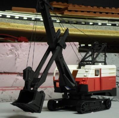
Last edited by G3750

Updated 1/12/2014:


Interesting week or so:

  • Was held up by the cold weather (unable to get out to paint).  A friend helped me with the use of his paint booth.  He also did a lot of painting for me.
  • Got all the sidewalks for Crawford's Crossing painted.  Scoring them will be saved for the upcoming weekend.
  • Got all the parts for the Lionel Construction Crane kit (6-19200) painted.  That kit was finally assembled and mated with my electromagnet.  Next steps are the application of decals, Dullcote, and some weight under the truck frame. 


Photos follow:


Crane_02_

DSCN0056

DSCN0057


Naturally, comments and questions are welcome!


George
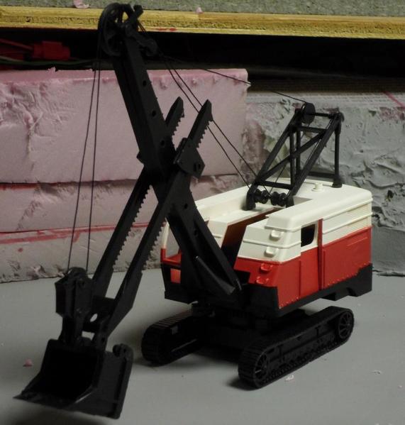
Attachments

Images (3)
  • Crane_02_
  • DSCN0056
  • DSCN0057
Last edited by G3750

Updated 1/13/2014:


Tonight I tested my jig for cutting a straight 6" line in a Weaver telephone pole.  I used my MicroLux table saw to make the cut.  The slot will hold a very thin wire and 3 VDC LED light.  The fact that this worked means that my plan for making lighted telephone poles is a "GO".


This is a big step forward for modeling lighted telephone poles.


George
Originally Posted by pennsyk4:

The latest PRRT&HS magazine, KEYSTONE, had a fine article on about the Panhandle Division

Hi Charlie,


You mean the one about Panhandle traffic?  Yeah, I saw it.  The author, Bill Neale, has one of the best Panhandle layouts (in HO) I have ever seen (only in magazines).  I met him at the last PRRT&HS annual meeting.  Very nice guy and very informative.


George
Updated 2/2/2014:


Happy Groundhog Day everyone!


While the excuse for a drinking party has been going on in Punxsutawney, I've been working on utility poles.   Over the past week or so, I've:

  • Investigated some touch-up paint for the poles
  • Assembled two of the more intricate variations of poles
  • Painted 6 of the 10 light pole arms

Excluding the final puttying of holes, sanding, and touch-up painting steps, we are 50% done.


Here are some photos:


DSCN0090

DSCN0091

DSCN0092

DSCN0093


Enjoy.  Comments and questions welcome!


George
 

Attachments

Images (4)
  • DSCN0090
  • DSCN0091
  • DSCN0092
  • DSCN0093
Originally Posted by pennsyk4:

Nice

I need to make about 6 for my Mifflintown.

When installed how many inches will the cross arm be above grade?

Charlie,


Thank you! 


I am using the 9" Weaver utility / line poles.  The have spaces (holes) for 4 cross-arms.  From tallest to shortest:

  • 8.75" (35 scale feet) above sidewalk or ground
  • 8.25" (33 scale feet) above ground
  • 7.75" (31 scale feet) above ground
  • 7.25" (29 scale feet) above ground

Note that Weaver also makes a 6" pole as well.  Check out the Weaver website for all the variations.


I can't say enough good things about these poles.  They are well made, look great, and are easy to work with.


Hope this helps.


George

Updated 2/17/2014:


I finally assembled a few lighted telephone poles and tested them.  Below are a few photos.


Telephone_PolesW_11_

Telephone_PolesW_12_

Power is supplied by 2 AA batteries (3 VDC).


Next steps involve:

  • construction of the remaining 7 lighted poles.
  • application of putty to all holes and slots on all poles
  • painting of all poles w/ touchup paint.
  • cutting my painted sidewalks to fit the Crawford's Crossing highway overpass
  • scribing expansion joints into the sidewalks
  • assembly of the overpass itself (2 sidewalks, 2 side rails, roadway, and support masonite)
  • drilling of holes for telephone poles
  • insertion of poles and attaching wiring to buss
  • cutting, painting, and assembly of large triangular ramp support
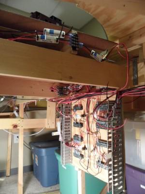
  • installation of Crow River overpass uprights

I hope to get to some of this over the weekend.

 

George

Attachments

Images (2)
  • Telephone_PolesW_11_
  • Telephone_PolesW_12_

Updated 2/26/2014:


I got the last 3 of this class of poles with double cross-arms, light arms, and two 3-wire stand-offs done last night.  Unfortunately, it was late and I didn't get a chance to photograph them.  Hopefully tonight, I will get the last 2 poles for the City of Weirton module done tonight.


Of those, the first is a 3 transformer job with standoff.  I find that drilling parallel holes in a pole to accomodate the transformer to be the hardest task.  Invariably, the holes are not completely lined up.


The second is a pole with criss-crossed insulator cross-arms (90 degrees to each other) and a light arm.  That shouldn't be too much trouble.


After that it's putty time.  All poles need to have their scars and extraneous cross-arm holes filled with squadron putty and then sanded and painted.  The telephone pole touch-up paint from Weaver arrived two days ago, so we're set.


George

Last edited by G3750

Updated 2/27/2014:


Didn't get a lot of time to work on the layout last night, but I did:

  • Manage to glue 3 transformers onto the one utility pole.  Aligning them was harder than I thought and they're not perfect.  But they will have to do.
  • Screwed up making a wiring groove in a pole for the final lighted one and had to remake it.  Looks a lot better.
  • Selected a piece of wood for the diagonal end of the overpass ramp.  This part is referred to as the abutment in the diagram below.  That will be cut tonight.
  • Collected all the upright supports that will be trimmed tonight.  These are 1"x1"x12" wooden blocks that sit under the Crow River bridge supports and add height.  They have been painted to look like concrete.
  • Confirmed the total height of the overpass.  The highway upright, with the additional support, will create a height of 5 7/8".  Subtracting the height of the Vinylbed (3/8") and track (0.45"), we're looking at a net clearance of slightly more than 5" from the top of the rail head to the ceiling of the overpass.  Good thing I'm not running double-stacks, vista-domes, or giraffe cars, eh?  
  • The height of the abutment will be 3.5" tapering to the module floor.

Overpass%20Drawing%20v002


George

Attachments

Images (1)
  • Overpass%20Drawing%20v002

Updated 3/23/2014:


I have finished assembling 28 of 28 utility poles for the North Weirton / Crawford's Crossing portion of the layout.  Now I am puttying the grooves in the lighted ones.  Will soon be painting.  Next steps are assembling the Crawford's Crossing highway overpass and installing the poles. 


In the meantime, I have started another (small ) project - a Weirton Steel caboose.  It is based on the PRR N5.  Awhile ago (2000-2001?) I bought a Weaver "Northeast" caboose lettered for PRR.  After becoming disenchanted with the Weaver crummy (lack of accuracy to the prototype), I decided to re-paint it.


The Weaver caboose looks close enough to an N5 to be made into the Weirton Steel caboose.  Unfortunately, disassembling it was difficult.  So I bought an unfinished, unassembled one from Weaver last month.  The new one has been painted and styrene panels have been added to hide the extra windows.  See below.


DSCN0045


It will be numbered "4" and will get the Weirton Steel logo just between the windows.


WSX logo


George

Attachments

Images (2)
  • DSCN0045
  • WSX logo

Updated 5/3/2014:


With the buzz of April's York meet and the PRRT&HS Annual Meeting winding down, it's time to take stock of Panhandle projects:

  • I managed to pick up another N6B cabin car at the York meet.

York_4_14_01_

  • Also saw the bridge built by East Coast Enterprises - we are discussing a few details, but I'm tempted.


Stubenville 2 Track 84 Inch [14)

  •  Found a vendor at the PRRT&HS meeting that sells PRR hairpin railing sets (for on top of the bridge)
  • Met another Panhandle modeler (in HO) at the PRRT&HS meeting and exchanged some interesting information and tips for the layout.
  • Picked up some more Tichy 20-pane industrial windows for my Strip Steel building.
  • Painted a few more telephone poles.  Need to finish that project.

That's the latest.


George


Attachments

Images (2)
  • Stubenville 2 Track 84 Inch (14)
  • York_4_14_01_

Add Reply

Post

OGR Publishing, Inc., 1310 Eastside Centre Ct, Suite 6, Mountain Home, AR 72653
800-980-OGRR (6477)
www.ogaugerr.com

×
×
×
×
Link copied to your clipboard.
×
×