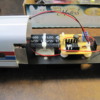
A while back I bought some reels of 12v LED strips on sale at MicroMark.  I decided to use these strips in my 5 Williams Amtrak metro passenger cars.  What I did was make a small circuit board for each car that contained bridge rectifier, capacitor, and 7812 regulator (and 22mh choke) and connected that to the LED strip.  That worked well, but a bit too well, as the cars were really bright.  And since I decided to use the bright white (5000K) LEDs for the modern passenger cars, it looked like someone had lit up a magnesium block in each of the cars.  Then I went back to the forum and reread several LED threads that suggested limiting the LED current to about 20ma.  I used my Fluke meter to measure the current that my setup was using and it was about 300ma (okay, so it was a bit high).


I then decided that the easiest way to retrofit my existing circuit boards to lower the amperage was to use the CL2N3 current limiter.  I had bought several of these about a year ago after reading a thread by gunrunnerjohn about LED lighting, but forgot that I had these until now.  So I took one of the CL2N3 devices an inserted it into the circuit.  It worked as advertised and limited the current to 20ma.  But since these cars have frosted silhouette windows rather than clear windows, I thought I could benefit from a little more amperage.  Since both GRJ and the Supertex data sheet say you can rack and stack these things to get more current, I decided to do just that.  But this is where things got weird.  The data sheet says you can put additional CL2N3 devices in parallel to get 40ma, 60ma, 80ma, etc.  I found that with two in parallel I got 35ma, with three I got 45ma, with four I got 55ma, and with five I got 60ma.  Not quite the linear progression that was described in the data sheet.


My question is:  Is this normal with these devices?  Has anyone tried stacking these things and measuring the current?  I seems odd that my results would deviate from the data sheet.  And I don't believe that I'm hooking them up wrong, since the connections are not rocket science.  Any ideas?


BTW, my question is just out of curiosity since I decided to go with adding 3 of these to each car for 45ma and they work fine.


Original Post

Replies sorted oldest to newest

I did put the CL2N3(s) between the 7812 and the LED strip and ran the transformer up to about 16v.  So there was 12v coming though the DC side.


I have a two wire keyed connector on the circuit board that goes to the LED strip.  I did this because these shells happen to slide on the frame rather than screw in from the top.  So I would slide the frame on halfway, then connect strip to the board, then slide it the rest of the way and screw it in.  This connector helped me test the CL2N3 before I did any clipping or soldering.  I ran a wire form the connector to a bread board then to the LED strip so I could try these out on the breadboard to see how many I wanted.


At first I thought that one of the CL2N3s was bad.  I then switched to my usual 12v DC power supply (8 D cells in a plastic battery holder) and hooked that up to the breadboard.  I tried that with several devices in parallel and that's where I got the readings above.  The data sheet suggested putting a 100nF (0.1 uF) cap across the power source.  I tried that and it changed nothing.


So the first CL2N3 does read 20ma at 12 volts.  Now does that first one affect the voltage differential enough such that the second one only does 15ma, etc.?  If that's the way they work, then my results sort of match what the chart says.


Lose the 7812 regulator, the CL2 is a regulator.  For a 12V strip, you'll need to get around 15 volts on the CL2 input to get a decent current out of it.  Just a rectifier, capacitor filter, and the CL2.  The filter needs to be a lot more than .1uf if you're feeding it from a rectifier, I recommend 330uf for flicker resistance.  You'll get proper operation that way.


John,


Thanks for the advice.  I didn't quite know how the CL2 worked and I just assumed that it would magically reduce the current while keeping the output voltage the same.  I can see that was wrong thinking.  I was so intent on measuring the output current that I never bothered to measure the output voltage from the CL2.  I think that by stacking these things with a 12v input, I started sliding myself down the ramp on your graph.


Since I got the results I wanted, it's easier to leave the circuit as is for this set of passenger cars.  But I will take your advice and lose the 7812 for the next set of cars I retrofit.  I run mostly TMCC so I will always have 18v on the track.


I tried the 0.1uF cap with my battery power only because they showed it in the example on the data sheet.  I had a feeling it wouldn't make any difference and I was right.


Now as far as the filter cap for the rectifier, I was looking beyond flicker resistance and into the realm of "lights stay on over gaps and switches".  Therefore, I decided to use a large cap (4700uF) because I had the room for it.  When I had the LED strip connected directly to the 7812 (300ma), the cap kept the lights on for almost a whole second.  Now with the CL2s installed (45ma), the cap keeps the lights on for 3 seconds after I shut track power off.  That's cool!  That's what I wanted.


I will attempt to post two pictures below, one of the original circuit, and one with the added CL2s.  I hope they come out.


amfleet-6

amfleet-9

Attachments

Images (2)
  • amfleet-6: Original circuit
  • amfleet-9: With three added CL2N3s

Under the category of Too Much Information, note that you're operating the CL2N3 on the sloping part of its operating curve.  That is, increasing voltage corresponds to a somewhat linear increase in current...in other words you're using the CL2 as a resistor (rather than a regulator).


I realize you already have the CL2s and you have a functional circuit.  But if the scenario was your built-up 7812 circuit (and no CL2s in your stash), you could simply insert a 68 ohm (or so) 1/2 Watt resistor in place of your CL2s.  68 ohms (or so) is the approximate slope in the datasheet graph and would give you a similar final operating current.  Resistors are ~5 cents.  CL2s are somewhat more spendy.


But I must say your assembly handi-work is top notch!

Originally Posted by Roger L.:

John,


Thanks for the advice.  I didn't quite know how the CL2 worked and I just assumed that it would magically reduce the current while keeping the output voltage the same.  I can see that was wrong thinking.  I was so intent on measuring the output current that I never bothered to measure the output voltage from the CL2.  I think that by stacking these things with a 12v input, I started sliding myself down the ramp on your graph.


Since I got the results I wanted, it's easier to leave the circuit as is for this set of passenger cars.  But I will take your advice and lose the 7812 for the next set of cars I retrofit.  I run mostly TMCC so I will always have 18v on the track.


I tried the 0.1uF cap with my battery power only because they showed it in the example on the data sheet.  I had a feeling it wouldn't make any difference and I was right.


Now as far as the filter cap for the rectifier, I was looking beyond flicker resistance and into the realm of "lights stay on over gaps and switches".  Therefore, I decided to use a large cap (4700uF) because I had the room for it.  When I had the LED strip connected directly to the 7812 (300ma), the cap kept the lights on for almost a whole second.  Now with the CL2s installed (45ma), the cap keeps the lights on for 3 seconds after I shut track power off.  That's cool!  That's what I wanted.


I will attempt to post two pictures below, one of the original circuit, and one with the added CL2s.  I hope they come out.


amfleet-6

amfleet-9


If you use a cap that big ,you may experience wheel arcing. Install and 18 ohm half watt in series to one of the leads if you have a problem.


I use a 7805 circuit and individual LEDs. I add 5, 1 Farad button capacitors, The lights stay on a couple minutes or more  gradually fading when power is removed.


Dale H

Stan, thanks for that extra bit of information.  I'll keep that in mind.  My knowledge of electronics is like a jigsaw puzzle with several pieces missing.  I do okay in the filled-in part, but really appreciate you guys helping me with the missing pieces.  I get myself into trouble sometimes when I start assuming what a missing piece looks like.


Just for fun, I have some pictures of the end result taken at the SD3R layout.  The first two were taken a few months ago with just the 7812 circuit at 300ma.  Note in the close-up you can make out a few of the silhouette figures, but sadly most were vaporized by the blast.  The third picture was taken yesterday after I installed the CL2s (at 45ma).  Note also that I taped over the holes in the frame so I wouldn't be lighting up the track below.


Some may argue that the lights are still too bright, but I kind of like it that way.  Besides, if I determine at some point that they are too bright, I can always just snip off a CL2 from each car.


layout-3a

layout-2a

layout-6a

Attachments

Images (3)
  • layout-3a
  • layout-2a
  • layout-6a
Originally Posted by Roger L.:

I didn't realize that 1 farad button caps were available.  Based on the size of the cap I'm using, I would think a 1 farad cap would be the size of an O-scale tank car.


And more trivia.


Your 4700uF, 50V capacitor can store about 1/2 the energy of a 1 Farad, 5V button cap.  For the same capacitance (microfarads, Farads, whatever) the energy stored is proportional to the voltage-squared.  So a 50V cap can store 100 times the energy of a 5V cap of the same capacitance.  It's true that technology in modern so-called "supercaps" gives them better energy density than traditional electrolytic capacitors like yours but these supercaps are typically low-voltage (5V).


But even a 1 Farad, 5V capacitor "only" stores about 10 Joules of energy.  Let's see. 10 Joules is equivalent to 0.000003 kW-hrs.  The average cost in the US for electricity is 12 cents per kilowatt-hour.  So a 1 Farad, 5V capacitor stores a whopping 0.0003 cents of electrical energy!  And your 4700uF/50V capacitor can store about 1/2 that.


Too much information.

Originally Posted by Roger L.:

Dale, thanks for the tip.  I'll keep my eye out for any arcing.


I didn't realize that 1 farad button caps were available.  Based on the size of the cap I'm using, I would think a 1 farad cap would be the size of an O-scale tank car.


They are about the diameter of a nickel and maybe as thick as 3 of them. They fit on the fish paper strips,which are glued to the roof. Here is the 7805 circuit but you could use a buck converter,set 5 volts or below.


LINK,78-05 circuit


Buck converter


LINK


The 1 farad capacitors do not need a resistor,they have some internal resistance.Remember to put them on the regulated side,they are 5.5 volts.


LINK2


LINK3


Dale H


Last edited by Dale H

FWIW, running them in series with the full 18 volts results in very bright lighting, far too bright for my tastes.  I typically run the 18" cars on around 20-25 milliamps for the entire strip. 


For strictly command use, a single diode, the filter capacitor, and the CL2 gets the job one nicely.  You can add a 22uh choke before the diode if you run DCS equipment.  The CL2 comes in 20 or 25 milliamp versions, so you can pick the 25ma version if you want things a bit brighter.  You can also parallel two CL2 chips to combine the current, two 20ma units will give you 40ma of current to the LED strip.


Originally Posted by Roger L.:

rtr12:  That's a flux capacitor which is a different animal.  You need that kind of power to get to the time travel part.


Was meant as a little humor and appreciation for Stan. I didn't know about the higher capacitor voltage storing more energy, great information. He has provided many of these little tips here (along with helping me several times). I try to follow them all, along with some other forum members that are always providing good information. If I could just remember all these things I would know something...


That was also one of my all time favorite lines, along with the flux capacitor being an all time favorite device.


Now back to regular voltage and capacitor programming...


Here's a good page that discusses Capacitors - Energy Stored.  As you can guess, it agrees with Stan's assertions, no surprise there.


Another point about capacitor energy is usable energy.  Let's say you have a load that requires at least 4 volts.  A 5V supercap will only provide a fraction of it's energy to the load before it falls below the threshold voltage necessary to supply the load, 80% of the charge is wasted and not accessable.  OTOH, a 35V capacitor, say charged to around 25 volts with track power, will be able to supply most of it's energy to the load before falling below the voltage threshold.  Figuring a regulator that requires a 5V headroom like the CL2, you can extract a majority of the energy from the capacitor before it falls below the voltage threshold.


Consider the following graph.  In the supercap example, you need at least 80% of the terminal charge voltage to supply the load, so you only get 1/4 of a time increment (whatever that is, dependent on the cap and the load).  OTOH, for the 25 volt charge, you get just about a full time constant before the voltage falls below the threshold for the load.  The net result is that you get to use a lot more of the energy stored in that capacitor that is charged to the higher voltage than the supercap that is only charged to a bit above the load requirements.


Last edited by gunrunnerjohn

rtr12: My "flux capacitor" response was meant to be humorous also, but I forgot to post the smiley face with it.    I too enjoy reading stan's posts.  He says that it is too much information, but it's never too much for me.


GRJ: For the single CL2 circuit, you would use a single diode rather than a bridge rectifier?


Originally Posted by gunrunnerjohn:

FWIW, running them in series with the full 18 volts results in very bright lighting, far too bright for my tastes.  I typically run the 18" cars on around 20-25 milliamps for the entire strip. 


For strictly command use, a single diode, the filter capacitor, and the CL2 gets the job one nicely.  You can add a 22uh choke before the diode if you run DCS equipment.  The CL2 comes in 20 or 25 milliamp versions, so you can pick the 25ma version if you want things a bit brighter.  You can also parallel two CL2 chips to combine the current, two 20ma units will give you 40ma of current to the LED strip.


John


If you look at the link they can be dimmed if desired with a fixed resistor. 1K works pretty well, but resistors up to 10K or even more can be used.  Lighting is subjective and at the discretion of the user. 


Dale H

Dale, the reason I go with a regulator is because as the track voltage varies, so does the light intensity.  If you have perfect power feeds, that's cool, but I've seen command layouts where the voltage varies several volts around the whole loop.  Sure, maybe that should be addressed, but meanwhile I have constant intensity lighting.


As far as light levels, you are certainly right, it does depend on the individual.  I go on my experience of having upgraded at least a couple hundred passenger cars for around 40 different people, most have preferred lower light levels than sunlight simulation from the lighting.  I've never had anyone that wasn't happy with the light output with my lighting module and the adjustment offered.  Since that tops out at 45ma, clearly most folks don't want the LEDs running at full intensity.  I tried a 12V regulator with the strips, IMO it looked ridiculous and way too bright! YMMV


Roger, you can certainly use a bridge, the single diodes is just marginally simpler and cheaper if you're wiring a bunch.  Also, the single diode will tend to give you a bit lower average voltage at the output of the filter cap.  Since the CL2 has a somewhat limited power dissipation, it's best not to have too large a voltage differential unless you want to supply a heatsink.  I've done a lot of cars that way, and it's worked just fine with nice steady regulated lighting.  You can use heat conductive epoxy to stick a small metal heatsink on them if they run too hot.  I have not had to do that with a single diode.  My lighting modules use a bridge rectifier and a TO220 LM317 regulator in constant current configuration.  It's adjustable from around 5ma to around 45ma.  With 18V AC input, the TO220 package runs around 70C with 45ma output, so I've never needed a heatsink on that one.

John, thanks for the explanation.  That makes sense.  I guess I was fixated on using bridge rectifiers.  Probably from reading too many Radio Shack electronics books.


BTW, I plan to always include the 22mh choke in my passenger car lighting circuits, even though I mainly run TMCC.  Since they are passenger cars, who knows what is going to be pulling them in the future.


Also, as a precaution, I plan to use the 22mh choke in any circuit that is directly connected to track power (such as accessory activation).  I believe that would be the same as putting a passenger car on the track, or probably worse because it's there all the time.


Add Reply

Post

OGR Publishing, Inc., 1310 Eastside Centre Ct, Suite 6, Mountain Home, AR 72653
800-980-OGRR (6477)
www.ogaugerr.com

×
×
×
×
Link copied to your clipboard.
×
×