I happened to be looking at a picture of a Canadian Pacific steam engine and would like to know how did they figure how much of a counter weight to add to the wheel when it was made. Thanks Paul
Original Post


|
|
I happened to be looking at a picture of a Canadian Pacific steam engine and would like to know how did they figure how much of a counter weight to add to the wheel when it was made. Thanks Paul
Replies sorted oldest to newest
paul 2 posted:I happened to be looking at a picture of a Canadian Pacific steam engine and would like to know how did they figure how much of a counter weight to add to the wheel when it was made. Thanks Paul
Long before the age of computers and calculators, the Mechanical Engineers used slide rules, and pencils & paper. Of course experimentation was also used. By weighing the crankpin, rod bearing, and the weight of the main & side rods, calculations were made to estimate the required counterweight. Also, those counterweights have a hollow area so lead shot can be added for final "trim weight", and then a steel cover plate is then welded over the hole on the back side of the counterweight.
Thanks for the answer Hot Water. Interesting information..........Paul

Big Jim, that picture of the cast wheel, was that the standard pattern for wheels or were there a number of wheel castings depending on the type of locomotive it was meant for.............Paul
paul 2 posted:Big Jim, that picture of the cast wheel, was that the standard pattern for wheels or were there a number of wheel castings depending on the type of locomotive it was meant for.............Paul
That is a much more "modern" wheel center. Note that there are no spokes, as was used in the earlier 20th Century.
Lead shot in the counterweights? Must be where that "choo-choo" sound comes from.![]()
![]()
Rusty
Attached pdf document has an engineer's explanation of balancing calculations for steam locomotive drivers, probably more than you want to know.
It was never possible to completely balance rotating and reciprocating forces for steam locomotive drivers, one of the shortcomings of conventional steam locomotives.
paul 2 posted:Big Jim, that picture of the cast wheel, was that the standard pattern for wheels or were there a number of wheel castings depending on the type of locomotive it was meant for.............Paul
There would be different castings for each driver position, as each wheel had less rods attached than the main driver. If you look closely at side views of 765, 611, 4449, 844, 2926, NYC Hudsons etc. you can see the different sized counterweights. HW's reference to a modern driver center, some engines when rebuilt in the later years of steam, got new driver centers such as Boxpok, and Scullin disc.
My problem has been finding small enough drivers, for O 3 rail, to build a steam coach, and other projects. I need small diameter drivers with spoked wheels and O width flanges. Any O 0-4-0 chasses have, in some cases, very large wheels and long wheelbases. Any diesel, etc. trucks have plain wheels. I widened an HO switcher chassis, longer axles, etc., using an AC-DC converter, but my flange widening was not successful. This to convert it into a powered front truck with steam cylinder, small spoked drivers and rods.
Marx's #999 early versions used spoked drivers...later versions used Boxpok. Would not modern computer technology make counterweighting steam loco drivers more of an exact science, IF anybody was still building steam?
While visiting the Valley Railroad Company in Essex, Connecticut this weekend, this post came to mind. Here's a side-shot of their Tangshan 2-8-2 steam engine showing some serious diversity:

Tomlinson Run Railroad

The counterweights put an equal and opposite force system into the drive wheels to counteract imbalances in the wheels and the effects of the drive rods. The hard part is determining the static and dynamic effects of the drive rods. These are called cross-head loads, and are variable.
All of the calculations by engineers at best are estimates, so there must have been some testing to fine tune the counterweights.
Bobby Ogage posted:The counterweights put an equal and opposite force system into the drive wheels to counteract imbalances in the wheels and the effects of the drive rods. The hard part is determining the static and dynamic effects of the drive rods. These are called cross-head loads, and are variable.
Please explain more.
All of the calculations by engineers at best are estimates, so there must have been some testing to fine tune the counterweights.
How would that testing have been done? None of the steam locomotive manufacturers had "in the floor test beds" like the PRR had in Altoona. Besides, how would that "testing" been accomplished back before 1900.
Hot Water posted:How would that testing have been done? None of the steam locomotive manufacturers had "in the floor test beds" like the PRR had in Altoona. Besides, how would that "testing" been accomplished back before 1900.
An excellent question.
Speeds were not as high in the early days of steam, so balancing wasn't as critical. Once driving wheels got to be 69+ inches balancing became more critical, but easier.
steam fan posted:Speeds were not as high in the early days of steam, so balancing wasn't as critical. Once driving wheels got to be 69+ inches balancing became more critical, but easier.
OK, what do you consider the "early days of steam" vs. high speeds? Locomotive/train speeds well above 80 MPH were not uncommon in the late 1800s thru the early 1900s. Also, passenger locomotives did indeed have drive wheels quite a bit larger than 69" diameter, way back then.
steam fan posted:Speeds were not as high in the early days of steam, so balancing wasn't as critical. Once driving wheels got to be 69+ inches balancing became more critical, but easier.
What, do you think those creaky, ancient "old-timey" trains from the 1870s couldn't get much above walking speed, and that with a tail wind?
Bah.
Trains from the Civil War onward were certainly capable of--and did--run quite fast--sometimes in the 70 mph range. And as HW pointed out, trains in the 1880s and 1890s went even faster. So even in the "early days," counterbalancing was critical.
Or by "early days," did you mean the 1830s, forgtting everything else until the 1920s?
Yeah, forgot about those hideous old 4-4-0's that could run 125 mph with 90 (sarcasm) inch drivers and 3 passenger cars. Speed is related to driver size, and larger drivers are easier to balance because there's more space to do it in. Look at the problems that N&W had with some K class 4-8-2's with 63 inch drivers...
steam fan posted:Yeah, forgot about those hideous old 4-4-0's that could run 125 mph with 90 (sarcasm) inch drivers and 3 passenger cars.
OK then, what about those very early (1900 thru 1920) 4-4-2s, 4-6-0s and 4-6-2s with larger than 69" diameter drive wheels?
Speed is related to driver size, and larger drivers are easier to balance because there's more space to do it in.
Please expound/clarify on that.
Look at the problems that N&W had with some K class 4-8-2's with 63 inch drivers...
steam fan posted:Yeah, forgot about those hideous old 4-4-0's that could run 125 mph with 90 (sarcasm) inch drivers and 3 passenger cars. Speed is related to driver size, and larger drivers are easier to balance because there's more space to do it in. Look at the problems that N&W had with some K class 4-8-2's with 63 inch drivers...
And then there's...


...with it's 97" driving wheel. You would think it could do better than 85mph.
Thanks for posting the detailed engineering protocols. They answered all my questions. ![]()
Hot Water posted:steam fan posted:Speed is related to driver size, and larger drivers are easier to balance because there's more space to do it in.
Please expound/clarify on that.
Pi x R2. Do the math. Larger wheel, more surface. Weights farther away from the center of rotation have more influence on dynamic balance. Crankpin 17 inches from center weighs more than counterweight 35 inches from center
steam fan posted:Hot Water posted:steam fan posted:Speed is related to driver size, and larger drivers are easier to balance because there's more space to do it in.
Please expound/clarify on that.
Pi x R2. Do the math. Larger wheel, more surface. Weights farther away from the center of rotation have more influence on dynamic balance. Crankpin 17 inches from center weighs more than counterweight 35 inches from center
In actual fact, the crankpin weighs the same no matter where it's placed.
Rusty Traque posted:And then there's...
...with it's 97" driving wheel. You would think it could do better than 85mph.
85mph was phenomenal speed for locomotives built 1870 - 1895, close to the speed records for that era. Large wheels helped keep the piston speeds in a workable range for sustained high speeds in regular service.
smd4 posted:steam fan posted:Hot Water posted:steam fan posted:Speed is related to driver size, and larger drivers are easier to balance because there's more space to do it in.
Please expound/clarify on that.
Pi x R2. Do the math. Larger wheel, more surface. Weights farther away from the center of rotation have more influence on dynamic balance. Crankpin 17 inches from center weighs more than counterweight 35 inches from center
In actual fact, the crankpin weighs the same no matter where it's placed.
True. 100 or 1000 pounds weigh the same no matter where they are. Put them on something round and rotate them though and it's a different ballgame. Take a bicycle wheel and put a 5 ounce weight halfway between the hub center and the rim. Now see how much weight it takes to counterbalance it 180 degrees opposite, and at the rim.
Here ya go old man, more math than you could use in 20 years. Is this expounded enough??? ![]()
 is:
is:

This force is provided by the pull of the connecting-rod and with reference to the following diagram:
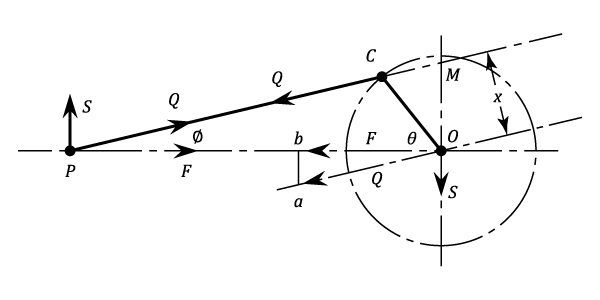
 applied by the rod to the crank pin
  is equivalent to an equal and parallel force through
  , together with a couple .
 ... tends to retard the rotation of the crankshaft and its effect is taken into account when finding the net turning moment on the crankshaft. is transmitted from the crankshaft through the main bearings and into the engine frame. and that at
  may be resolved parallel and perpendicular to the line of stroke. The horizontal components are equal and opposite. accelerates the reciprocating parts., is an unbalanced force applied to the frame and causes the frame to slide backwards and forwards on its mountings as the crank rotates.
 and
and  are similar:
 . Therefore,

 . So that
 and
and 

The full effect of the inertia of the reciprocating mass on the engine frame, is equivalent to a force  along the line of stroke at , and to the clockwise couple of magnitude
 .
.
 is called the Primary Force.
 which is called the Secondary Force
It is clear that the primary force is equivalent to the component along the line of stroke of the centrifugal force due to an equal mass rotating with the crank and at crank radius. Consequently, in the case of a single-cylinder engine, the primary reciprocating force could be balanced by a rotating mass on the other side of the crank pin. However, this would introduce an unbalanced component of the centrifugal force of magnitude  perpendicular to the line of stroke. A compromise solution (partial balance) is usually applied, the inertia force being reduced to a minimum when 50% of the reciprocating mass is balanced.
The secondary force is similarly equivalent to the component of the centrifugal force of mass at radius of  rotating at
  being coincident with the crank at inner dead-centre.
As a retired engineering manager, I can tell you that no company in their right mind would risk their reputation and survival by selling a high speed locomotive that would risk lives in the event of failure of drive wheels and drive mechanism failures. Additionally, no manufacturer would want the reputation of producing locomotives that pounded the customers tracks into excessive maintenance /early replacement.
Engineering calculations are estimates because they often contain assumptions / educated guesses for unknowns. This is especially true when starting a new design. Verification of analyses was typically done by testing of scale models / actual product.
In the case of a high speed locomotives drive wheels, a test might entail the spinning of a driver set on sprung axle supports. Knowing the support spring behavior, motions of the springs during the spin test can be translated into fine tuning the counterweights for actual inertial loads. Feedback from such testing enables the engineers to add correction factors to their analyses, so that future design calculations become more accurate.
Bobby Ogage posted:As a retired engineering manager, I can tell you that no company in their right mind would risk their reputation and survival by selling a high speed locomotive that would risk lives in the event of failure of drive wheels and drive mechanism failures. Additionally, no manufacturer would want the reputation of producing locomotives that pounded the customers tracks into excessive maintenance /early replacement.
May I suggest that you research the Baldwin built 4-8-4 locomotives delivered to the Atlantic Cost Line RR. The drive wheels were so out of balance, that the drives actually raised off the rail at high speeds, and damaged the track.
Engineering calculations are estimates because they often contain assumptions / educated guesses for unknowns. This is especially true when starting a new design. Verification of analyses was typically done by testing of scale models / actual product.
Again, may I suggest that to research how steam locomotives were designed/developed/improved, well prior to 1900.
In the case of a high speed locomotives drive wheels, a test might entail the spinning of a driver set on sprung axle supports. Knowing the support spring behavior, motions of the springs during the spin test can be translated into fine tuning the counterweights for actual inertial loads. Feedback from such testing enables the engineers to add correction factors to their analyses, so that future design calculations become more accurate.
How would/could such a "spinning test" be accomplished WITHOUT all the side rods mounted?
Bobby Ogage posted:As a retired engineering manager, I can tell you that no company in their right mind would risk their reputation and survival by selling a high speed locomotive that would risk lives in the event of failure of drive wheels and drive mechanism failures. Additionally, no manufacturer would want the reputation of producing locomotives that pounded the customers tracks into excessive maintenance /early replacement.
Hate to bring up a dead topic, but I was just perusing my library and came across a book titled, "The Steam Locomotive - Its Theory, Operation and Economics, Including Comparisons with Diesel-Electric Locomotives," by Ralph P. Johnson, ME, Chief Engineer of the Baldwin Locomotive Works (Copyright 1942, 1944). In it is an excellent chapter, including drawings, on Counterbalancing.
Nowhere in the chapter is made any mention of "testing" or "experimentation." Everything was done with calculations.
The chapter's Conclusion states, "The problem of counterbalance is still an open question. Every new locomotive cycle has been accompanied by re-occurrence of either damaged rails [due to dynamic augment. -SMD] or excessive locomotive maintenance, the causes for which were, in most cases, traced to deficient counterbalance methods."
There is definitely a corelation between driver diameter and max speed on the more modern steam locomotives much like the final drive gearing in an automobile. Other factors must be taken in to account, however, such as steam pressure, cylinder size as reciprocating speed much like an automobile. There is a legitimate comparison as the internal combustion engine derived from the steam engine. That old book sounds interesting. The boxpok driver has always intrigued me the way it is counter balanced.
Of interest in the discussion of cross-compound counterbalancing of engine drivers is the picture near the top of this thread, showing the bare driver center. This pictured center is actually for such a cross-compound balanced wheel. In this wheel, the added cross-balancing is added as a second smaller counterweight pocket located at 90 degrees to the larger main pocket. The small pockets lead the larger on one side of the engine, and trail on the other (just as the crankpins do... well, just opposite perhaps). Thus the casting for one end of the axle is exactly the same as that for the other.
These seem fairly rare, because it was quickly realized that the total added engine weight could be reduced by rotating the larger counterweight a few calculated degrees toward the smaller weight, thus eliminating the need for the smaller weight. This can be seen in pictures, and again, one pattern will serve for both wheels.
Yes, your engineering office would have calculated all this, and an effort to be as correct as possible would be made. But as certain forces (the reciprocating) cannot be counterbalanced in a mechanically simple design, a certain portion of the correction chosen is fudged by "engineering judgement." Hence an engineering office is often called a "fudge factory." Still, this process, however much ridiculed, contributed greatly to a last generation of steam power which was truly remarkable.
--Frank
The diesel may seem simpler than the steam engine...
But it is still a reciprocating engine, and while it turns somewhat faster than the machinery of a steam engine, it is not a lot faster; and it's transmission system of generator and truck-mounted motors is quite heavy. It seemed to replace steam overnight, but that was because it's thermal efficiency approached 40%, while even late steam power was pressed to get past 12%, resulting in a major saving in fuel costs.
The weight of the new engines ran close to a million pounds in 4 units, to achieve 6000 hp. The limit on horsepower in the heavy engines was imposed by the rotational limits of their crankshafts. Typically this was somewhere around 1000 rpm, because it was better in railway service to be below the lowest torsional vibrational mode of the crankshaft. A 4-cylinder engine plus flywheel on the back and harmonic damper on the front has six modes of vibration (corresponding to 6 frequencies to avoid).
Ideally, one has a computer to hand, because this solution has no simple formula, but must be solved by the convergence of successive numerical approximations to a correct answer. In the dawn of the computer age, this was not easy. No more numerous pages as for steam counterbalancing, but also no more certainty that the answer was a correct answer, as the number of cylinder grew ever larger. Eventually, the number of cylinders reached 20, and a lot of "decision-makers" became aware of the problem of torsional fracture in crankshafts the hard way.
It is fair to say that we are nearly three generations (customarily 33 years each) of engineers into the development of the diesel engines. The containment of 12,000 hp within 3 engines in place of 4 certainly took a generation, as did the steps from 1500 to 3000 hp per unit. More or less.
--Frank
And the old timers did it without the computer. There were some pretty long 12 cylinder airplane engines long before computers. The engines that fascinate me are the aircraft radial engines. Some of the multibank engines were pretty long.
F Maguire posted:The diesel may seem simpler than the steam engine...
But it is still a reciprocating engine, and while it turns somewhat faster than the machinery of a steam engine, it is not a lot faster; and it's transmission system of generator and truck-mounted motors is quite heavy.
Not quite. The weight of a boiler and firebox assembly was a fair bit heavier than a 16-cylinder diesel prime mover and the main generator system.
It seemed to replace steam overnight, but that was because it's thermal efficiency approached 40%, while even late steam power was pressed to get past 12%, resulting in a major saving in fuel costs.
The weight of the new engines ran close to a million pounds in 4 units, to achieve 6000 hp. The limit on horsepower in the heavy engines was imposed by the rotational limits of their crankshafts.
Really? How did you drive at THAT?
Typically this was somewhere around 1000 rpm, because it was better in railway service to be below the lowest torsional vibrational mode of the crankshaft.
Another generalized statement NOT based on facts. There were "critical vibrations" at various engine speeds well be low 1000 RPM. Besides, the first EMC/EMD diesel engines were only 800 RPM.
A 4-cylinder engine plus flywheel on the back and harmonic damper on the front has six modes of vibration (corresponding to 6 frequencies to avoid).
Which of course has NOTHING to do with any EMC/EMD 12-cylinder or 16-cylinder two stroke cycle diesel engines.
Ideally, one has a computer to hand, because this solution has no simple formula, but must be solved by the convergence of successive numerical approximations to a correct answer. In the dawn of the computer age, this was not easy. No more numerous pages as for steam counterbalancing, but also no more certainty that the answer was a correct answer, as the number of cylinder grew ever larger. Eventually, the number of cylinders reached 20, and a lot of "decision-makers" became aware of the problem of torsional fracture in crankshafts the hard way.
REALLY??????
It is fair to say that we are nearly three generations (customarily 33 years each) of engineers into the development of the diesel engines. The containment of 12,000 hp within 3 engines in place of 4 certainly took a generation, as did the steps from 1500 to 3000 hp per unit. More or less.
--Frank
The 765's drivers were tuned up at TVRM in 2004 or so during its last full running gear overhaul. New Tires were applied, cracked spokes were welded, several crank pins replaced and the drivers were quartered. FWRHS's late project manager Glenn Brendel worked with TVRM to weigh each set of drivers from side to side (no, I don't know how you actually do that) but Glenn reported that the weights on one side of a driver set were so close to the other side that there was no reason to tinker with adding or removing lead from the counterbalances. I think the weights on a single driver set from the left side to the right side were within 5% or less. The last time they were touched by the NKP would have been its last Class Repairs at Conneaut, Ohio, in 1955. The 765 operated about 65,000 miles before being retired plus another 50,000 miles in her Second Career or 115,000 miles total. Anybody who stood within one hundred feet of the 765's running gear during the TRAINFESTIVAL 2009 runby at Ithaca, MI and paid attention to the sound was amazed how little noise the machinery made. When it was backing up it seemed to be almost silent with no rod clank, etc.
Access to this requires an OGR Forum Supporting Membership
