
I've been trying to use 1008 relays on a ross double slip switch to prevent engines from stalling out on the switch. So far this hasn't worked. I've wired the relays as per the instructions on the Ross diagram. I'm using DZ 1000 switch machines.


However, every time a wheel set passes over the short rails powered by the relay, I get a short.


Several questions:

1) How do I know if the relays are working properly? How do I test them?

2) Any clues as to why I'm getting the short? 


Your help would be greatly appreciated!


Tom

Original Post

Replies sorted oldest to newest

I had the same issue with a recent installation of two Ross double slips.  I had to reverse the grey and white wires on both relays from what is described in the the instructions.  Top relay white to rail #2, grey to rail #1.  Bottom relay white to   #3 and grey to #4.  Also, be sure the DZ switch machines are mounted as shown on the Ross instructions.

Unfortunately I'm still having problems. I did discover that I had not installed the switch machines according to instructions. (The top switch in the diagram is my bottom switch, and vice versa. Unfortunately I cut ties to accommodate the slip switch, so I can't undo this error.)


I have tried all combinations of white/grey wire attachments but am still getting a short. My bottom switch (top switch in diagram) is currently wired relay white to rail 2, relay grey to rail 1. My top switch is wired relay white to rail 3, relay grey to rail 4.


My test car proceeds through the switch on the right whether it is thrown straight or curved. But it will only go through the switch on the left in one direction. If I throw this switch, I get a short. If I reverse the wires, the short occurs on the other leg of the switch.


Suggestions?


A few other questions.


Should the blue wire be soldered to the center rail of the switch to supply track power? The Ross diagram doesn't specify where it should be attached.


How do I test whether these relays are working properly. I have tried testing connectivity, but the results make no sense to me. I have also heard clicking sounds from one of the relays -- does this indicate that it's bad?


Any light you could shed on these problems would be most helpful.


Tom


Tom: #8 double crossovers are a bugger. . We are wiring the lead rails powered on the common side instead of hot.  Depending on which wire gray or white you have on thee straight lead rail that wire should be attached to the normally open lead from the relay. The position of the turnout motors if you are using Zstuff motors is critical as it the position of the LEDs in the switch motors. If I can find the drawing we use I'll email it to you Tom do not see your email, mine is in my profile. If you send me a email I'll attach drawing  in a reply.

1. The blue relay wires can be connected to any track power hot source.  It does not necessarily have to be a center rail on the switch.


2.  It is important to remember that the power to the switch machines/relays must always be on before rolling stock passes through the powered slip switch or the wrong embedded rails can be getting track current through the relay's normally closed contacts and cause the type of short you describe.  (That clicking sound you hear is likely a relay coil switching blue wire current to the normally open contacts where is is supposed to be going based on the way the DZ1000 has the turnout directed.  Blue to grey is through the normally closed contacts and blue to white is through the N/O contacts.)


3. The continuity item to check on a relay that is off line is from the blue lead to the grey.  This is through the relay's normally closed contacts.  If you don't get continuity there, the relay is bad.


2. With the machines located as you described, the points on the right side are being controlled by the lower DZ1000, so that relay should be connected to rails #1 and #2.  The top relay handles the #3 & #4 rails.

Start with the bottom relay.  Turn on power to the switch machines and set them so a piece of rolling stock would pass from lower right straight through and out the upper left. Turn on track power so the blue wire is hot. With your volt meter see if the white or the grey wire is hot by connecting one meter lead to ground (outside rail) and the other end to each of the two relay leads in turn.  Connect the hot one to rail #1. The other goes to rail #2.  Then do the same thing for the top relay.  Connect the hot lead (white or grey) to rail #4 and the other one to #3.  Now, if the relays are good, no matter which way the switch points are directed the proper embedded rails should be powered at the proper time.


As a matter of fact, before connecting any white or grey wires, use the voltmeter as described above to see if the white lead alternates between hot or not as you throw the switch points back and forth with the push buttons or whatever you have.  If it doesn't, the relay is bad.


Good luck. 

Bucky,

Many thanks for your lucid instructions and testing procedures. It definitely appears that one of these relays is bad. (Call this relay 1). Power goes only to the grey lead. The other relay operates intermittently. It operates correctly until I change the switch points involving relay 1. Then relay 2 gets stuck on one position or the other.


Thoughts about this? Is relay 2 bad as well, or is there an interaction between relays 1 and 2? 


Tom

Tom,


With everything wired properly there should be no interaction between the relays.


Test both relays a different way with the grey, white and blue wires of both relays not connected to anything. Use your multimeter to test continuity.  With power off to the turnouts, see if the relays have continuity from blue to grey through the normally closed relay contacts. They should. If not, they are bad.  Then turn on power to the DZ1000's.  Check continuity of blue to grey on one of the relays.  If it's not there then it should be for blue to white. Check to see. If it's there, as long as the associated turnout stays in the set direction, continuity should be there blue to white.  Then change the turnout point direction the other way and you should see continuity go back to blue to grey.  If, when you turn on the power, continuity stays blue to grey that's okay.  It just means it will be blue to white when you put the turnout in the other direction.  With the meter connected blue to grey throw the turnout points back and forth and watch continuity come and go.  Do the same for blue to white.  If it doesn't work as described the relay is probably a goner. Repeat for the other relay.


There is a slight chance there can be a little more to it though.  The ZD1000 causes the relay connected to it to become a "locking" relay.  That is, when you throw a turnout's points with the DZ1000, it makes the coil of the relay connected to it hold its position. If a turnout is set to the position where track current is supposed to go from the blue lead to the white wire through the normally open (N/O), but now closed, contacts, the relays stays in that position until power to the DZ1000 is turned off (or you throw the turnout points to the other direction where power is supposed to switch over to blue wire to grey wire.)  I recently wired up many ZD1008 relays on my new layout and found out (long story) that in one case a DZ1000 was bad. So, if you do the testing as described and find that one or the other of the relays does not work correctly, leave the two white, two grey and two blue wires disconnected and change the associated DZ1000 and repeat the test on the relay that seems bad.


Also, how old are the DZ1000's?  A while back, some of them got out that had bad red LEDs.  They allowed current to leak back the wrong way so the DZ1000 would not hold the relay ("lock" it.)  In my case, I happened to buy turnouts at that time and had some DZ1000's that needed new red LEDs. 


Bucky


Bucky, thanks for the very detailed trouble shooting guide.   In a "if two sentences doesn't do it, move on, world", it was great to see someone spend the time to systematically trouble shoot a problem.  Again, Thank you,  Mike CT

I've installed several of these 1008 relays on the Fort Pitt Highrailer layout. It appears they, small in size, tend to go bad quickly.  IMO the Atlas 6924 relay boards, which are a good bit more complex, than any of the DZ1000/DZ1008 wiring, time out, which limits the number of times the relay functions. Someone told me that the 1008 relays also times out, or they are latching relays, but I could be wrong.

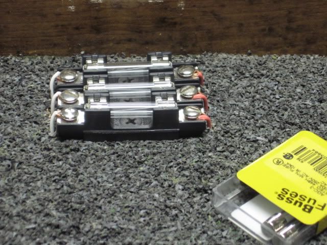
Another problem, that I also experienced with both the Atlas and Ross power routing, is that, all those wheels rolling through a relatively close tolerance track set-up on any switch will eventually cause a short, no matter the switch or the wheel sets.  Eventually, after I returned a couple of fried 6924 relay boards, I added (3 amp fuses) to the power routing circuits. Atlas added the (3 amp fuse) to their on-line diagram for Power routing.   I also added (3 amp fuses) to the Ross/DZ power routing circuits, Fort Pitt High Rail layout.  Sure enough, fuses have to be replace periodically.  These shorts at track amperage, IMO, can easily fry such a small relay as the DZ 1008, if they fried an Atlas 6924 relay board rated at 8 amps.  IMO.
Power routing was added to both these switches. Note the pens.  The distance between these two switch centers, (dead spots), matches a couple of my long connected E8's.

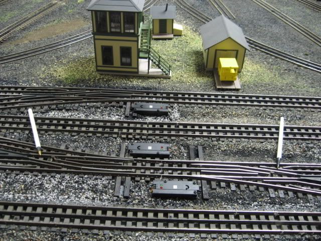
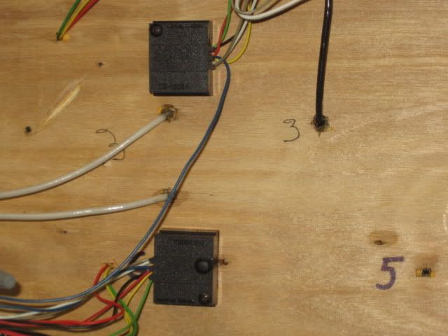
The newer DZ1008, with the leads, can easily be installed under the table.


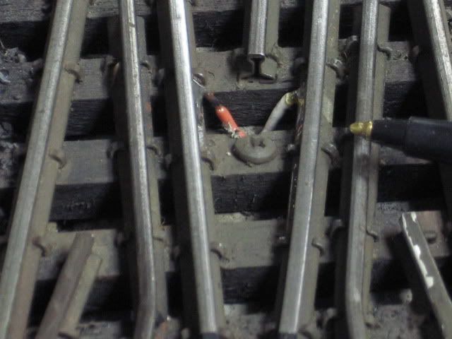
Power routing wires added to the dead rails center of switch. Grey/(or tan) and white wire from the relay.  The white from the relay is connected to the red, attached to the rail in this picture.  Grey/Tan from the relay is connected to the white, attached to the rail in this picture.

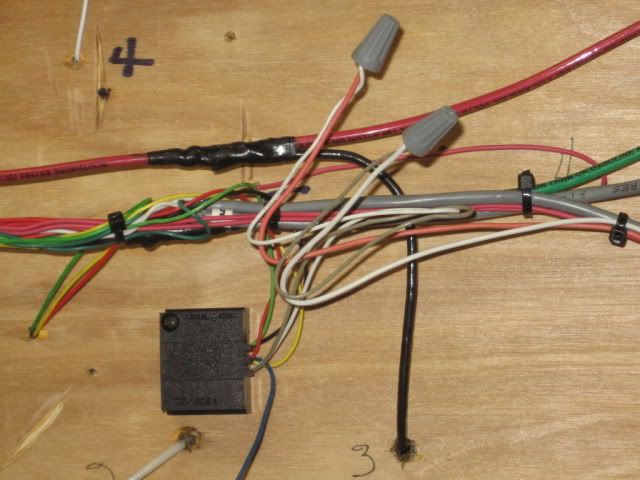
The Fuses were mounted on top of the module, easily accessible, so that they could be replaced.  Added ahead of the blue wire on the DZ 1008's pictured above.

IMO same applies to the relays used for power routing on the double slip, IMO.

Last edited by Mike CT

I did the same thing.  Have the relays wired with the same type fuses you are using and have the rely and the fuse located so they are easy to access.  The DZ1008 contacts are rated for 10 amps but.....   Anyway., I use 6 amp fuses.  So far have not had to change any and have not lost any relays.


Initially, I was having so much trouble getting my two double slip and other switches set up that I built a little relay test board with a known good DZ1000 so I knew for sure if relays were good or bad before installation.  Also, use it to test a suspect rely off line.  Just connect yellow, green, red and black relay wires, hook meter to the blue and white, power up and start pressing the buttons.  Have never found a bad new DZ1008, but did weed out about 8 or so that I fried myself wiring incorrectly.


Relay Test

Attachments

Images (1)
  • Relay Test

Many thanks for your suggestions and ideas. Now that it's the weekend, I can check them out.


Mike, where is the Fort Pitt Highrailer layout?  I live in Washington Pa and would love to see it. Looks very cool!


Is there any chance you're going to the Greensberg show tomorrow? I can't remember if it's the Fort Pitt Highrailers who have a demo layout there. I'm planning to go.


Tom

Problem solved! Many thanks to all who responded, especially Bucky for his clear advice and patience. Turned out that one of the relays was bad. Tested a new relay and installed it this evening. Locos now go through the 2B slip switch at low speeds without stalling out.


This is a great relief! This problem has been bugging me for quite a while.


I'd still like to take a look at the Fort Pitt Highrailer layout...


Thanks to all!


Tom

Originally Posted by Mike Miller:

I'm in the beginning stages of laying track for my new layout. Would it be better to wire the relays to the slip switches before I install them or after all track work is completed ?


Mike  

I would wire the entire layout and extensively test everything by running an engine whose pickup rollers spread was such that it will pass through all turnouts without stalling.  After everything else is working fine, install relays where needed for the short pickup spread locos that can't make it through.  I installed a couple relays on slip switches during initial wiring and then while testing the rest of the layout made a mistake and ran some rolling stock through a slip switch forgetting to turn on power to the switch machines/relays.  Lost a couple relays that day.  As mentioned above, it is helpful to mount the relays in a location where they can be easily reached if one needs to be changed out.  The fuse idea is good, too.  I did both these things AFTER that incident.


It sounds simple enough to keep wiring "sorted out" as you lay track, but be diligent.  I ruined some things when I accidentally connected a hot lead for turnouts/relay power to the track buss instead of the one for the switches.

Add Reply

Post

OGR Publishing, Inc., 1310 Eastside Centre Ct, Suite 6, Mountain Home, AR 72653
800-980-OGRR (6477)
www.ogaugerr.com

×
×
×
×
Link copied to your clipboard.
×
×