
I have approximately a 14 foot by 8 foot area to work with.  I want to build 2 levels and be able to get my engines up and down.  I am curious to know what peoples opinion is on the best grade.  Obviously if you have 40 feet you can make it that long, but I dont.  But i do want it to look nice.  If I have about 6 inches in between level 1 and level 2, what is the grade that would best suit me.  I have many Lionel engines and an MTH Z-4000 transformer, so the power is there.  How many inches do I need to make the grade to make it look nice?


Thanks,

Frank

Original Post

Replies sorted oldest to newest

A lot. In short:
A generally accepted max grade is 4%
That is 4" of rise in 100" of run
If you want to elevate to 6"" - your run is 150"
You also have to calculate in your substrate or bench work for the 2nd level.  Another 3/4" or similar.
You can do it in 14' by starting a switch on a corner and running it almost the full length on the outside in the back of the layout.  If you follow me.  It will take a track on the outside just about the full 14' to pass over the first level.
This is a 3.8% grade as William mentioned. It takes the most of (1/2) the outside loop on a grade (up) to combine the two levels. Close to 131" to rise 5".  Same amount of space for the second grade (down).

Down

The grade continues, off the deck bridge, around this O54 curved end of the layout.

Most of the outside loop is either up or down.
Last edited by Mike CT
Originally Posted by Rail Dawg:

What about having one track grading upwards while the other grades down?


You could cut the distance needed by half?


Chuck

You and I are on the same page on this one. If it will take a 4% grade to go from 0" to 6", you can use the same distance with one track going from 3" to 0" and the other going from 3" to 6" at 2% each. From a build standpoint it's a bit more difficult, but from an aesthetic point, it's a more attractive appearance. From an operational point it's better for the equipment. The catch is that this approach would have to be compatible with the purpose of the grade in the first place.

Originally Posted by goaliefp:

Thank You to EVERYONE for the advice.  I was just curious about Chucks suggestion.  I dont understand how that would work.  Can you explain more or put it in picture?


I greatly appreciate the help everyone!


Good question. This works if you have two separate lines and you are trying to get one over the other. One goes up at 2% for 50" and the other goes down at 2% for 50". You effectively have 4% grade between the two but the train only sees 2%.


I could have been more clear.


Chuck

Chuck,


2% up or down for 50" only generates a 1" fall or rise at the end of that 50."  If 50" out is where your separation needs to be, and the minimum separation is 4", then you still must have a 4% grade on each of the two 50" runs.  A 4" grade separation requires a 4% grade on either one 100" run or on two 50" runs of track (whether or not one goes up and one goes down.)


Another Chuck

I dont know why, I just dont understand "one going up and one going down".  I dont know why I just cant see it.  I plan to have 2 levels and want to be able to get trains up and down, but there will be about 6 inches in between the 2 levels.  so if you come half way down, its only 3 inches, then what?  i still have to go the other 3 to get to the other level.  I guess I just dont see it.


Are you saying that the main lines them selves go up and down?


BTW, Mike, Pics look great.  Thats the other thing I need to learn how to do, make mountains and tunnels.  I think ive gotten then bench work down.  I am not good at scenery at all!

best way to explain it would be instead of your base height on your fist level being 0" make it 3" that way your lower level can go down 3"to 0" and your upper grade can go from 3" to 6" giving you a 2 % grade on both levels but still giving you the 6 " of clearance needed for the upper level. but it only works in instances where the area at 3" above on lower level is not under the upper level at 6" because you would only have 3" of clearance there


Except that only works if you can go 100 inches in both directions.  But if you still have 100 inches to work with then the grade doesn't change, no matter where you start.  A grade is calculated by the height you go divided by the distance to go that height.  The only way to change that is to decrease the height or increase the distance to go the height. 

Let me offera  side view of all of this


 I have found 3% will allow  good running  up and down grade.  That said 2% Is a gold standard and a great  % age if  you have room.  I ran thge 3 % as  8' is 96" long and a 3" rise is a 3% grade.   Using this a 6 " clearance would be 100 inches or run.  


We offer a 99" run for a ramp and  curved sections at 31" to 42" to 54" and beyond.

99" ramp costs $121 +S&H Colors red , gray and Black.  Curve Are $55 for 90 degrees and $100 for 180 degrees of curves

We show  a photo log of the building of a module that is taken to train shows

Obridge L bridge construction time lapse [1)

Obridge L bridge construction time lapse [2)

Obridge L bridge construction time lapse [8)

Attachments

Images (3)
  • Obridge L bridge  construction time lapse (1)
  • Obridge L bridge  construction time lapse (2)
  • Obridge L bridge  construction time lapse (8)

PRR1950 and Sinclair,


I think you guys got it right for that situation.  Again, this is for when you have two separate tracks and you want one to go over the other (lower track goes down while upper track goes up).  I may be wrong (usually am), but I think we are confusing goaliefp.  His original post wanted some information about going from one level to another in the space that he had.


Again, William's suggestion to start from a switch on a corner and running it almost the full length on the outside in the back of the layout would be a good approach for goaliefp to get from his lower level to his upper level in the space he has.


Ron

Ron (CAPPilot),


Thank you very much for the explanation.  I agree with you I do think that is the best way to do it, and I was leaning towards Williams suggestion.  I do think I can handle building that. 


On the flip side, I do appreciate ALL of the other suggestions too.  Im only a year and a half into collecting and railroading (unless you count when i was a kid and just put my dad's O27 track together and pushed the cars around without engines ;o)


So all of the suggestions help.  I will have to keep looking at pictures online and see how this up and down thing goes.  Im intrigued by it.  If I build a certain wait, I MIGHT be able to pull that off where I dont need to go the whole 6 inches up.  I kind of like the idea that maybe I can go half way, and the portion that needs to go under can go down the 3 inches in order to fit under the upper level.  I like it.


Thanks to everyone.  This site is awesome.  I love just coming on and reading as much as I can and appreciate everyones help!

Originally Posted by goaliefp:

Thank You to EVERYONE for the advice.  I was just curious about Chucks suggestion.  I dont understand how that would work.  Can you explain more or put it in picture?


I greatly appreciate the help everyone!

Sorry for not being clear. A picture is worth 1,000 Words.


Basically, your "base" elevation is raised from 0 to 3". Then you have one track ascend to 6" while the other descends to 0" at the point one track crosses over the other. This way the train(s) will only have to deal with a 2% grade instead of a 4% grade. This works particularly well with two-lap ovals. If you can sketch out your plan I can get an idea of what you're trying to do, because this technique isn't applicable to all layout types.

Grade Separation Example

Attachments

Images (1)
  • Grade Separation Example
Originally Posted by Jhainer:

4% grade from0" to 6" in height would require 150" or

2% grade from 3" to 6" in 75" and 3" to 0" in 75" for 4% grade overall 2% on upper and 2% on lower

But it isn't 2% on the upper and 2% on the lower, it's still 4%, 3"/75"=.04=4%.  Think back to your algebra days, the grade is the slope of the line.


Originally Posted by AGHRMatt:
Originally Posted by goaliefp:

Thank You to EVERYONE for the advice.  I was just curious about Chucks suggestion.  I dont understand how that would work.  Can you explain more or put it in picture?


I greatly appreciate the help everyone!

Sorry for not being clear. A picture is worth 1,000 Words.


Basically, your "base" elevation is raised from 0 to 3". Then you have one track ascend to 6" while the other descends to 0" at the point one track crosses over the other. This way the train(s) will only have to deal with a 2% grade instead of a 4% grade. This works particularly well with two-lap ovals. If you can sketch out your plan I can get an idea of what you're trying to do, because this technique isn't applicable to all layout types.

Grade Separation Example

But for this, you are increasing the distance to go the height.  As for it only working in some layout types, I guess I would need to see a layout where it does work and one where it doesn't work.

Back to the original question -- William's suggestion is the simplest and clearest without seeing your track plan. But it is important to try NOT to have any curves on a grade as steep as 4%. In other words start and finish your grade on as much of a straight as possible; 1 to 1.5 car lengths is a minimum if possible even if it means a little steeper grade. Curves before, after, and on steep grades are invitations to derailments!

For a real life situation, i happen to have a a 4.17% grade in about 10+ feet of space to get 6" of clearance over the track below it. A Railking PA (downgraded to one can motor) will pull a Railking PB and 6-7 KLine 13" Streamliners up it with no effort. The only trouble i have ever had is fast starts on the middle of the grade can cause throwing of a traction tire.

Good luck.

jackson

Originally Posted by sinclair:
...

Sorry for not being clear. A picture is worth 1,000 Words.


Basically, your "base" elevation is raised from 0 to 3". Then you have one track ascend to 6" while the other descends to 0" at the point one track crosses over the other. This way the train(s) will only have to deal with a 2% grade instead of a 4% grade. This works particularly well with two-lap ovals. If you can sketch out your plan I can get an idea of what you're trying to do, because this technique isn't applicable to all layout types.

Grade Separation Example

But for this, you are increasing the distance to go the height.  As for it only working in some layout types, I guess I would need to see a layout where it does work and one where it doesn't work.

The distance is the same in both illustrations. It's applicability depends on the layout type which is why a sketch would be helpful.

Thanks everyone for helping to explain what I was incapable of doing.


I'm in the process of designing a 22 x 30 layout and it's incredible the amount of forethought that has to go into something like this. Back in the early 90's when I built a large HO layout the internet for the general public was just starting and it was very hard to get the expertise shown on this forum.


Nice job guys.


Chuck

Last edited by Rail Dawg


Hi goaliefp

Is 14' x 8' the layout space or the room size? It is nice to have at least 30" of walkway space and to try to limit the reach to 36".


The reason I ask is that if you are willing to make a mountain at one end or near the end you can use a helix to change levels and hide it in the mountain.


The width of the turn radius at the end will determine how wide the helix would need to be.


Also when you include a helix, a reverse loop of some type is needed to turn the train around to change direction on each level to get back to the other level.


Here are pics of an example. It needs 74" long by 60"wide plus scenery material and uses 228" of track to climb 7" for a 3.5% grade. That allows for at least 5 3/4" clearance allowing for rail height and deck thickness. It is an 054 circle with 15.5" inches of straight to make the oval and add track length.

Attachments

Images (2)
  • 054 helix
  • 054 helix 3D
Last edited by Moonman

14 X 8 is approximate layout space.  I actually can probably go to about 15' X 9'-10' max for the layout space and still have some walk space around.  I actually have 17' by 10' of a 3 wall area that is open on the 4th side (the other 17' side). 


Maybe some of you can help me with the layout design.  Ive been looking all around for something I like.  The thing is, I have 2 steamers that need O72.  So my initial thoughts were this...


Having 2 ovals.  one essentially above or just outside the other.  My upper level would be inside with O84 and O72 track.  2 main lines.  Lower level will be the same curve wise, but I could put some straights in at the ends to have 2 main lines on the bottom level as well, extending just outside the edge of the upper level.


I do have room to have an L stick out at the end (only enough room for a yard as I couldnt have it turn around.)


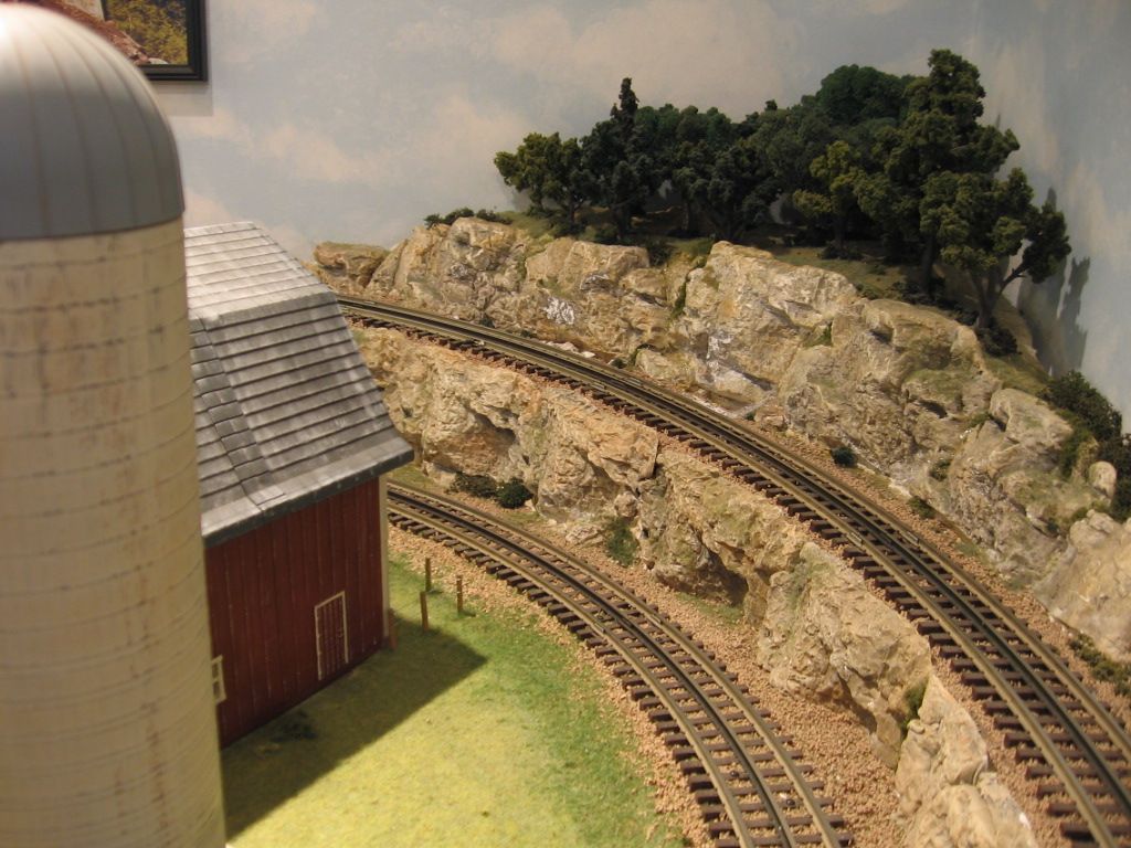
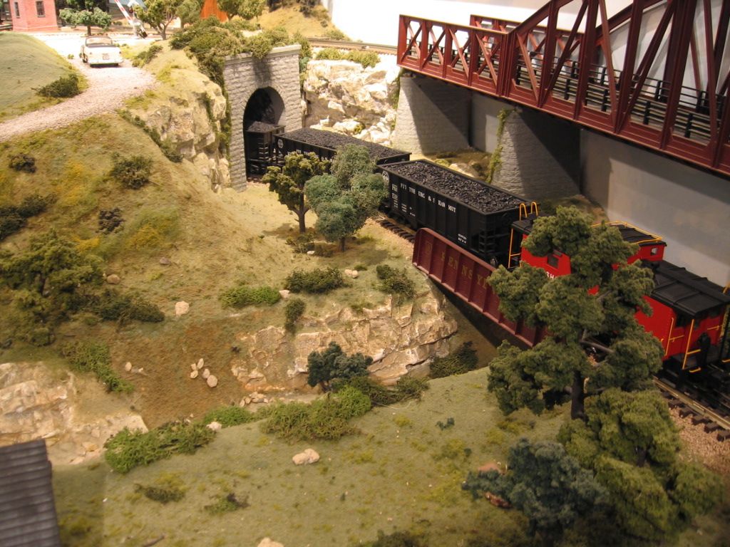
I also have O36 and O48 track that i can put another main line on the lower level inside the O72.  Again I would love to have some mountains but have yet to learn how to make them.  I am pretty much reduced to drawing lines on paper to get my ideas, and viewing online pictures.


if anyone would like to help me with a plan with all of that in mind, that would be phenomenal.  For the record I have all Lionel Fastrack. 


Also, I would consider Moonman's suggestion of a helix if I could do it possibly with the O72?  or would you all suggest I buy some O60 just for the helix?


Im open to any and all suggestions and greatly appreciate all the pictures and words above!!  Thanks!

I would suggest that the original poster set up some temporary tracks to test his own loco and train performance on the projected grades, before committing to build a substantial layout with those criteria.


I've used grades as steep as 8% to connect a floor layout with a table layout, but I have only two Magna-traction locos that can haul a train of any length on that grade. It's a challenging and interesting operation, but just a sideshow to my main layouts.

hey goaliefp,

Gave it a try. It looks like you would need a 9' x 16' table to have a large radius (084 lower\072 upper) double oval. The helix is 072, rises to 7" with a 3.2% grade.


Getting a reversing track in there causes the need for width.


This design will fit on the 14' x 8' table, but will limit you to small scale engines and cars and traditional or semi-scale because you would have to use a smaller radius reversing track. The lower would be an 084 loop, the upper an 072 and the reversing pass smaller. All 072 switches. (Right side of track plan).


So, depends on what you want to run or the maximum space that you have. Seems that the space is the given that will force you to run less than scale engines if you want the ability(druther) to go from level to level.


It's all give and takes.

Attachments

Images (3)
  • goaliefp 9 x 16
  • goaliefp 9 x 16 3D
  • goaliefp 9 x 16 3D 1
Last edited by Moonman

Guys, you can't fight the math here!  You're confusing grades with absolute clearances.  For the latter, you need 6".  How you get the 6" clearance depends on the benchwork/tabletop design as well as the layout design.


If you're starting with a plywood base of 0", then you're stuck with steep grades.  However, if you "elevate" the base plywood level to 3", then you have the potential of designing your layout so that when trains need to cross over each other, a portion of the grade can drop 3" AND another portion can rise 3" to yield the required 6" clearance.


Depending on your layout's design, the casual observer may no longer be able to easily "see specific levels", rather they'll see various portions of the layout rising or falling to achieve the appropriate clearances where tracks cross over/under each other.


For folks who start with a table-top railroad, this is not an intuitive concept.  But for folks who plan ahead with open grid or L-girder benchwork, it's easier to visualize the potential of having trains cross over/under each other with more gradual grades.


Hope that helps.


David

Originally Posted by Jhainer:

4% grade from0" to 6" in height would require 150" or

2% grade from 3" to 6" in 75" and 3" to 0" in 75" for 4% grade overall 2% on upper and 2% on lower

Right idea... but bad math!!!  


By raising the layout's "base" to 3" in height (from the benchwork girders), you now have the potential for a portion of the grade to drop 3" and another portion to rise 3".  Depending on your track plan, you may be able to achieve the required 6" clearance with more gradual grades.  


In the example quoted above, a 2% grade for a 3" rise requires 150" -- not 75".  But with open grid or L-girder benchwork, you now have the ability to use the full 150" for both a 3" rise AND a 3" drop.  So you've effectively achieved the 6" clearance using only a 2% grade -- but with 300" of linear track.   Get it?


But if the plywood is at level 0", the 6" clearance requires an all up-hill rise of 6" in the 150" of linear feet, which is a very steep 4% grade.  Workable for a toy train layout, but much less desirable in environments where long freight and/or passenger trains will be the norm.


David

Last edited by Rocky Mountaineer

goaliefp,

It's only a concept. You'll have to put something like that against the walls in 9' x 16'.

I wanted you to see how much space was required to do that in 084\072. If you do build it that size, you'll need access hatches in the table.


You really have an 11' x 7' layout area with 36" of walk around space. Any smaller walk space will get annoying real fast.


If you go around the walls and across and access the open space with an lift sectionand 36" wide tables\deck you can have a double main 084/072 and be able to add other elements. You could then elevate and drop the outside line against the walls in 37' for show if you want that effect.

Attachments

Images (1)
  • goaliefp aroun the walls
Last edited by Moonman

Per Frank's suggestion regarding dimensions of layout:

What 9x16 looks like in flat track benchwork [actual 9'-2" x 16'-0"]. Right side is 40" wide for Service Yard, left side 36" for Village. Dual main is 084/072 in hinged Drop Section and is 096/084 at other end.

Objective was maximum curve arcs in limited attic space. Just running and no duckunder!

100_1304-001

IMG_1918-002


IMG_1634

Attachments

Images (3)
  • 100_1304-001
  • IMG_1918-002
  • IMG_1634
Last edited by Dewey Trogdon

Add Reply

Post
The Track Planning and Layout Design Forum is sponsored by

AN OGR FORUM CHARTER SPONSOR

OGR Publishing, Inc., 1310 Eastside Centre Ct, Suite 6, Mountain Home, AR 72653
800-980-OGRR (6477)
www.ogaugerr.com

×
×
×
×
Link copied to your clipboard.
×
×