
I was sent two diagrams to explain the wiring of the DZ-2500s to the Ross 3-way; one was the 3-way using DZ-1000s and DZ-1008s and the other was the X-over using DZ-2500s.
 
Neither of these are easily merge-able into the solution; HAS ANYONE WIRED a Ross 3-way using DZ-2500s and DZ-1008s that could then share a wiring diagram with me?? I have sent an email to Steve at Ross Custom but I have not received a response as yet.
 
Still trying to understand the 3-way connection to the two DZ-2500s. The diagrams for the 3-way show flipping the A & B rails  power to ground; while the X-over shows the 1 & 2 rails going from power to no power.

Thus I see that I must flip the power/ground on rails A and B depending on the direction out of the switch. got that concept.

However it appears that I will need one DZ-1008 for each DZ-2500 so that the power/ground can be flipped on the A&B rails depending on how the switch is thrown. Do I need two DZ-1008s?

Actually only one of the A B rails needs to flipped in an either up or down switch position and that would be power; at a straight thru position both A&B rails are ground.

Here is my problem,assuming two DZ1008 relays what is the relay-trigger position wire on the DZ 2500s; for one it would seem to be the green wire and that is reversed on the other DZ-2500 where it would be the yellow wire. Correct.

Trying to not keep doing this on a trial and error basis.

thanks in advance.

Original Post

Replies sorted oldest to newest

Alan:

I am still in wiring mode but I use DZ-1000's. So given that:

1- I believe you need two DZ-1008's. One to turn rail A on and off and the other for Rail B. You can't use only one 1008 since each is connected to its own DZ-2500. 

I guess one could rig up a connection scheme so that one 1008 is connected to both 2500's but what happens to the 1008 when both 2500's are controlling it is a question for Dennis Zander (Z-Stuff).

Incidentally you may want to try contacting Dennis. He builds the 'stuff'.

Two more comments you best check with Ross or Z-Stuff:

1- I have the three way but it is not wired yet though I seem to remember bench wiring it. I seem to remember that for either motor to throw the rails into a curve the entry rails have to be in the straight position to start with. In other words one motor does not have enough power to push its rail and the other motor's rail to one side (hopefully I said this correctly).

2- If after wiring everything, the 1008 does not function properly check out the red (green?) LED on the 2500. Pull it out and see if the 1008 functions. There was an issue with 'leaky' LEDs - I know for a fact on DZ-1000, whether it crossed over to the 2500 I am not sure. Dennis will replace any bad ones. 

Joe

 Yes I have two of them. Also non-derailing  works for all three track turnouts. Because it is possible to throw the two 2500Cs in a way that will lockup the switch (You can unlock it)  I activate the switch from the three non derailing rails with a three-way single pole momentary custom switch.

FIRST  you are better off with  4-way  but if you must have a 3-Way then you need:

1) 4 diodes; and

2) 2 DZ-1008A SPDT Relay Modules. 

3) you need to have way to change the polarity of the center 2 steel (non-blackened) short straight rails using the relays because in the straight position they are outside rail connected; and in the left or right position they change to the center rail polarity.

4) The diodes like all diodes prevent current from going the wrong way which is important for the center position that receives current  when triggered by two different DZ-2500C  combinations again that is why I use the non-derailing rails to control the two DZ-2500Cs

Preview attachment 20180916_151955_resized.jpg


20180916_151955_resizedPreview attachment 20180916_152001_resized.jpg
 I have the switch remove because I am do some other work in the area. This is the underside of the switch. this 3-way switch is elevated so I created some piping, several junction boxes and truss framing to hide the relays and wiring. It is not that complicated. The piping was created on my 3D laser printer.
 
20180916_152001_resized
Preview attachment 20180916_152013_resized.jpg
 Here is a close up of the non-derailing wiring showing two of the diodes and wiring
 
Preview a20180916_152013_resized
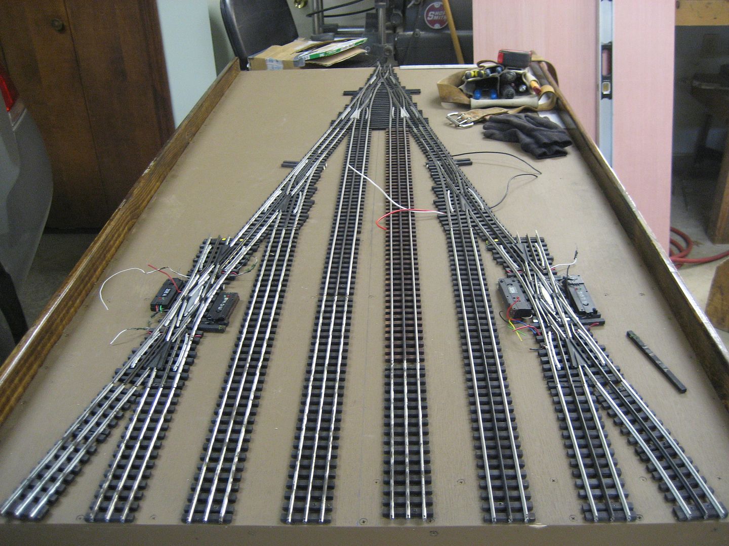
ttachment 20180916_152140_resized.jpg
 Here are the two relays inside the truss framing.
 
20180916_152140_resized
There is a some wiring and the other two diodes contained in the wiring junction boxes.
The wiring diagram I seem to have left at work so OI will post it in the next few days.
20180916_152140_resized.jpg
582 KB
 
20180916_152013_resized.jpg
508 KB
 
20180916_152001_resized.jpg
594 KB
 
20180916_151955_resized.jpg
462 KB


Attachments

Images (4)
  • 20180916_152140_resized
  • 20180916_152013_resized
  • 20180916_152001_resized
  • 20180916_151955_resized
Last edited by AlanRail

Done with DZ 1000s. Key on the non-derail sensor sections is that the Center track requires two sensors, one for each of the two motors, required for this switch.  I had to move the sensor section, for one motors, further back away from the frog.   Here is the operation of two of the Three  way switches.   Click on the triangle to access the video.  Note the switch point flicker indicating, the switcher has not cleared the non-derail sensor section.  There are DZ 1008 used to power route specific dead rail sections, they were not used as part of the DZ 1000 control. 

Last edited by Mike CT

Video shows a Rich Yoder 44 tonner with an early ERR upgrade, electro-couplers and sound.  Three way switches are #4's matched to existing #5 switches that we (Fort Pitt Highrailers) had.     Here is a link to the module rebuild. 

Slideshow of the rebuild. 

Another project was a yard ladder with an older Curtis/Ross switch and a couple of double slips.  Double slips also a two motor switch.   

Click on the underlined phrase to link.   Module are 6ft (length).  There are two additional modules as storage tracks for Fort Pitt Highrailer member trains.  

Last edited by Mike CT

Add Reply

Post
The Track Planning and Layout Design Forum is sponsored by

AN OGR FORUM CHARTER SPONSOR

OGR Publishing, Inc., 1310 Eastside Centre Ct, Suite 6, Mountain Home, AR 72653
800-980-OGRR (6477)
www.ogaugerr.com

×
×
×
×
Link copied to your clipboard.
×
×