Well, finally completed (for now) the drawing with SCARM of my layout.  Although not complete, yet, this is a view of what I am trying to complete and someday have looking more detailed and run trains in operating sessions.  But, in using the SCARM format, still having a few issues... one being notation of track elevations per the program.  However, use of the text format does make it fine, just need to complete with proper designations... and learn to make use of the layout "outlines" of the table shape.  Progress is slow at times, like climbing a 3% grade and being underpowered.  Hope you like and looking for comments/suggestions from fellow Forum members.

Thanks...

Jesse   TCA  12-68275

Attachments

Files (1)
MOKATX layout in SCARM
Original Post

Replies sorted oldest to newest

Hey Jesse,

Whew! Lots of track - quite a layout!

I brought some order to the chaos. Put everything at zero elevation and organized the tracks and objects into layers to provide ease of viewing/working.

SCARM does not allow negative track elevations. Objects, yes. The lowest track will be zero and everything can index from that point. The main reason to do that approach is the terrain and 3D follow easier. You can do it by setting the baseboard/table height at zero, and everything else of an object for a deck, but it creates many hours of work to manage the 3D.

So, 0" would be the -4" area of turquoise track, I believe. So, it looks like turquoise would be zero rising to 13 (-4 to +9) at the wye for the base track. The purple would +4. So, you see, add 4" to all of the marked elevations.

The next concern is the layout is larger that your desired area. I added a 28' x 24' baseboard and moved everything within that.

There's a lot of fitment issues, unconnected track joints for length and/or alignment. I didn't tackle that because of the table size issue.

I added a some compass to provide orientation reference.

Try the layers function and practice on that.

Do you want this fit into the 28' x 24'? let me know and I'll go the next step for you and correct the fitment and set the elevations. It's a complex layout to be learning software on. I attached a working file. Right click and save as to your computer. Then check out the 3D and Layers in 2D.


Attachments

Carl - Thanks for the fix and input on the layout in SCARM.  Fact is, this is an existing layout, not just a design.  It is in process of being built to completion, but the track is in place and being completed in roadbed and 3R ties/ballast.  I admit the SCARM may not be to scale, exactly.....  Honestly, I am happy just to now have an organized "layout" of the MOKATX train layout, not simply the hand drawn and colored representations I have had prior.  Again, thanks much for the information and input to this.  One more example of the reason and benefit of being a member of the Forum and correspondence with others in our wonderful hobby and common interest.

Alex - Yes, the layout table/support is already constructed and I did so at the 27" elevation after much consideration.  One, it makes for easier reach across the top of the layout for access, easier reach under the layout for working as I lay on a "creeper" and have a comfortable length of arm reach for wiring and all else. And so much easier on the neck!  Also, it allows for later planned elevation increases, keeping them within comfortable reach/access and ease of viewing along with completion of detailing/scenic applications, etc.  Yes, I have considered raising the layout height at one time, but decided not to as outlined in the previous explanation.

Thank you all for your input and discussion, and interest.  I know I am not alone when I say I do have hopes of this being my last layout build.  It is the largest I have ever been able to do, and one I have hopes of completing to final stages of detailing and scenery.  Of course, one is never really complete of all detailing, as we all know.  The one goal I do have, to some extent, is to be able to have all my rolling stock/passenger out of boxes and "on display" on layout trackage (classification yards, etc.).  However, that is a pipe dream of sorts, not near enough room, would be pleased with at least 50% on tracks and remainder on wall mounted shelves/display cases under layout perimeter.

Always have a goal, no matter how far it may be........

Jesse       TCA  12-68275

While it might be possible to lay on your back and work underneath a tabletop that is only 27" high, it's not going to be very practical. I'm also concerned about the duck-under even though it's at ~36" high. In both cases, that height is misleading because there will be framing below in the 3.5" range, making the effective heights ~23"/32".

The other concern is reach. Even if there is access on all 4 sides, I'm having a hard time envisioning access hatches, particularly for the area around the passenger tracks. I'm also having a hard time envisioning the "peninsula" for the turntable, I only see it as a bump-out.

The purple run looks unfinished and there appear to be too many tracks to/from the turntable and no whisker tracks, so it looks like some work also needs to be done there.

Anyway, I played around a bit with Carl's version mostly to show you how to configure the baseboard to get open areas. As currently configured and as Carl mentioned, the track fills a space that is 24'x30', so some work will need to be done to shrink it to fit 24'x28'. I attached the layout file, but only for you to see how I did the baseboard, not to be used as a working file or to supersede your file or Carl's file.

Capture

Capture


Attachments

Images (2)
  • Capture
  • Capture
DoubleDAZ posted:

Carl, what kind of grades did you come up with?

Everything is under 1.9% except the yellow mountain climb which is 2.9%. I'll have to check it, my eyes were blurring and I may not have adjusted it.

I zeroed the -4 corner and built it with his elevations. Then used the whole change trick and added 4 to everything but that undertable corner. It's all tunneled in the NNW traveling E to 5".

I'll shoot you the file for fun sim.

Last edited by Moonman

Gentlemen,    All I can say is thank you so much for the input and fine work performed in SCARM.  I would love to be as proficient in SCARM, on a computer, as you are.  Since retirement I have not had as much time and usage on any laptop as before with my employment, and I have lost the ability I once had.  This is one reason, again, for the Forum and it's great members.

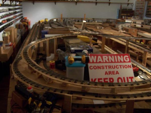
Dave, yes it would be a very low duck under, in the normal sense.  To assist with clearance, I make use of a "sit on" creeper to make my way under the wye bridge.  The hardest part, now, is getting my knees to cooperate sometimes.  But, that is a daily adventure in itself on some days.  Also, your baseboard is very close to what I have set up.  There actually is more room to the South of the turntable, hope there is enough for a small roundhouse, definitely for fiddle tracks.  Also, the location marked as "small airfield" is currently also open, with bridges for the two tracks from the East side of the turntable, heading to the South.  The airfield will be on a lift out, possible a "fold down" hinged off the table either East or West of it.  I did try the baseboard function to show this, but as with other, did not have the time to put into it of late and figure this out.  The layout table is actually 28 ft on the East side, tracks as I drew them are possibly a bit too long in the S to N direction.  I could make it 30 ft long, but would have to do away with some shelves, work areas, and access on the South side would be way tooMOKATX layout lift section down positionMOKATX layout West sideMOKATX layout South center elevatedMOKATX layout NW quad overunder tight.  I have access on all four sides to reach across, and with the 27" height, I have no great difficulty reaching to most all points.. so far.  I have posted pictures of the earlier progress as track was first laid down... somewhere in the Forum posts.

Carl-Moonman,  Yes, it is a lot of track, most in Lionel and K Line tubular.  As with Elliot, have a lot of track left from prior layouts and what I gathered in recent years.  Also, not shown as such, the majority of the purple line is Gargraves track and switches, some tubular intermingled as needed. Also, the purple line is strictly for services areas and making up passenger consists.  I do have a lot of Atlas track, switches ( #5 mainline, 072 wyes, double slip-switch, etc.) shorter and long straights, and 072 or greater curves.  These I have reserved for the upper level (to be constructed) classification yard, to be located over the West side of the layout.  This is to be accessed from the 16" elevation East side yellow line.  I like the way, on 3D, you show the blue line as in the open on the SW corner.  I was thinking of having it in a long tunnel, exiting out onto the elevated wye... aka Feather River Route.

When I can, I will get up to the layout and take more exact measurements of the layout table, though I have done so several times, never seem to locate where I have them, now.

Jesse     TCA  12-68275

Attachments

Images (4)
  • MOKATX layout lift section down position
  • MOKATX layout West side
  • MOKATX layout South center elevated
  • MOKATX layout NW quad overunder
Last edited by texastrain

Jesse,

I don't think it's a software problem as much as it is a screen size problem. I work on a 30" monitor and this was tough to navigate. Thank you for the photos.

The only problem I see that you had was with the blue being a little too much South may be a straight track and the angle of the yellow line turning in the Southeast setup the cross and the mountain too far North.

I think you did well if you created your SCARM file on a laptop screen. I have a 17" screen on my laptop and it's tough for me when I go to a client location. learning to set and tweak elevations takes a while, no matter which software you are using. A multi-level only makes it tougher.

I see the purple is under development. What I have put in will build as you see it.  I tied the run to the Backshop with a switch to the TT. It seemed like a long way to go to not to be able to cross or turnaround after traveling from the SW.

When I moved everything to the larger table in SCARM it put the yellow directly over the purple in the East. I went with it and used arch supports and gave it an El treatment like a city train. I could then see that there is space to move it East in between lines, but it wasn't necessary for a 3D peek.

Did you use a wye or is it really a three switch wye for the blue line aisle crossing?

Any chance you could post a photo from the SE looking N and one looking W? Then, I can adjust the file to be closer to your as-built.

You know, I forgot to mention something...I took the back and arms off of an office desk chair (one with a six-wheeled base) and lowered the seat for use on working on my motorcycle. Jesse, that may be a lot easier for you and they scoot really well. I now use it for layout builds.

Alex (Ingenerio1) built a nice seat scooter for his under layout adventures. Check his layout build thread.

Last edited by Moonman
Moonman posted:

You know, I forgot to mention something...I took the back and arms off of an office desk chair (one with a six-wheeled base) and lowered the seat for use on working on my motorcycle. Jesse, that may be a lot easier for you and they scoot really well. I now use it for layout builds.

Alex (Ingenerio1) built a nice seat scooter for his under layout adventures. Check his layout build thread.

Sorry, I was thinking about the aisle...I spent many hours under a 24" table at the museum restoration on an automotive creeper - not bad for quick jobs

It was the getting off of the thing when I came out that was the issue after a long session - and team members that liked to throw things under the layout instead of in the trash that buggered the wheels.

Dave... yes, I started this build in 2010 before I retired.  It was only worked on when I was in town on 4 day weekends every two months or so.  It has gone through 3 diff revisions since.  The first was more like a modular type layout ( did think of doing that ) a bit like one we had when I was with the North Central O Gaugers club in North Lake County, Illinois.  That was when I worked Great Lake Naval Center back in 1999 - 2003.  But, I knew I never planned to remove this layout from the train room, and getting it down the stairs would be too daunting to ever do so.  I now work on it when I can... when storm cleanup and taking care of the animals allows time to do so more.  It is a great way to relax, and do find time to work on / fix engines I have with doing ERR upgrades, repairs on the CCII Niagara, build Gunrunner John components purchased to eventually use in certain engines, etc.  never have a lack of projects.  One reason why using SCARM has taken so long, though I started doing so last year.  But, I know many of our fellow Forum members have the same in their endeavors and lives.

Carl.... yes, have looked at Alex's layout and his progress.  He has done very well and he has demonstrated many great ideas and procedures.  Yes, getting up after time under the layout, getting off the creeper, is not as easy as it had been!  But, for working on wiring, etc. on the underside, it works very well for me.  Yes, the over aisle wye is made from three Gargraves switches, and the Gargraves is matched up with the tubular from there.  I have no doubt my SCARM has any lines too long, or angles not quite in correct correlation to others.  I once tried to do this with the older Atlas program I have, but the SCARM is so much easier.  But, I believe my attempt is only a fancy version of my drafting / hand drawn versions I performed at first when designing it.  Track has been laid as it fit into what was available, and not always to exact placement.  I have ran trains on all trackage, except the purple line under construction and design.  this I have done to check clearances, super elevations on curves, power distribution, etc.  I am still tweaking many areas, but the largest/heaviest of my motive power and longest passenger consists have all passed muster with track as placed.  of course, this is still to be tested when I began building tunnels and other landscapes.  I will check on what pics I have on file for the vantage points requested, or could take new........ LOL!

Again, thanks to all and the new motivation is appreciated to spend more time on nearing completion.... after placing more 3R ties and begin to ballast.  And, after I make up my mine whether I wish to paint the rail sides...... hmmmmmmmm.

Jesse    TCA   12-68275

Attachments

Images (3)
  • MOKATX layout East side: East side looking North
  • MOKATX layout North side: North side looking East
  • MOKATX layout West side looking South: West side looking South

Dave, you are correct.  However, I needed to do my layout in SCARM for a nice, somewhat scaled, diagram for reference as I design the future upper level classification yard.  This will be built out of Atlas track and is to be located 30" above table top, or 57" above the floor.  This allows for good viewing and reach, but still has good view and reach on lower level tracks.  The upper yard will be accessed from the East side "yellow line" and will elevate from 16" to the 30" elevation over a 16 ft. to 22 Ft. distance, depending upon SE to NW angle and point of access on the upper classification yard trackage.

Thank you for your input and comments, they are very appreciated.

Jesse   TCA  12-68275

Add Reply

Post
The Track Planning and Layout Design Forum is sponsored by

AN OGR FORUM CHARTER SPONSOR

OGR Publishing, Inc., 1310 Eastside Centre Ct, Suite 6, Mountain Home, AR 72653
800-980-OGRR (6477)
www.ogaugerr.com

×
×
×
×
Link copied to your clipboard.
×
×