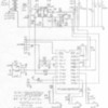
I came across a nonfunctional cw40, bit Lionel says they don't repair, just toss them and provide a new one for warranty work. I noticed there is one has a proprietary chip on the board, wouldn't be too surprising if that was bad. So, has anyone had any luck with Repair? It's so small, it doesnt seem worth much time or $ to repair, but I would at least like to give it one shot. Any schematics???
Replies sorted oldest to newest
Hmmmmm....never drew such a blank before �� So I will take that as a No and probably just toss it.....
I would toss it also.
The transformer core makes a great fixed voltage accessory power supply - especially for switches w/ LED lighting.
Just wire it directly to the binding posts for 17.9 volts output, the core should be able to deliver 4-5 amps, so a suitable breaker should be used too.
ADCX Rob posted:The PowerMax Plus is essentially half of a CW-80... w/ just 2.5 amps output and no programmable accessory output provision. Here is Dale Manquen's CW-80 schematic:
Follow his description HERE and you may be able to follow along looking at your "CW-40".
Dang Rob, that's great stuff! Thank you! It's probably still a sinker, but at least now I have several obvious places to go look! 2 fuses, one internal to the primary, other heat-shrinked on the secondary, etc.
I'll let you know what I find...don't hold your breath ![]()
GeoPeg posted:ADCX Rob posted:The PowerMax Plus is essentially half of a CW-80... w/ just 2.5 amps output and no programmable accessory output provision. Here is Dale Manquen's CW-80 schematic:
Follow his description HERE and you may be able to follow along looking at your "CW-40".
Dang Rob, that's great stuff! Thank you! It's probably still a sinker, but at least now I have several obvious places to go look! 2 fuses, one internal to the primary, other heat-shrinked on the secondary, etc.
I'll let you know what I find...don't hold your breath
And BTW, the microcontroller is still available, but only from an obsolete source component supplier - and when the price says RFQ, you know you aren't a player. Even if they would sample you just one, you don't have the bios code to program into the chip, assuming you had the means to do so. So that's a no-brainer if it comes to that...
ADCX Rob posted:The transformer core makes a great fixed voltage accessory power supply - especially for switches w/ LED lighting.
Just wire it directly to the binding posts for 17.9 volts output, the core should be able to deliver 4-5 amps, so a suitable breaker should be used too.
That reminds me of Dale M's testing of the hefty CW-80 transformer core. With the lack of PH180's it seems like one could make a suitable substitute with one of these cores and a PSX-AC for the fast breaker in an aluminum bud box.
If the fuse in the primary winding isn't bad, it's likely it's not actually the uP that failed, lots of other parts that see the power and voltage spikes that are much more likely to fail.
gunrunnerjohn posted:If the fuse in the primary winding isn't bad, it's likely it's not actually the uP that failed, lots of other parts that see the power and voltage spikes that are much more likely to fail.
I just completed my day at 6:30pm, up since 5am - mind you, I'm retired! Life doesn't always let you retire, does it? But anywho, my point is that in just a few minutes I get to pursue one of my favorite pastimes - repairing train stuff! I hope you're right GRJohn, I'll know shortly!
OK, primary and secondary good, fuses are all good, fan is running, and the 5v regulator is working like a charm. I checked for stuck buttons (direction, whistle, etc.) but none were. I grabbed my scope to see if the data lines were dancing and if the oscillator crystal was functioning, but alas! The my 30 year old B&K scope just died! I think that's a sign telling me to quit now. I guess I bought an 18volt, 2.5 amp transformer for running a few accessories. Can't win 'em all!
Thanks for the schematic, if nothing else, it helped draw a conclusion around this repair!


