New thread started for the continuation of relay talk from another control forum (to keep the hijack police at bay)

Original post

Stan here is what i can answer for you,

1. What voltage is your 8-channel module (5V, 12V, etc.)? 12vdc

2. Is it "hi" or "low" level triggered?  Or what is the eBay listing #. Ebay Item

3. These modules do not have any timing or delay to demote or mask intermittent axle contact (relay chatter) when the first few axles enter the block or when the last few axles exit the block.  Is this feature of interest - which would add, say, 25 cents per channel and assembling a few components (capacitor, etc.). Yes this feature is a interest, i think i can take care of relay chatter, but i wont be apposed if your going to draw something up to include them in the drawing.

Original Post

Replies sorted oldest to newest

OGR gets testy about direct eBay links, so I'd recommend you simply copy the description.

eBay item#: 231583189489

  • High Level Trigger.
  • 12V 8-Channel Relay interface board, and each one needs 50-60mA Driver Current.
  • Equiped with high-current relay, AC250V 10A ; DC30V 10A.
  • Standard interface that can be controlled directly by microcontroller (Arduino , 8051, AVR, PIC, DSP, ARM, ARM, MSP430, TTL logic).
  • Indication LED’s for Relay output status.


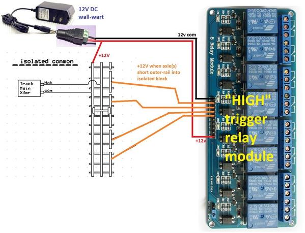
isolated rail 8 channel relay module HIGH trigger

If you have "HIGH" level trigger 12V module, you apply +12 to an input pin to trigger the relay for that channel.  The relay module is powered by a 12V DC supply.

The "trick" is to have an isolated 12V DC supply.  The + side of the isolated 12V DC is connected to the outer-rail (shown in Red).  This is kind of a mind-blower but the key is the isolation.  So when an axle(s) straddle the outer-rail into an isolated block, it sends the +12V to the corresponding input pin on the relay module.

For 8 channels, a 12V DC, 1 Amp wall-wart is suitable...about $2 free-shipping on eBay.

Once we "agree" on this concept, we can discuss adding capacitance to demote relay-chatter!

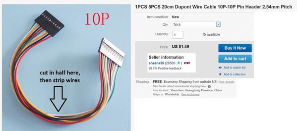
Also, that 10-pin "header" connection on the relay module can be made with a wire-cable from eBay:

10p header cable


Attachments

Images (2)
  • 10p header cable
  • isolated rail 8 channel relay module HIGH trigger
Last edited by stan2004

Interesting and mind blowing indeed! I would "assume" that if I found a low trigger I could share the grounds? (eBay item# 321355696979)

item description: 12V 8-Channel Relay interface board, and each one needs 50-60mA Driver Current.
Equiped with high-current relay, AC250V 10A ; DC30V 10A.
Standard interface that can be controlled directly by microcontroller (Arduino , 8051, AVR, PIC, DSP, ARM, ARM, MSP430, TTL logic).
Indication LED’s for Relay output status.

isolated rail 8 channel relay module LOW trigger

Correct.  The amount of wiring is essentially the same whether high or low level triggering.  I suppose it is easier to wrap your mind around sharing the Track Voltage Common with 12V Common but from an electrical circuit perspective they behave/function the same.  You have two separate, isolated, independent circuits that simply share the outer-rail - doesn't matter that one is AC and the other is DC...like ships passing in the night!


Attachments

Images (1)
  • isolated rail 8 channel relay module LOW trigger
Last edited by stan2004

I tried doing this exact plan (5VDC instead of 12VDC), but ran into issues (I think) because the DC was full bridged from the same wall AC source as the AC transformer. This caused 60Hz DC at approximately 1 1/2 times the AC voltage to flow through my low voltage DC electronics. After discussing on a seperate digital electronics form, I was pointed to LTV-844 optocouplers that could be wired directly to the insulated rail and then to the low voltage relay board.

Last edited by bmoran4
bmoran4 posted:

I tried doing this exact plan (5VDC instead of 12VDC), but ran into issues (I think) because the DC was full bridged from the same wall AC source as the AC transformer. This caused 60Hz DC at approximately 1 1/2 times the AC voltage to flow through my low voltage DC electronics. After discussing on a seperate digital electronics form, I was pointed to LTV-844 optocouplers that could be wired directly to the insulated rail and then to the low voltage relay board

Not sure what you mean by the DC was full bridged from the same wall AC source as the AC transformer.  Was the bridge attached to the track AC voltage and then a 5V regulator to generate the 5V needed by the relay module?  If so, then you did not have the signaling/relay circuit isolated from the track voltage circuit.

Frankly, if you go to a generic "digital electronics forum" there is not much knowledge about the somewhat unique situation of O-gauge track circuits.  The LTV-844 opto-couplers (aka opto-isolators) you mention are a way to create the isolation that is needed for the method under discussion to work.  The "problem" with using opto-isolators is you are isolating the track circuit from the signaling/relay circuit for each channel (each isolated block).  Not that the LTV-844 is overly expensive but why not just do the isolation in one fell swoop using an isolated 5V power supply (e.g., $2 wall-wart)...rather than doing it for each block?!  In my opinion of course...


christhetrainguy09 posted:

Well wouldn't the 12v to the common mess with the DCS and tmcc signals? 

The effect on DCS and TMCC signals is the same for attaching the +12V (red wire) or the +12V Common (black wire) to the outer rail.  In any event, the effect is negligible.  It has to do with the concept of a circuit.  That is, as the word "circuit" itself suggests, a signal goes out and comes back to make a "circuit."  Remember that the track power circuit and signaling/relay circuit are isolated.  Yes, they share one common wire (the outer-rail) so in basic terms this is only half of a circuit.  In other words the track voltage signal (and any DCS and TMCC) go out into the signaling/relay circuit but it does not come back because there is only a half of a circuit.  Because a circuit is NOT formed, current does not flow and hence there is no effect. 

This is a simplified description of what's going on from a network analysis (as taught in a college EE program) but suitable for the situation under discussion.

As mentioned this can blow your mind.  Might I suggest (if you have the high-level relay module in hand) you simply hook it up as shown and watch it work!  And I will show you how to demote relay-chatter (dirty wheels/track) with a capacitor.  Then, if all this is still just too fantastic, unbelievable, mind-numbing, or whatever then we can switch over to the low-level relay module, move some wires around, and carry on from there! 

Last edited by stan2004

I believe the issue was that the "wall-wart" is not isolated from the transformer. I just conducted this test:

Step 1

LW Providing 14VAC

Tyco (Wall-Wart standin) - Not connected to track.

Volt Meter Reading 14VAC

Step 2

LW Providing 14VAC

Tyco (Wall-Wart standin) Providing 18VDC

Volt Meter Reading 18VDC across "isolated" power supplies


Attachments

Images (2)
  • mceclip0
  • mceclip1

Yes, you can experiment with a 5V low-level relay module.  Obviously you need to power the relay module with a 5V DC wall-wart.  Confirm a relay indeed clicks "on" when you apply DC common to the corresponding input pin. *** Edit: see footnotes ***

Then to mess with relay chatter (dirty wheels, axles, whatever) insert a resistor and capacitor between the isolated block and the relay module input:
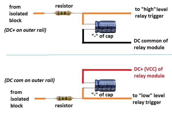
isolated rail rc filter

The R and C values are not that critical.  Something like 22 ohms (1/4 Watt) and 47uF (25V or more) would be a good starting point.  This will demote chatter in the fraction-of-a-second range typical with intermittent wheel-track. 

Note that the eBay relay modules have a transistor amplifier on the control inputs so that you can trigger a relay with far less current than if you directly drive a relay coil.  This allows you to use a relatively small capacitor; that is there are several circuit diagrams floating around using R and C to de-chatter isolated rail relays where the DC relay coil is directly attached to the isolated block via a diode.  In that case you typically need capacitors in the 100's or 1000's of uF (larger and more expensive) to be effective for intermittent wheel-track issues.

 *** Footnotes

1. I simply ask you (or anyone) to double-check the high vs. low functionality of the relay module before embedding it.  That is, I was looking at the photos in your high-level relay module eBay listing and I'm convinced it is showing a low-level module based on component values and such.  Of course these may be stock-photos showing what the module looks like rather than the actual item...

2. One reason to go with a 5V relay module in your case is to mix/match occupancy detection methods.  You mentioned having tried photocells or whatever and I showed an example in the other thread of a $2 modulated infrared module that ought to work much better in terms of ambient light issues.  That module runs on 5V DC which you'd already have so it could mate directly to a 5V relay module with minimal fuss.  In other words you have the equivalent of an ITAD for a tiny fraction of the cost!


Attachments

Images (1)
  • isolated rail rc filter
Last edited by stan2004
bmoran4 posted:

I believe the issue was that the "wall-wart" is not isolated from the transformer. I just conducted this test:

Not sure you attempted the isolated Tyco DC transformer with your 5V relay module but note that many HO transformers do not put out regulated DC...a meter that reads 5V does not indicate if that 5V is regulated (smooth). 

I realize you've moved on and have a working solution using opto-isolators...but an option might have been to use the unregulated (or I think it is) DC output from your isolated Tyco transformer and run it through a 99 cent eBay DC voltage regulator module set to 5V DC.


christhetrainguy09 posted:

I tested the module and it indicates and senses block occupancy but the relays do not click. (Think it's a bad board) I even placed two different color LED's on the corresponding open close and they didn't change....

Hard to believe all 8 relays don't work! 

This is a long-shot, but if your board has a press-on jumper as shown below, make sure it is installed - between pins typically labeled VCC and JD-VCC.

2

Attachments

Images (1)
  • 2

Not to insult your intelligence but I suppose an even longer shot is to double check you indeed have a 5V board.  If the relays are marked 12V they probably won't trip if you only apply 5V to VCC (even if the trigger LEDs come on).

s-l1600

But to your point, it does make one wonder when you see that kind of "re-work" on board they are cranking out by the bushel!

Well, while you wait for the 12V module, tell me more about this ATX power supply.  If you tie the +12V output to the outer-rail, this may tie-your-hands wrt the 3.3V and 5V outputs in terms of isolation.  I guess it depends on what you plan to do with those outputs - would they ever connect to a circuit that is powered in any way to your main track power transformer(s)?  Not sure I'm being clear...

Attachments

Images (1)
  • s-l1600

They are 5V I thought that was one of my problems as well but it's not. So the wait game begins. 


The ATX power supply was built to replace power supplies that powered some switch machines. Right now I have the 12V rail hooked up to LEDS in the round house and tortoise switch machines. Thinking of just running a buss for the dectection equipment that way I have it to power the tortoise(s) 

So here's a video showing the use of an R-C filter to demote the chatter from intermittent/noisy wheel to track contact.  It's kind of self-explanatory.  Turn up the audio volume for best effect as the relay chatter is quite audible.  This was a 12V relay module with "high" trigger so the outer rail was tied to +12V; the axle(s) then passes this +12V into the isolated-block island and into the input to the relay module.  Note there is a "detect" LED for the triggered channel which lights up simultaneously with the relay clicking.

Note this is practical for short delays (fraction of a second) for relay chatter suppression.  If the relays drive red-green signal heads, chatter causes flickering red-to-green.

If the requirement is for much longer delays such as to keep a relay-controlled accessory ON during block occupancy AND for many seconds after the consist leaves the block, a 5 cent transistor can be added to multiply the effect of the capacitance.  Otherwise, rather large, bulky capacitors are needed to achieve long delays.  If there's interest I'll demonstrate that concept.

Last edited by stan2004

The size of the cap controls the relay dropout...the larger the cap, the longer the relay stays ON when the wheel-axles fail to connect the outer-rail to the isolated-rail-island.  220uF should be more than enough for that application.

The resistor limits the "inrush" or surge of current when the first axle hits the block.  Otherwise a large current flows trying to charge up the empty capacitor.  This can cause sparking on the wheels/track causing pitting and other such nasties.  Values such as 22 ohms or higher ought to be just fine.  If you make it too large, then the capacitor doesn't get enough current to charge up and/or there's not enough current to trigger the relay.  I'm thinking 150 ohms is getting a bit on the high side but if it works (as it obviously does in your video), then that's fine.  For example if you start getting up to 1000 ohms or so I'd definitely say you're pushing your luck!

If those are the only values you have lying around and you're wearing your experimenter's cap, you can double up on capacitance by putting 2 in parallel, halve the resistance by putting 2 in parallel...or double up the resistance by putting 2 in series, halve the capacitance by putting 2 in series.

Just my opinion, but given the cost of resistors and capacitors in this range of values, if you're going thru the effort of wiring up your layout with the DC relay modules I'd put an RC filter in even if you aren't exhibiting relay chatter.  As I understand it, this is a club layout - you never know when some guy will bring in his engines/cars with dirty wheels and complain about the flickering signal lights!


Last edited by stan2004

Well the 5VDC low trigger board performed well on the one isolated section of rail on the club layout. Have some more cutting to do to isolate more blocks. 


One thing that troubled me was it would trigger by itself when took 1 step away from the board. And it would "unlatch" when my hand touched the walwart. Odd right?

so I switched to the ATX power supply I built and works like a champ. 

The 12VDC relays came today and the Walwart should be here Monday or Tuesday. 

Add Reply

Post

OGR Publishing, Inc., 1310 Eastside Centre Ct, Suite 6, Mountain Home, AR 72653
800-980-OGRR (6477)
www.ogaugerr.com

×
×
×
×
Link copied to your clipboard.
×
×