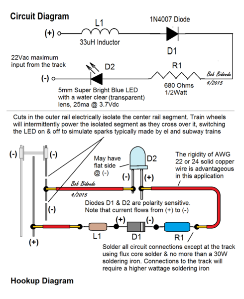
I did some research on the OGR Forum for posts about spark simulation, and what I found was inconclusive. So the reason for this post is to document a spark simulation circuit that I built and tested on the El of my layout. If you downloaded the prior sketch I posted before today (4/18/2015), discard it and download the updated sketch below.


Circuit - Spark Simulator

A Stan mentions in the post below, there are alternatives for Diode D1. I used a 1N4007 because that is what I have on hand, and of all of the 1N400X series diodes, the 1N4007 is the most rugged in terms of reverse voltage.


I iterated the size of the D2 LED and the value of the R1 Resistor. The 5mm Super Bright Blue LED with a water clear lens makes more dramatic spark simulations than a similar 3mm LED, and the water clear lens makes the LED difficult to spot when it is not illuminated. 680 Ohms for R1 gives a realistic spark simulation with the room lights on, yet it keeps the current flow through the LED below its maximum specification value for long life.


Build a test circuit before going into production, and optimize its geometric shape to fit the space you have available. In my application on the Flushing IRT El on Long Island, I spaced spark simulators about 3 feet apart, hence my reason for a single LED circuit rather than a string of LEDs. The simulators are impressive to see in action. 


There is a post below with a sketch of the installation technique I use on my layout. Finally, the sketch in this post is its last iteration.


Attachments

Images (1)
  • Circuit - Spark Simulator
Last edited by Bobby Ogage
Original Post

Replies sorted oldest to newest

For those interested, I'm guessing "Part 1" of the topic might be this thread:


https://ogrforum.ogaugerr.com/t...rk-simulation?page=1


As for comments to your diagram:

1. I think you mean 1N4007 Diode (not 1N1007).  However, you don't need the 1000V version of this diode.  1N4003 (200V) or 1N4004 (400V) have sufficient reverse voltage capability for O-gauge applications.  All the 1N400x diodes are the same price and size but if you got a good deal on the 1N4007 or have them already then you're good to go.

2. I suggest you add the graphic showing the polarity of the 3mm LED with the flat-side being the (-).  This would be like how you showed polarity on the diode with the band on the (-) side.

3. Are you sure about the 4.6Vdc @ 20mA spec for the Blue LED?  That seems a bit high; I'd think something closer to 3.5Vdc...but if you found a Blue LED with these specs that works well with your circuit, I suggest you give a part number or source.

4. By using a diode to rectify or convert the AC track voltage to pulsed DC, it can be confusing to analyze how much current is flowing through the LED.  If you have a voltmeter, simply measure the DC voltage across the R1 1000 ohm resistor.  That is, current = voltage / resistance.  So with the isolated rail powered via the axle, if you measure 10V DC across the 1000 ohm resistor, then the average current flowing into the LED is 10V / 1000 ohms = 0.01 Amps or 10 mA.  I'm surprised you get 20 mA average LED current (I'd expect lower) into the LED with R1=1000 and a single diode for AC-to-DC conversion, but so be it.


Thanks for your comments Stan. I will check the D1 Diode selection as you suggest. For the resistor value I used

R=(Vin - Vout)/ 20mA = 17.4/0.020=870 Ohms which I rounded up to 1000 Ohms.

The spec for the LED I have is 4.6V @ 30mA max, but I think less current through the LED will resolve the short LED life experienced in Part 1.

Stan2004,

I significantly revised the 1st post above taking heed of your suggestions. Thanks again for your help.

----------------------------------------------------------------------------------------------

The sketch in this post is the installation technique I use to install spark simulators on the Flushing IRT El on my layout. I spaced the simulators about 3 feet apart where they can be enjoyed by onlookers. The visual effect of the park simulators is dramatic eye candy, and using track power to illuminate the simulators has no apparent effect on the MTH DCS and PS2 trains operating on my El.


My El has MTH Real Trax, so hiding the circuit below the roadbed is easily done. However, for those using track with open ties, it will take a little effort to disguise the spark simulator circuit components. If I had to disguise the circuit, I would use track-side equipment boxes.


Installation - Spark Simulator

In closing, the spark simulation circuit is simple and very inexpensive to build. The spark effects are very dramatic and realistic. This is a great beginner electronics project. Try it! You will be impressed.

Attachments

Images (1)
  • Installation - Spark Simulator
Last edited by Bobby Ogage

Add Reply

Post

OGR Publishing, Inc., 1310 Eastside Centre Ct, Suite 6, Mountain Home, AR 72653
800-980-OGRR (6477)
www.ogaugerr.com

×
×
×
×
Link copied to your clipboard.
×
×