As my sign in says I'm pretty new at this and actually have a lot of questions. Let's start with an easy one. Can somebody tell me why the insulating pins on an O22 and an O27 are on different rails? Can they be mixed in a layout?
Replies sorted oldest to newest
You can mix them, but remember that O27 and standard O track is actually a different height, and the pins are a different diameter.
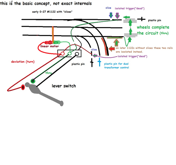
They are built differently that's all. The insulating pins are put on the section of rail that normally is "dead". The wheels complete the circuit by forming a connection to the "dead rail". this connection leads to the turnout coil. The turnouts switch coils other end, connects to the center rail.
Early 0-27 turnouts used a small slice in the outer rail. It was soon changed to the inside rails eliminating the slice seen on the early ones.(warning large trains and long cars cannot all run on 0-27. In a curve, the overhang hits the linear motor housing on the turnout.
(some other people/forums only use the correct term, turnout. Ask me how I know![]() )
)
O gauge is taller, and was made from heavier, thicker, metal (new?)
If you mix them plan to smooth the height transitions. Use adaptor pins unless you're willing to "tin knock" them into the correct shape.
My Marx bottom out on some Lionel 0-27 turnouts. On a plain loop they are fine. Marx and Lionel have bigger incompatibility issues in turnouts, drivers gear hit, and flange bumping.
Adriatic - I'm a bit confused. If the rail is "dead" how does it complete the circuit to the center rail? Does it signal the turnout on the other side of the loop to close/open? Next should additional section downstream of the turn out "dead" rail be isolated by removing the outer rail cross connect on the underneath of the fast track? I'm actually wanting to control the inner loop with a separate transformer.
trackrookie,
My advise is to set the power up on your 2 different track layouts in exactly the same manner, no confusion in this manner, with your 2 different transformers, each controlling it's own track layout. If you plan to use DCS remember the Red channel wire, goes to the mid rail, the black to an outside rail, and if you run Legacy connect it to the opposite outside rail. The 027 and 0 Gauge switches do not run on the same principle, the insulated pin depending on set up, will change in both.
PCRR/Dave
There's not requirement to connect the Legacy to a different outside rail than the DCS, you can connect them to the same rail. Many times, both outside rails are connected anyway, especially with Fastrack.
Trackrookie, two transformers must be phased to be used together. Watch this its easy..
Which switch numbers do you have?
The "dead rail" is only maybe 3/4" long
Later 1122s get the plastic pins on the inside(brown outline arrows)
All the old automatic switching anti-derails use a similar concept.
Homemade isolated trigger rails can be made various ways. From insulating whole rails with cardboard, to sticking metal tabs on with two sided tape. Isolated rails can be used to control blocks of track, or accessories too.
Attachments
You could also move the blue pin to the straight away center rail(thru) to change which throttle is in control of the turnouts track power.
First thank you. I think I need to go back to the basics here. What does DCS stand for (direct current source)? I thought the middle rail was the positive rail and the two outside rails negative, right? I have the 1122 without slices and yes they have insulating pins as you have shown. So do I need to put isolating pins in the black positions also? I intend to power the switches with an independent 14v source (I watched the Lionel video on this subject). I'm using a MRC Dual Power O27 transformer. I have assumed all of the negatives were internally connected and so I wouldn't need to phase the two power sides. Need I connect the negatives to achieve phased state? Finally (at least for now) I have managed to run an engine but when it enters the short side of the thru it dies. A small push and it takes off again? Also I have watched the Lionel video on creating an insulted rail and extending the block by removing the outside rail connector.
trackrookie:
DCS is MTH's version of command control.
TMCC / Legacy is Lionel's versions of command control.
You would need to purchase handhelds, command bases, etc to set this stuff up.
If you run off of the transformer only, then you are using conventional control.
You are correct - In 3 rail operation the middle rail is always power and the outside rails ground.
If you are using one transformer with two handles then yes the ground is common to both handles. There is no need to connect the grounds.
In general if you want to trigger an accessory (lights, gates, etc) isolate an outside rail and connect to accessory ground or use an IR detector (Lionel / MTH / Z-Stuff etc). If you want to create a power block (turn on/off locomotive independent of main line) isolate the middle rail and connect it to a toggle switch.
Joe
Never assume two transformers will be in phase. One sloppy job at the factory and your screwed. Check it. It is easy. Watch the video, its Lionel produced, but it applies to them all. Most new transformers will be in phase but it should be checked. Lionel wouldn't waste the time, or effort for a video about it, if it wasn't the right thing to do.
There is no true positive, or negative, with AC power. Each leg swaps this 60 times a second (120v, 60hz) One look at an AC sine wave on a graph should give you a visual why.(video again) Its better to say hot, and neutral/common, but we all screw that up quite often. So think it out, and ask if in doubt,
The early/late turnouts only need 2 plastic pins for the anti-derail. Either on the slit outside rails for the early ones, or the two inner on the late, not all four. Easy to check, introduce power at the entrance end(single end). Now use something(wire, wheels, etc) to touch the outer rail to the inner(not center). This switch rail should move(or "buzz" if already turned in that direction). All you are doing is supplying the "ground"![]() (common) to the otherwise complete circuit. Now try the other inside rail on the exit end. Both work? Your in business. Having fun jumping? Try an outer rail to a post(the 2 furthest from the switch housing) or from the one closest to the housing to either of the other two. Click!
(common) to the otherwise complete circuit. Now try the other inside rail on the exit end. Both work? Your in business. Having fun jumping? Try an outer rail to a post(the 2 furthest from the switch housing) or from the one closest to the housing to either of the other two. Click!
Now a question for you. How does everyone but me know you're running DCS when your new, and haven't posted before? ![]()
DCS= digital command system
trackrookie,
Part of the problem here is that in an earlier post you talk about using a separate transformer for an inner loop, but in a later post you talk about using an MRC Dual Power O27 (a single transformer with two separate controllers). If you plan to use the separate controllers for inner and outer loops, no phasing should be required. However, if you plan on using a "separate" transformer for the inner loop as stated earlier, then be sure to follow the phasing directions provided by Adriatic above.
Chuck
The insulating pins are used to create an insulated outside rail. One type of switch has this on the inside rail the other the outside rail. If you look closely at the outside rails either the inside rail or outside is cut. The plastic track pins go on this rail.
What you are doing is creating an insulated track that controls the non-derailing device on your switches. The wheels of the train pass common across the track making the switch turn to the direction the train is traveling.
F&G RY - Now I see. On the O22 it's a small slice and on the O27 (1122) there looks to be an plastic piece in the slice. just missed it.
PRR1950 - My bad it is a MRC Dual Power
Adriatic - Printed your test instructions and will give it a try (18v doesn't bother me).
All - Thanks. I'm having fun.
If you lean on the track, 18v will "prick" you. If your arms are sweaty, it will feel like a sharp object, or metal sliver poke. Don't put your tongue on it to test either![]() .
.
I tend to associate MRC with DC volts, and digital controls, which may change the whole approach.
Use of positive and negative terminology though understandable, has one eyebrow raised, and the other diving too.
They do make some nice AC pieces though. One even looks ZW-ish.
Confirm its AC volts on the output.
Listing exact part numbers for things you have, can be very helpful in expediting correct answers due to variations. Some wont bother trying unless you do.![]()
Have you checked out the free SCARM track design program? Its handy, & fun.
(watch you are selecting the proper download at scarm & not a google placed ad)
Anyrail had a free "limited number of track piece" test version.
If you had a plan ready, "painting" wiring onto a second file copy can speed things up too. Like a blackboard with your track on it.
Adriatic - Followed your instructions and the switches function properly. However when a I run a loco one of the anti-derails works but the other doesn't. Hum?? I'm working to secure my test track better to see if I have an intermittent or connection issue. Wish I had understood the difference in O22 and O27 track earlier. I think I saw someone post there are special pins to compensate for the difference in height.
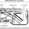
The tracks are different heights, and the rails are different diameters(the actual rail tubes - "O" pins are larger). Here is a comparison of pin placement for the 1122(E) and 022 switches:
Attachments
Like Rob says its a difference in diameter. That the adaptor pins fix that.
You still have to shim the 0-27 height to smooth it, or more sensitive stock will hop off at the angle produced at the tracks joint, a leaning apex.
Check the "DEAD" coil, and connections in its circuit, for continuity(do you have a multi-meter? (Volt/AMP/OHM). It is a valuable tool for model railroad electrical.
Even a cheap one will take care of most jobs.
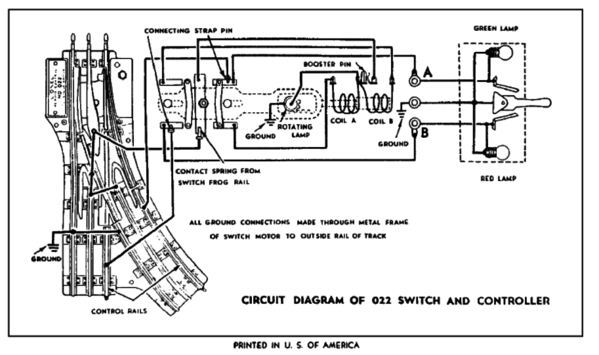
This one might be easier to read for the 022. Booster pin is a optional constant voltage power input. A nice feature I've hacked into some 1122s before. And the 022 motor can be mounted on either side of the switch.
This shows at least one ground better (on the lamp). I dont mind calling it ground here, it has the "earth" symbol.![]()
![]()

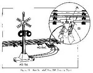
The 1045c contactor is based on the same trigger idea as the anti-derail. A fast way to ad a trigger. A mini, clamp on, isolated rail.
.
Attachments
You say it tests OK but not with a loco.
Do you have clean track?( scotch bright![]() , No sandpaper!
, No sandpaper!![]() No steel wool!
No steel wool!![]()
![]() )
)
Clean wheels? Don't trust your eyes, trust alcohol and Q-tips ![]() (alcohol on Q-tips)
(alcohol on Q-tips)![]()
Is a traction tire on the leading drivers?
Sometimes even with the plastic pins, the lower rail sections touch each other. That could cause a coil to remain energized, and burn it out. Doesn't happen a lot but can. It can also have a cancelling effect on the other direction. Moving the switch position by turning the signal lamp, while powered down, then again while powered up. With the latter, you would feel the linear motors resistance to your turning effort if a coil was "stuck on".
Adriatic - Hope you're still following. Sorry for the delay. Lots of balls in the air.
OK cleaned the track so the loco runs around the outer loop (inner loop is not connected), reset to insure good contact, and successfully tested the switches. Same problem. The 1122R (5122) operated the anti-derail but the 1122L (5121) does not. The loco is running counter clockwise (I know weird). So the loco enters the 1122R from the long side (bad terminology?) and the 1122L from the short (dead rail?) side.
No hurry. Be glad your not this guy.
Terms are understandable, that's what counts.
Though we rely on it language, understanding it is as variable, as big as the readers, writers, and words chosen that day.
Many responses are made for help posts. Much say the same thing in different ways.
And most tend to develop a clearer focus as the post progresses.
If/when I'm not clear let me know, Id like to be understood
(and being an insomniac, around day 3 my already crappie writing, suffers badly![]() )
)
I've heard the "proper" way is
"A turnout has one entrance, a "thru-exit", and "deviated exit".
"turn out" (proper, its not a switch, but has one).
Thru-traffic "into" the entrance. "into the straight exit" or "against it straight". With reverse travel noting: against, reverse, etc" .
- "entered the turnout" "entered against the turnout"" straight against the turnout" etc
(math is so much easier![]() )
)
So the NASCAR engine![]() traveling against any exit, should trip the A.D. circuit.
traveling against any exit, should trip the A.D. circuit.
(as you test, disconnect turnout track, and controls, till you need them, to assure against mixing any issues, before we can address the base functions)
Turn the switch lamp with your fingers, while powered down, to check for free movement.
Again while powered up, and you will feel resistance if there is an issue which could stop change in one, or both directions(ie: coils stuck "on").
Jumping a "live"(power on) outside rail to each control post should activate it.
Jumping a "live" outside rail to each trigger rail(2 per turnout) should activate it.
Use wire, (and finger pressure!) for tests, then wheels.
I think from what's written above by you, one trigger rail isn't making contact to its corresponding post, or a coil is fried/has an issue. Drilling out the rivets holding the bottom plate on may be required to check on the connections inside.
Do you have a multi-meter of any kind?(In the top 10 for "what tools are used most"
Harbor freight ones are ok. I think Gun Runner John had a good one linked in a post for under $20.
Another thing to look at for "coil stick" would be the little area just below the plastic pins. The flex and movement of track, can cause the lower rail sections to touch(and some aren't cut straight vertically) a small piece of card board and/or E-tape to guard those edges is necc. on occasion. Use a file to widen the gap down low, is the other option if they hit.
Adriatic - Well finally back again. Life throws curve balls. You are being of great assistance. I'm just still having terminology problems. Yes I do have a VOM and use it all the time.
So from your last post are you saying " ... a live outside rail..." do you mean I should to connect the positive to the outside rail and the jumper it to each outside post? If so where's the common? Or do you mean for me connect positive to the entrance center rail and the jump from the outside rail to each outside post? Sorry but I really need the specifics.
I will check for a stuck coil but I don't think that's the problem because I can make the switch activate in both direction by using the technique you gave me in post of 6 Feb at 12:13 pm. It may very well be a problem with a connection to a post. Here's' why. I tested (isolated) both the 1122R and 1122L as you described and they worked. Then I put them I the layout. The 1122R AD operated as the loco entered the "thru exit" however the AD did not operate when the loco entered the switch "entrance" of thee 1122L. Hope the crude drawing helps.
Attachments
Here's an update. With switch isolated, connected positive to entrance center rail. Tested by touching common wire to control (dead?)rails and the switch worked. Tested switch by touching common to posts and it switched back and forth just fine. Kind of confusing. Does it make any difference if the loco enters the "thru entrance" side of the switch versus the loco entering the "thru exit" side of the switch?
If it enters the single side of the Y, the non-derailing feature obviously doesn't change the switch position, or you'd never be able to take one of the routes! I'm not sure what you are asking here.
It does sound like it is working. Now the car test. Make sure it has metal wheels (some don't. Few, but some)
Track at 12-14v, face the turnout to turn. Now run a car against the straight exit. The first thing the wheels touch is the trigger rail, and the AD should move the swing rails to point at the straight. Now move the test stock to run against the curved side exit, as soon as it touches the trigger it should "save" you again. If this isn't happening clean your wheels, & clean the trigger rails better.
If your loco runs well at 8v, those switches aren't going to be happy at 8v. They need more voltage to work well. My old PW takes 12v easy. But some of my "can motors, are flying at 9v. There are electronic ways to slow a loco down to increase voltage on the track. Or just run long enough trains to let you keep it at 12-14v![]() . Or modify the turnout, to accept a dedicated voltage supply like I did.
. Or modify the turnout, to accept a dedicated voltage supply like I did.
It won't "do visible work" when traveling through the entrance into either exit. When it gets to either trip rail as it exits, the coil will try to move the turnout, but it will already be facing that particular exit, so it will just buzz, and push the swing rails, but cant move them further because they are in the correct position already.
And here is the base function of the auto derail safety system...
Without it, if traveling at an exit, if the swing tracks points are not facing correctly because we aren't being careful, the train derails/crashes.
But when our two front wheels connect the AD trigger rail to ground/black/common or other outside rails, the machine then swings the rail into the correct position before the crash can occur. I threw the bulb in. Internally, there is second lever of course.(you are using a dual handle, single housing controller right?)(test with cars, but without controllers first!)


