Here's another project that I'm toying with.  It's a replacement for the Lionel TMCC/Legacy 9V battery with a charger.  Since the TMCC/Legacy doesn't have charge capability, normally you use an Alkaline battery and have to swap them with some regularity.  This is a replacement that never needs to be change.  Since the battery module would get bulky with the charger combined, I'm thinking of two pieces, one is the two flat 5V super-caps and Zener charge balancing diodes, and the other is the charger module that connects to track power.  The battery module would have the two batteries sticking out to the side, and be encased in heat-shrink, and the charging circuit will be wired to the battery module.

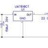
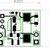
Since the battery negative goes to frame ground in TMCC, the charging circuit has to be a half-wave affair with frame ground as DC ground as well.  The TO220 regulator is on the back side of the board so it can be folded over to minimize the total size of the charging module.

Battery Module

Powered BCR Clone Battery Module Schematic

Charging Circuit

Powered BCR Clone Charger Schematic

Battery Module PCB

Powered BCR Clone Battery Module PCB

Charging Circuit PCB

Powered BCR Clone Charger PCB


Attachments

Images (4)
  • Powered BCR Clone Battery Module Schematic
  • Powered BCR Clone Charger Schematic
  • Powered BCR Clone Battery Module PCB
  • Powered BCR Clone Charger PCB
Last edited by gunrunnerjohn
Original Post

Replies sorted oldest to newest

PLCProf posted:

Do you really need 1.25 F? Reason I ask, there are some smaller supercaps, like the Eaton PB-5R0V105-R, that are rectangular and a pair of them would probably fit in a 9 V battery outline with room to spare (for the electronics.) But, a pair of them would give only .5 F.

That's a good question, I don't know at this point how much would be required.  The ones I specified are not all that much larger than those Eaton ones.  If I were going for size, maybe maybe I should just consider these on eBay, they're 5.5V 1.0F and would much more easily fit into the 9V form-factor.  They're $1.50 each and shipping for as many as you buy would be $2 total.  I actually have a bunch of this type of 1F capacitor in my parts box.

eBay: 162139053842

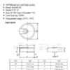
 5.5V 1F KAMCAP H Type Coin Electric Double Layer Farad Super Capacitor

Attachments

Images (1)
  • blobid0
Last edited by gunrunnerjohn
gunrunnerjohn posted:

Chuck, why would I make a 3V replacement, I'm targeting the TMCC/Legacy 9V battery replacement.  The only 3V requirement for a BCR clone is PS/2, which already has charging capability.

I don't know why, just got interested in researching what a BCR-3 might be

We see dropouts of some locomotives in command mode, both TMCC and Legacy in certain conditions, so I see a need for a battery in command or conventional mode.  If I use a battery, I want one that I never have to change and doesn't leak.

Obviously, if you perceive you have no issue, this topic probably isn't of interest to you.

I'm going to try the two 1F caps in series and see how long they'll hold up the RailSounds board, they may be all that's required.

Do you know the resistance of that cap?  Most coin-style supercaps have resistances measured in the 10's of ohms.  For example, eBay (182260239593) with similar pricing shows 15 ohms:

Untitled

So two stacked caps would be 30 ohms.  So let's say you need 1 Watt of power to drive the audio during track power interruptions.  The 9V battery would need to deliver over 100 mA so that would be a drop of 3V thru the caps' internal resistance and you'd only have 6V available to the electronics.  Additionally, a 1/2 Farad cap discharging 100 mA drops 0.2V per sec; I don't know how long the TMCC sounds run but this would be another consideration.

The Eaton supercap mentioned earlier has an internal resistance of less than 1 ohm due to different technology.  This is the type used in the BCR devices and in the MTH PS3 engines.  The coin-style caps are typically used in low discharge current applications and of course are much less expensive.   

Attachments

Images (1)
  • Untitled

I did note that Stan,I figured I'd try them and see what happens.  I have a few so I can give them a test and see how they do on a RailSounds board.  If they don't work, well, I haven't invested anything. 

Well... you're right, I was hoping that wouldn't be too much internal resistance.  I guess I'll keep looking...

I'd like to find a lower cost alternative to the $5 capacitors, that bumps the price up quite a bit.  I'd like to be able to get all the parts for something like this for $10 or less, including the circuit board.  I'd also like it to be as small as possible.

I have a couple thoughts, but not sure about any of them.  

The first is to perhaps use 3 of the inexpensive Caps, to allow maybe a 12-15v charge level.  This would require input and output regulators, so adds a step of complexity, but it may be less expensive that way.  

Second idea is to use just 1 good quality super cap, and a boost module to raise it's 5v to 9v.  Here, I'm unsure if a booster would provide enough current. 

The last is more of a question, while a 9v battery is used for the sound system, is the railsounds board actually running at 5v?  if so, would it be possible to add the supercap to the board in a way that bypasses the step down from 9v to 5v?  It would make for a more complex install, obviously, but may make for much fewer parts as you pretty much only need to limit in-rush current to the cap.  

JGL

John, I looked at both of those options, but I think just using two of the proven 5V supercaps is the way to go.  Trying to add multiple regulators seems like way more complicated than this project should be, and boosting it requires either using one of the cheap eBay switcher modules, or laying out a boost regulator.  Neither of these are attractive options, at least to me.

No way I want to screw around tapping into the RailSounds board, that is messy beyond belief!  Besides, this will be a project that the great unwashed masses might want to use, and there are very few people that would be able to hack into the boards to attach this, and even fewer that would want to.

gunrunnerjohn posted:
sinclair posted:

Now, the next question is, you have looked into adding this to a locomotive that doesn't have a battery, like the VLBB and the B6sb?

No way to do that for those that don't have a battery.  If the circuit on the sound board isn't there, that's all she wrote.

Do we know the circuit isn't on the board, or is it there, but unpopulated, or is it there and populated but just doesn't have a battery connector?  I was under the impression the boards were mostly modular, they just changed the sound chips.  If they spun custom boards for these locomotives, then I understand that's all there is to it.

I have a couple of Legacy diesels that I would be interested in adding your super cap 'batteries' to. Haven't had a problem with them, but you never know. However, after reading about the VLBB above, I better look to see if they can even accept a battery. I think the project does seem like a good idea, I have seen a few posts with folks wanting to have a battery of some sort in their TMCC engines. 

Also, probably a dumb question, but why would they leave the battery connection out of the VLBB, or any other engine for that matter? Is the VLBB long enough, having more pick-up rollers so it's not needed? And would space could be a problem in the smaller engines? Just curious on your thoughts about this.

Well, the 9V (8.4V) BCR retails for $24.95.  I realize it's not exactly apples-to-apples since, as I understand it, for TMCC it is a nice-to-have sound option whereas for MTH PS2 it is required.  So if this is something you're planning to make available to others it seems you have a kind-of-sort-of benchmark which, to me anyway, suggests you have a reasonable amount of wiggle room wrt squeezing out the last penny from the design.

In your testing, have you noted actual power/voltage/current requirements?  I'd think the 9V battery is powering a step-down regulator to, say, 5V?  And if so does this mean it works with 8V, 7V, 6V, ?V at the terminals?  And what is the current and for how long?

From what I've seen, the cost of the low-resistance supercaps has not fallen dramatically especially compared to semiconductor regulator components/modules.  If you're trying to develop a "kit" for others to mess with, learn from, etc., that's one thing.  But if you're trying to engineer a product I'd think a dual regulator configuration stepping-down to the storage voltage...then stepping-up to 9V (or whatever is needed) is worth a look.  The MTH PS2-3V with ~2.5V batteries is a dual regulator configuration.

The $25 BCR doesn't have a charger, so that's not exactly an apples to apples comparison.

I check the power requirements for a standard RS4 board when just running normal sounds, I cut the track power and measured what the board drew from the battery.  It was around 82ma and dropped a bit as the volume went down at the last of the shutdown sounds.  With two series 2.5F caps, I could run the shutdown four times before the board doesn't get enough voltage to run, that was about six and a half volts on the caps. 

If I could find the 1F or 1.5F caps significantly cheaper, it would probably make this a better deal, but I didn't find anything close.  There is one eBay vendor, but he couldn't tell me the internal resistance of his product, so I was reluctant to order those.  It appears that .5F would be plenty for the purpose, it only has to hold the sound for a second or two in real life.  I'm pretty sure fully charged the .5F could manage one shutdown sequence.  I was really looking for something smaller, but the 1F caps seem to be almost as large as the 2.5F ones I'm using.

My idea of this is a kit or perhaps just the board, I don't see any way I'd tool up to make 100+ of these, too big an investment for an uncertain return.  However, I'm sure some folks would like to equip their fleet with some of these.

I realized that it was somewhat of a kludge with two boards, so I tried it with one board. three boards are $4.90.  The supercaps go on the back laid on their side, and all the other components go on the front.  the regulator, being the tall component, folds down on the board.  I would think you'd simple heatshrink the whole affair after attaching the track power wires and the battery clip.  with the caps sticking out the end, it's a bit less than 2" long, .8" wide, and 5/8" thick.


Attachments

Images (2)
  • blobid0
  • blobid1

I have a NiMH, I think, (might be a NiCad) in the ZW-C add on volt/ammeter. It seems to work well, but I do worry about it from time to time. I'd feel safer with capacitors.

Actually years ago I made little circuit to show if one desk phone was off the hook of a couple phones on the same 2 wire line. I used a regular alkaline 9 v battery and trickle charged it with a 100K or so with the phone line voltage always present...forget what that was. Anyway it lasted many years that way.

Last edited by cjack
cjack posted:

I have a NiMH, I think, (might be a NiCad) in the ZW-C add on volt/ammeter. It seems to work well, but I do worry about it from time to time. I'd feel safer with capacitors.

Actually years ago I made little circuit to show if one desk phone was off the hook of a couple phones on the same 2 wire line. I used a regular alkaline 9 v battery and trickle charged it with a 100K or so with the phone line voltage always present...forget what that was. Anyway it lasted many years that way.

In 1972 I received as a gift an electronic flash unit(!) that ran on the uncommon rechargeable alkaline batteries.

44 years later, the flash doesn't work, but the batteries and charger do! Must be some kind of record. I put them in my "museum" drawer along with the 100 kilocycle crystal and recording wire.

Using your current measurement of 82mA from a 9V battery for 2 seconds, that's 1.5 Joules of energy.  A 5V, 1/2 Farad supercap stores just over 6 Joules of energy.  So if you used a dual-regulator design, perhaps even piggy-backing with a 75 cent (free shipping) eBay step-up module, I think you might be able to cram it and the charger into a 9V battery outline.

IMG_1416

There are only 7 components on the boost converter module which claims over 1 Amp output capability.  And of course you wouldn't need the rather bulky voltage adjust trimpot since you'd set the boosted output voltage to a fixed 6.5V (or whatever minimum you need).   And if you only need, say, 100mA of output current you can probably get by with a smaller inductor which is the 2nd largest component on the module.

A nice feature of the boost module is it operates down to about 2V input.  Note that if you use two stacked 5V supercaps, you are leaving a good chunk of energy on the table.  That is, it appears you're clamping the supercaps at 9.4V.  So you only get energy as the caps discharge from 9.4V down to 6.5V.  So you only use about 50% of the available energy.  OTOH, if you have a 5V supercap and you can draw it down to 2V, you use about 75% of the available energy.  Of course there are efficiency losses in stepping up voltage but I think the numbers are worth crunching.


Attachments

Images (1)
  • IMG_1416

Well, we also need the charging circuit for the 5V supercap.  I'm somewhat loath to start sticking eBay modules into the mix, they tend to come and go.  It would be nice to come up with a switching regulator design that didn't take up too much space, I should look into that.  I presume the charging circuit could be limited to around 100ma or less and still do the job.

I recall the discussion on boosting a single supercap as opposed to using two we had previously.

Last edited by gunrunnerjohn

Well, that 3 Watt charging resistor did initially strike me as an elephant in the corner.  Again, it depends if this is to brute-force a simple solution that gets the job done...or to engineer it for philosophical or to polish the walls on the ivory tower.   For example, constant-current charging is as "simple" as a LM317 plus a resistor.  A voltage cut-off circuit to stop rapid charging and revert to trickle-charging is also not rocket-science.  I think another design question is how fast the battery has to be ready to hit the ground running...and with what kind of duty cycle.  For example, taking the MTH battery as an extreme case, it has huge capacity and can handle many power interruptions one after the other...but takes quite a bit of time to initially charge to even operate one interruption.  I'd think you have similar trade-offs with this design especially if limited to a modest charging currents like 100 mA which of course is on par with the discharge current.

Last edited by stan2004

The 3W resistor was a hammer, but it worked.   Didn't you see, I dropped it a 2W resistor later.

I did think of constant current, but then I thought about voltage cutoff and decided to take the easy way out.   If we had a simple voltage cutoff, I don't know as we need trickle charging, when the voltage falls, it would start charging again.

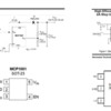
I found this Microchip part for less than $1 in quantity one, and it allows up to 5.5V in and a variable voltage out.  Seven parts, not too bad, and I could program it for 7.5 to 8.0 volts out, that should insure positive result.  It'll do up to 200ma at 7-8 volts, should be sufficient, and it's a small footprint part.

Attachments

Images (1)
  • blobid0

So are you saying you're willing to consider the dual-regulator step-down/step-up approach using a single 5V supercap (low-resistance type)?  More components for sure but unless those supercaps come way down in price it sure seems the dual-regulator approach has an undeniable cost advantage whether it be 7 more components or even double that.   I couldn't find an easy-to-find source for the MT3608 AeroSemi boost converter, but I guess it comes as no surprise that its topology is identical to the MCP1661 Microchip converter.  In fact, it seems you could layout with a SOT-23-6 footprint to handle both chips!

mcp1661 mt3608

I've given up pondering how you can get quantity 1 assembled (and presumably tested) eBay module with all 7 components shipped to the U.S. for less than the price of just the MCP1661 from DigiKey!

Anyway, as I see it, the charging method depends on the requirements for how fast, how often, this battery replacement needs to be called into service.  I have no problems with the simple 2W resistor current limiter if it does the job...


Attachments

Images (1)
  • mcp1661 mt3608

Ive noticed Johns solutions are direct and pointed to the problem at hand with an emphasis on simple. I'd say its worth a little more on the front side to stay withing the confines of simple. The best solutions are the ones that are the shortest rout to the answer. John, when you get the design hammered out and if you decide to sell a bunch of kits Id easily take more than 10 maybe 20. I cant stand when my command locos drop sound its alwasy a pita to get the sound back up

stan2004 posted:

So are you saying you're willing to consider the dual-regulator step-down/step-up approach using a single 5V supercap (low-resistance type)?  

Sure, if I was not going to consider suggestions from the bench, I'd just build one.

stan2004 posted:

More components for sure but unless those supercaps come way down in price it sure seems the dual-regulator approach has an undeniable cost advantage whether it be 7 more components or even double that.   I couldn't find an easy-to-find source for the MT3608 AeroSemi boost converter, but I guess it comes as no surprise that its topology is identical to the MCP1661 Microchip converter.  In fact, it seems you could layout with a SOT-23-6 footprint to handle both chips!

I normally stick with chips I can get from a reliable source, simply because if I design something and then later decide on making quantities, I want to be able to get the parts.  I did look around for the MT3608, but as you say, they seem to be hard to buy.

stan2004 posted:

I've given up pondering how you can get quantity 1 assembled (and presumably tested) eBay module with all 7 components shipped to the U.S. for less than the price of just the MCP1661 from DigiKey!

Anyway, as I see it, the charging method depends on the requirements for how fast, how often, this battery replacement needs to be called into service.  I have no problems with the simple 2W resistor current limiter if it does the job...


I marvel at the Chinese prices, clearly they have some government help in maintaining those prices. Of course, the USPS subsidizes their shipping like the idiots we are, I'd love to understand why that policy exists! The resistor does the trick, but I'm open to a more elegant solution, especially if it costs significantly less. Let's talk about the constant current and limiting the charge to 5V maximum. How were you visualizing accomplishing that? Is there a simple trick to add to the LM317 circuit to cutoff at a specific voltage? I was thinking along the lines of a Zener diode circuit.

John, the postal service covers the inbound shipping because of a century old international agreement or treaty. When it was enacted this wasn't at all a concern and i'm sure it benefited us. It was done to help ensure reliable and consistent postal delivery around the world which it did.

Add Reply

Post

OGR Publishing, Inc., 1310 Eastside Centre Ct, Suite 6, Mountain Home, AR 72653
800-980-OGRR (6477)
www.ogaugerr.com

×
×
×
×
Link copied to your clipboard.
×
×