


JGL, the RailSounds boards used by ERR and in later Lionel products is the target market, they have no internal power connector. The LC product line wasn't even in the picture as it's never had a backup battery capability for the sound.
PLCProf posted:gunrunnerjohn posted:It's the bridge rectifier that supplies power that causes the problem. The DC ground is not frame ground on all the new Lionel/ERR Sound board products. I presume the battery is connected to DC ground internally, but it really won't matter if we figure out an isolated supply scheme.
Well, if we knew for sure how the new Lionel/ERR stuff was wired, you might be able to do something like the attached. Note that the added rectifier parallels one of the rectifiers in the bridge.
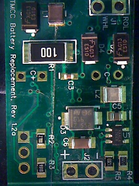
Hmm... Interesting, but I don't know that most folks want to hack into their RailSounds boards to accomplish this. I do know where the bridge rectifier is in the input, I received a couple for repair that had their chuff sensors connected to frame ground, they promptly blew the bridge. The arrow below points to the bridge rectifier.

Attachments
Images (1)

I understand there is no application for LC. It was just an example of grabbing power from some connector on board. In the case of the board shown above, what does the volume control pot plug look like on each pin? I'd give it a 50/50 shot of having +5 on one pin and ground on another. May not provide much current, but that would take a moment to trace back.
JGL
Edit: Actually looking at this image of a similar board it looks like ground and 3.3v

this is from the (6981186T01) Frisco LEGACY Scale Heavy Mikado 2-8-2 Tender Only #4126 which was the first steam engine I found searching for 'legacy' in the parts dept.
We need a hundred or probably a lot more milliamps to charge the supercap in any reasonable time. There's nothing on that board that would allow us to draw that kind of power! In any case, I'd like to make this a PnP project. Hacking the board is really not in my game plan. If someone else wants to take the "hack the board" path, that's fine. I just don't see that as a very interesting way to go, and it certainly won't have universal appeal.
I'm pretty stuck on isolating the battery module so that it's universally compatible.
gunrunnerjohn posted:PLCProf posted:gunrunnerjohn posted:It's the bridge rectifier that supplies power that causes the problem. The DC ground is not frame ground on all the new Lionel/ERR Sound board products. I presume the battery is connected to DC ground internally, but it really won't matter if we figure out an isolated supply scheme.
Well, if we knew for sure how the new Lionel/ERR stuff was wired, you might be able to do something like the attached. Note that the added rectifier parallels one of the rectifiers in the bridge.
Hmm... Interesting, but I don't know that most folks want to hack into their RailSounds boards to accomplish this. I do know where the bridge rectifier is in the input, I received a couple for repair that had their chuff sensors connected to frame ground, they promptly blew the bridge. The arrow below points to the bridge rectifier.
If we knew for sure that the battery was directly connected to one side of the bridge rectifier no hacking would be involved! Just connections to the roller, ground and battery.
You're right, I'll check that! I wasn't thinking outside the box. ![]() That would be almost too easy.
That would be almost too easy.
DING...DING...DING... we have a winner!
Looks like a direct connection from the DC common to the battery. Hard to believe it'll be that easy to fix! ![]() I obviously already have connections to all those points on my board.
I obviously already have connections to all those points on my board.
gunrunnerjohn posted:DING...DING...DING... we have a winner!
Looks like a direct connection from the DC common to the battery. Hard to believe it'll be that easy to fix!
I obviously already have connections to all those points on my board.
Well, try it before you give out any gold stars.
Never underestimate the perversity of the inanimate........
Before I risk an $80 RailSounds board, I think I'll mock this up on the bench to see if I get any adverse reactions. Given that it appears to parallel the internal diode, it sure seems that it wouldn't affect anything. We do lose around .6 volts or so from the "battery" ouput in the diode, so I may have to boost the output voltage a bit, that's just a resistor change in the switcher circuit.
Looks like a Rev. 3 may be coming up soon. ![]()
--- EDIT ---
You read my mind, I was thinking of checking this out before actually doing it. I can just wire the diode externally for a test. I could also provide a jumper to short it for old RailSounds to give additional power.
Nothing blew up in a simple bench test, I'm working up my courage to try it on my audio board. ![]()

If the "added" diode is simply parallel'ing the internal diode (in the bridge), is it needed? That is, you have to design for the case where the diode characteristics are slightly off between the "added" diode and the mirror diode such that one or the other takes the combined current. So if the 9V battery minus ties to the Lionel ground in both cases, wouldn't this allow a simpler 1-wire connection to just the Center roller (after plugging in the battery)?

Attachments
Images (1)
Well, the little bridge on the RailSounds board may strain under the load of my charging circuit, it draws half an amp at startup. I wouldn't want that little bridge to have to handle that current, I suspect it might complain. The last thing I want this to do is to cook someone's Legacy RailSounds board, so I'm going to err on the side of caution.
Truth be told, I was thinking of a Schottky diode to insure it carried the load, but I didn't know if that would create other issues having the bridge unbalanced. I think I'll just try with the parallel diode and see how that shakes out.
The Bridge on the RS Commander is a Diodes, Inc HD04, it has an .4A voltage drop of 1 volt per element (I presume that's for each diode). The Fairchild ES1D I use is a 1A diode with a voltage drop of .92 volts at 1 amp. I'd like to think my diode would be picking up much of the slack and not causing any issues with the RailSounds board as far as excessive current. I'm assuming the RailSounds board doesn't draw that much power, after all it runs on around 80-100ma from the battery. ![]()
If there are other factors I'm missing, I'm all ears. ![]()
Success!!!
I added the diode in the frame ground lead on my prototype and tried it with the ERR RailSounds Commander. Works like a champ, and also works with the RailSounds board of similar construction in Legacy. The compatibility of the battery replacement just went up a bunch. I'm a lot happier with this now, it should work with most RailSounds environments.
Congratulations, sounds like another nice project you have successfully come up with!
I am staying tuned to see what will be next. ![]()
Well, I had some help with my friends with some key parts of the design, so I thank them for their contributions. Stan and PLCPROF have certainly played a key part in the road to success here. ![]()
I certainly think those are two very good friends to have too. You three get a lot worked out around here and I enjoy watching it all happen right before my eyes. Glad you all share with the rest of us. Just wish I know more so maybe I could add just a little something every now and then.
After my "final" testing... ( I love the word final ![]() ), I decided to go with the single wire to center roller power and let the ground be supplied by the RailSounds board. I didn't see any issues with excessive heating of the bridge for the short charging cycle drawing the ground return current through the single board RS that's used for ERR and Legacy, so I went for the simple connection. A bonus of the single wire is there's no possibility for someone reversing the wires and cooking something, if you plug the battery in and ground the single power wire, nothing happens. OTOH, if you were to connect the ground wire on the previous version to track power, very bad things would happen! That tipped the scale in favor of eliminating the separate ground wire.
), I decided to go with the single wire to center roller power and let the ground be supplied by the RailSounds board. I didn't see any issues with excessive heating of the bridge for the short charging cycle drawing the ground return current through the single board RS that's used for ERR and Legacy, so I went for the simple connection. A bonus of the single wire is there's no possibility for someone reversing the wires and cooking something, if you plug the battery in and ground the single power wire, nothing happens. OTOH, if you were to connect the ground wire on the previous version to track power, very bad things would happen! That tipped the scale in favor of eliminating the separate ground wire.
The production versions will have the single track power wire, though under the skin for the first run they retain that parallel diode if for some reason it's deemed desirable, just hedging my bets. ![]()
John,
When do you think you will have these available for sale?
Working on that now. Waiting on boards, presumably coming from China, and the assembly house will then build them. I'm guessing in the 2-3 week time frame at the soonest.
Moving along. Just got the "verification" shot from the board house, good thing as two resistors were swapped. All good now, and they should be running the boards in the next couple of days. I add the two thru-hole parts and the battery clip and put the heatshrink on them here. My "final" layout added an extra set of connections for the supercap for the wider spaced leads, those seemed to be a bit easier to find.
Attachments
Images (1)

Excellent! Can't wait to get the batteries out of my TMCC and Legacy engines. All this talk about batteries leaking worries me.
Can someone give me some guidelines as to what engines these work in? Any Lionel with a 9 volt? Or?
They should work in any Lionel with a 9V battery, TMCC or Legacy. The production has a very simple hookup, one wire to the center roller and replace the battery with the product. Most of the time, the center roller is connected in a wire nut, so you just add the TMCC Battery Replacement power to the connection.
Did you look in to what happens if someone plugs this into a MTH PS2-5V board instead of the rechargeable 9V battery? Is it benign or will bad things happen? Do you need one of those warning labels like for hair-dryers saying not to use when taking a bath? ![]()
Honestly Stan, I did not. I will probably specifically state in the instruction sheet where it's to be used. It appears that it should be benign, but I didn't actually test it. The diode should block the positive voltage from anything but the resistor divider, I suspect the 732K resistor will limit any possible damage to the switcher chip from the MTH charging voltage. Here's the output regulator side.

Attachments
Images (1)

I agree on the battery terminals but would anyone be fool-hardy enough to connect the charging wire to the center roller? ![]() Or am I just being paranoid!
Or am I just being paranoid!
I was thinking about some kind of label you insert under the presumably "clear" heatshrink wrap. Something like "NOT FOR USE IN MTH" or "ONLY FOR USE IN TMCC"...
Stan, that might be bad, especially since I'm depending on the characteristics of the TMCC and Legacy RS boards. However, you may be a bit paranoid, after all, if you do a lot of stuff to these products you can blow them up. ![]() In looking at the whole schematic, I don't think there's much danger, even connecting the power to the input lead. One of the reasons for losing the ground connection is that was a danger if you swapped the ground and center track connection, the Legacy boards would NOT like that. However, if you connect the single center track connection to ground, no harm, no foul, it just won't do anything. I think it's fairly benign with the single wire connection, even if you're dumb enough to put it into an MTH locomotive. I wouldn't take that to the bank, but at first blush it seems like mostly a non-issue.
In looking at the whole schematic, I don't think there's much danger, even connecting the power to the input lead. One of the reasons for losing the ground connection is that was a danger if you swapped the ground and center track connection, the Legacy boards would NOT like that. However, if you connect the single center track connection to ground, no harm, no foul, it just won't do anything. I think it's fairly benign with the single wire connection, even if you're dumb enough to put it into an MTH locomotive. I wouldn't take that to the bank, but at first blush it seems like mostly a non-issue.
I'm actually using black heatshrink for the production versions, just got a 100 feet of it, basically a lifetime supply! Of course, I use it for encasing the Super-Chuffer for installations as well, so maybe someday I'll run out. It was only a few bucks more than 25 feet of it, so I figured I'd go for it.
Did I mention another GRJ product was going to be pre-packaged 1" heatshrink tubing? ![]()
![]()
gunrunnerjohn posted:Working on that now. Waiting on boards, presumably coming from China, and the assembly house will then build them. I'm guessing in the 2-3 week time frame at the soonest.
Hi John,
Too bad 'other' manufacturers of of train stuff cannot seem to get a great turnaround time like you!!! ...AND you don't even require a deposit ![]()
THANKS for all of your terrific work!!!!!!!!!!!!!!!!!!!
Best, Dave
Still waiting on the shipment. ![]() I did get a proof picture of component placement, and it's a good thing. They had two resistors swapped, so we corrected that and presumably they ran the boards this week. Since they also have Chuff-Generators and lighting modules to run, they might be waiting to ship all of them in one shipment.
I did get a proof picture of component placement, and it's a good thing. They had two resistors swapped, so we corrected that and presumably they ran the boards this week. Since they also have Chuff-Generators and lighting modules to run, they might be waiting to ship all of them in one shipment.
Here's something that some will be surprised to see, a sample of the finished product! ![]()


We appear to have met the design goals. The battery easily fits in the space for the Alkaline battery, and it even has room to rattle around. There is some minor assembly required locally, I have to solder on the three non-SMT components, the wire, and of course put on the heatshrink.
Now I'm working on the packaging and the instructions. Of course, I also have to do the finish work on them as well. However, the two production samples I finished and tested work great, so it's in the can so to speak.
Attachments
Images (3)


Awesome job John!
"We appear to have met the design goals. The battery easily fits in the space for the Alkaline battery, and it even has room to rattle around. There is some minor assembly required locally, I have to solder on the three non-SMT components, the wire, and of course put on the heatshrink."
"Now I'm working on the packaging and the instructions. Of course, I also have to do the finish work on them as well. However, the two production samples I finished and tested work great, so it's in the can so to speak."
Do you have an idea of 'out the door' pricing and when they will be available?
![]()
Looks like another fine product from GRJ's Electronics Mfg, Inc. !! I suspect you may need to make a lot of these. ![]()
rtr12 posted:I suspect you may need to make a lot of these.
From your lips to God's ears. ![]()
Here's a first cut at the included documentation, anyone see something that's suggest adding? It's a bit hard to expand on this too much, it is only one wire! ![]() I also came up with a name.
I also came up with a name. ![]()

Attachments
Images (1)

$30? Does it come in solder your own kit form?
gunrunnerjohn posted:Here's a first cut at the included documentation, anyone see something that's suggest adding? It's a bit hard to expand on this too much, it is only one wire!
I also came up with a name.
Looks good to me and sounds easy enough to do. (I think Stan may like the name too? Thinking of the PBW.)
I think there is a typo next to the battery picture in the first line... "Installation is very simply". Seems that should be simple.
So is this on the Hennings trains website for purchase?
Has he priced them yet? Also I am not sure if he will be offering kit form or not?
Add Reply
Sign In To Reply
