Today, for the first time, I placed a recently acquired Atlas Maersk GP-60 on my layout.  Tested it out, once around the loop, everything fine.  Thinking that my MTH Premier Maersk GP-60  dummy would look cool behind it, I placed it right behind the Atlas.  As soon as I powered up the track (this is with an MRC Pure Power Dual transformer) the ammeter shot to the max (I think the voltage had barely ticked past 5) and the circuit tripped.  Tried resetting it, running the same way, got the same result.  I removed the MTH Maersk dummy, and the Atlas runs fine.  Could the lighting on the dummy be that intense that THAT would be the problem?  Or is there something more complicated involving Atlas vs. MTH electronics?  If I wanted to do this again, would I have to remove the bulbs in the MTH dummy and replace them with lower voltage bulbs, or maybe LEDs?


Just for the record, I have the Lionel Maersk SD-70, and I'm pretty sure I've run it with the MTH Maesrk dummy without a problem.


- Mike

Original Post

Replies sorted oldest to newest

Well, first the good news.  The problem, as you suspected, is in the dummy.  


Now the bad news.  After about an hour and a half of detaching and reattaching connectors, 


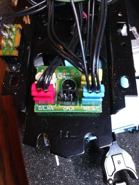
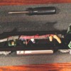
IMG_0958


wrapping electrical tape around what seemed to be the slightest frayed area, repositioning wires to fit better within the shell, nothing seems to help.


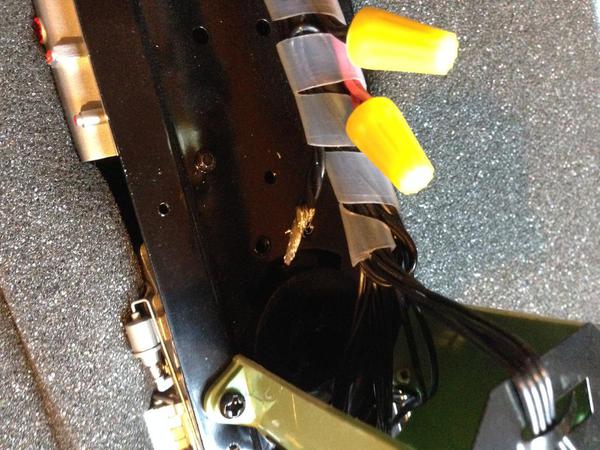
IMG_0959


So I'm at my end point.  I need and will seek out professional help!!  One thing I did notice when I placed this opened dummy on the track and gently throttled up.  I could hear a very faint sort of buzzing/crackling type noise coming from what appeared to be this area.  It was hard to determine because the noise was so faint and did not seem to get louder as I powered up (and the circuit would trip again anyway before I got too much further.


IMG_0964


Thanks guys for your helpfulness.  If and when I learn the root of the problem I will try to report back what the fix was.


- Mike

Attachments

Images (3)
  • IMG_0958
  • IMG_0959
  • IMG_0964
Last edited by mike.caruso
Originally Posted by AGHRMatt:

Turn off the dummy's lights and see what happens. If the short goes away, you have a bad lighting board. As a practical matter, making a replacement circuit or using batteries (simplest approach) is probably cheaper than buying replacements from MTH.

Do you mean by pulling all of these?  Actually, there currently are no lights when I place it on the track.  I think the very first moment I tried it with the Atlas engine, they both had lights for a second and then the circuit tripped and that was it.


IMG_0958

Attachments

Images (1)
  • IMG_0958
Last edited by mike.caruso

Do you own a volt-ohm meter? I would start tracing from the rollers inward to and through the various circuit boards.


Not being familiar with the loco in question, since you say it has lights, can you remove the lamps from the sockets and see if you have a shorted lamp?


Also, forgive my ignorance, but why all those wires for a "dummy"? Does it do things that require all that stuff? Sounds, etc?

Last edited by Arthur P. Bloom

Art, beats me.  This is what the MTH description mentions.


Features

  • (2) Operating Metal Couplers
  • Illuminated Number Boards
  • Constant Voltage Headlight

Plus, one odd thing.  There's a smoke switch on the underside ; I set it to "off."  I wonder whether this had been a powered unit originally that someone converted to a dummy .  The shell has the correct dummy # 151.  But there's the smoke switch and gears on the underside.

Last edited by mike.caruso

Does power come from two wheel- trucks via a pair of red and black wires that go into twist wire-nuts like on their powered-units?  If so, you can un-twist one wire nut and separate the wires.  This isolates the trucks.  Then with an open-end piece of track or whatever you can apply track power to one truck at a time to see if the short is in the truck.


I didn't catch if you said you had a multi-meter but you could also test each truck individually for a short that way too once you un-twist the wire-nut and separate the red or black track power wires.

20- 2871-3 was the box it came in.  But because of the cab number and the smoke unit switch, I'm guessing this was not the original shell.


I just placed it on the track with all the pickup rollers taped.  I then untaped just a single roller towards the rear of the engine and applied the power, ammeter soared to max.  I retyped everything and uncovered a single roller on the front-end pickups, same result.  Does that mean the problem is not with one particular set of pickups but rather is located somewhere "in between" for lack of a more technical term?

Hello Matt, and thanks.  I tried.  Didn't seem to help.  (Although I'm a little confused...doesn't the FET sort of sit perpendicularly on the metal when its screwed into place? ) I took the screw out so the board assembly was sort of "floating" a bit, not touching anything..and placed it on the track but got same result.

Originally Posted by GGG:

Which model?  Does the dummy have a 2R and 3R switch?  Otherwise sounds like a bad CV board.  That should be an easy fix.  No smoke unit on this model?  G

This doesn't seem to have any 2R/3R switch.  The only thing I can see is a smoke switch, yet this unit did not have smoke, nor is there any funnel or stack.

Originally Posted by stan2004:

, you need to separate that internal connection to separate the two power sources from the boards/electronics.  


Any particular instruction or chance you could explain  how to do that, based on what you see here?


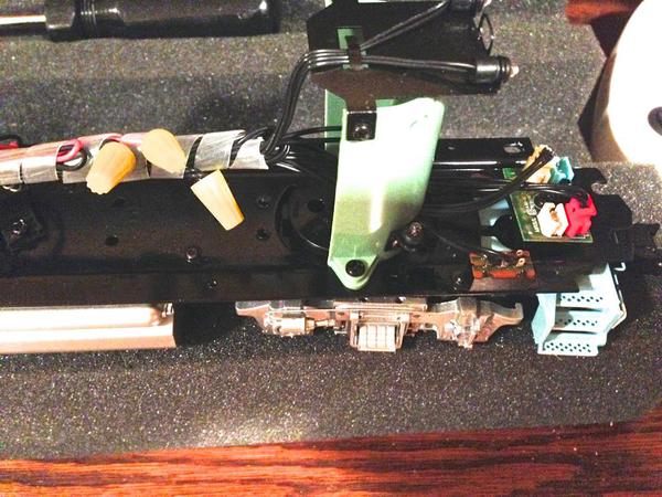
Overall view


chassis


Front end


chassis1


Back end


chassis2

Attachments

Images (3)
  • chassis
  • chassis1
  • chassis2

I believe you will find a red and black wire from each wheel truck supplying power to the electronics.  This is circled in yellow from your photo below.


truck screws can short


Can't quite see this on the right side of your dummy but it probably has the same hookup there.  In greatly magnified view as below I believe you'll see them screwed into the truck.  I have seen these connections loosen where the wires or lugs rotate or get nicked as the wheels trucks are moving relative to the chassis particularly when going around curves.  So carefully inspect these areas on the trucks for shorts between black and red or between red and the chassis.

red black to screws truck

As far as isolating the trucks, I am referring to those yellow wire-nuts.  I believe the red wire from each truck comes to the red wire nut, and the black wire from each truck comes to the black wire nut.  I don't know what that 3rd wire nut is but may not be relevant for now.  Anyway, you'll somehow have to determine (I realize this can be a challenge with the harness spiral wrap) which is the red nut and the black nut.  Then un-twist the nuts and separate the wires.  Now the two trucks will be isolated and the electronics will no longer receive track power.  I'm guessing that the red and black nuts each have a 3rd wire going to the board electronics.


Now put the engine on the track and see if you still have a short.


If I read the lettering on the "FET", it seems to be 7806A.  The 7806A is a voltage regulator (not a FET) that generates 6V which sounds right given MTH uses 6V bulbs.  Not that it matters what it's called since it doesn't seem to be the issue...

Attachments

Images (2)
  • truck screws can short
  • red black to screws truck

I would take take the red wire nut off and separate the wires form each other and see if you still have a short. If so then your issue lies most likely in one of the trucks. If no short then reconnect the red wires one at a time and test for the short every time you connect a wire

Add Reply

Post

OGR Publishing, Inc., 1310 Eastside Centre Ct, Suite 6, Mountain Home, AR 72653
800-980-OGRR (6477)
www.ogaugerr.com

×
×
×
×
Link copied to your clipboard.
×
×